- Title. Author. Summary

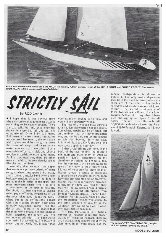
Rod Carr’s scratch-built TRACER is the MACH II design by Adrian Brewer, father of the SONIC BOOM, and SOUND EFFECT. The overall length (LOA) is 66.5 inches, a sailmaker’s delight! general configuration Figure is shown in 1. The only major departures may be in the J and A classes, where the sheer size of the sails requires double spreaders and maybe two sets of lower shrouds. By ROD CARR @ | hope that it was obvious from May’s discussion that good mast shape is something to be eagerly sought. There are bad sails, but my experience has shown for every bad sail you see, it is outnumbered 10 to 1 by bad masts. Bad masts arise from many causes. As we discussed last month, the very grain which gives wood its strength is often the cause of warps and twists which make wooden masts worthless. But a reasonable effort can pick and choose wooden materials to make good masts. As | also pointed out, there are other mast materials to be considered, such as fiberglas and aluminum. Assuming that we now have a spar that meets our primary criteria of being straight when unsupported by stays, and assuming a regular bend when under backstay tension, what can be done to maintain the integrity of the spar? The most important single item is to drill as few holes in the spar as possible. Everybody has had experience tearing toilet paper off rolls. Regardless of all the poor jokes about it tearing everywhere but at the perforations, a mast with a hole drilled through it has been seriously weakened. Worse than the risk of total failure, is the chance that the thing won’t break. For the longer it holds together, the longer you will continue to sail with it, and the worse your mains’! shape will be. The boat will move, but not well. You’ll swear that 30 your sailmaker socked it to you, and you will be completely wrong. The loss of a wooden mast during a race is sad, replacement is not too costly. Sometimes, repairs can be effected. But an aluminum spar will never straighten out, and can be only cut up into lengths suitable for booms. In either case, failure will lead to a DNF, and go a long way toward spoiling your day. Either avoid drilling any holes in the body of the spar, or drill the absolute minimum and make them as small as possible. Let’s concentrate on the aluminum extrusions that I’m partial too, but the comments will be applicable to spars of any material. As of this writing, | know of no source for these kinds of fittings, though a couple of places are The special requirements of those two classes will wait for a later column. Suffice it to say that | have used the rigging in Figure 1 for all normal rigs up to an 84 inch tall 50/800 rig with which | won the Rich- mond 1976 Pumpkin Regatta, so | know it works. supposed to be working on them. John Reynolds has sent me a set of prototype fittings that he is considering manufacturing. By the time you read this they may well be available. | would suggest that you get direct information from John at Reynolds Mfg., 3010 Chris Lane, Orlando, Florida 32806. Since | suspect the production fittings will adhere to the same standard of quality as the Goldspar, they will be well worth whatever investment is required. FITTING PLACEMENT: | field a number of inquiries about the proper placing of fittings on the mast. There are small changes to be brought about by the class rules in different boats, but the The author’s “‘A”’ Class “TRACER”, weighs 39.8 Ibs, carries 1600 sq. in. of sail. MODEL BUILDER
The decision to terminate the side shrouds at the jenny strut is based on the desire to have the head of the mast lever off to leeward under wind pressure. This will push the mid-body of the mast to weather and open the slot between the jib leech and the main luff. It is shown in an exaggerated way by the dotted line in Figure 1, assuming that the wind is coming from the right. If the side stays run all the way to the mast head it will make the mast head hard to move under backstay tension adjustments, and it will remove the automatic puff relief one gets when the mast head can bend off to leeward during the peak of a gust. The side view shows a Jib swivel on the forward end of the jib club, though I’m on record in favor of the radial job fitting arrangement. FITTINGS: Starting at the mast head, we immediately run into the only two holes that I drill in a mast. Both of them are used to hold the masthead Crane in position. Figure 2 shows the arrangement in an exploded view for an aluminum extrusion. The crane serves three functions: e attachment point for the backstay e attachment point for the jenny stays e attachment point for the mains’! halyard The crane is made from 1/16 aluminum. It counts as part of the mast, so be sure that it is mounted in such a way that it doesn’t make the mast too high. | usually put brass grommets in the holes so that a larger, rounded bearing surface is available. This is not to protect the Stainless stay wire, but to keep the plastic covering on the staywire from getting cut through. Once that covering goes, there are potential troubles with the swaging sleeves that are holding the loop in the head. The attachment of the backstay is straightforward. It is just a loop and associated swaging sleeving. The end of _the backstay down by the transom Tracey Carr, the author’s 2-year old daughter, points out the nifty striping job on Pop’s big yellow creation that borrowed her name. Hull is pine planking over frames, glass cloth inside. still strung out on saving weight, it eliminates two swaging sleeves and two turnbuckles. The through bolts are 2-56 and seem to do the job admirably. Next down the mast we come to the jenny strut mount. It is made from 1/4 inch aluminum which has been drilled and filed to be a slide fit over the mast. It is ‘C’? shaped to allow the sail to exit from the slot on the aft side of the mast. Holes for shroud and stay terminations are drilled, and the jenny strut is made from 1/8 or 3/32 rod or tube and epoxied in place. When you are ready, epoxy the mount to the mast, making sure to rough the mast up well to allow a good “‘bite”’ and “tooth” for the adhesive. While it can be moved, | highly recommend getting it right the In Figure 3, we see the same kind of a mount, only this time it holds the spreader. I’ve started using the airfoil shaped aluminum tubing which fits over 1/8 inch stub spreaders which protrude from the mount about 2 inches. In this way, the mast makes a more easilycarried package when put into a car. Now we come to the gooseneck mount and vang mount. These | have elected to make easily removable. The reason is that the masthead crane is usually a good strong force fit between those maple blocks, and the only way to remove the sail from the spar is to pull it out the bottom. Figure 5 gives the details. When making the gooseneck mount and the vang mount, drill the line of holes with the two slid on a short chunk of mast and clamped together. should be terminated the same way, just a loop. In that way, when you transport your rig, there is little to snag and create a rat’s nest of lines. The hook ‘is attached to a bowsered. loop of 45 pound squidding line and stays with the hull. The mains’! halyard is really just a oop of staywire that keeps the main nead near the crane. Adjustment to main uff tension is made by a downhaul at the foot of the sail. The taller rigs that are becoming common require “Wilt-the-Stilt”’ to reach the halyard, so it may as well not require adjustment. The jenny stays are a single chunk of staywire that is fixed at the spreader mounting. They pass through a grommeted hole in the forward end of the mast crane. Adjustment is by sliding a loop of squidding line down the jennys. Since they run freely through the crane, the tension is self-equalizing and symmetrical. For all of you who are JULY 1977 TRACER’s nimbleness shows in this 90 degree turn to starboard. Note the small wake. 31
UPPER TERMINATION / FoR LOWER SHROUDS _— LOWER ifs FIG. 4 SPREADER FOR TERMINATION JENNY STAYS i MOUNT MAPLE DOWELING Hull VITAL STATISTICS OF TRACER LWL — 51.0” Displacement — 40.2 Ibs. Sail Area — 1600 sa. in. Mast — Reynolds Goldspar Auxiliary functions — jib trim power backstay Sails — California Cut jib, tabled leech main, 2.2 0z. DACRON Main Winch — Sail Engineering SE-3P TRACER is a bulb keel hull, with a rather flat bottom and 1600 square inches of sail area. Displacement as built came out at 40.2 pounds, a little bit above the designer’s target. She added an inch of LWL and paid off by reducing sail a few square inches. In early trials, she is easily walking away from Bob Harris’ EC/12, both pointing higher and moving faster. This is a natural consequence of the waterline difference between the boats, but should also make it obvious that though you 0 She is one of two existing hulls of the MACH II design by our good friend Adrian Brewer of Australia. (Now there is a fellow who contributes to can sail an EC/12 within the A-class, the the petition with the Delaware Valley MYC, in their Saturday series held at Marsh Creek State Park, in Pennsylvania. After thorough tuning, she will be entered in the AMYA ACCR. After that, she will work for a berth on the AMYA team deck is really stacked against you due to the way the formula controls the relationships between LWL, displacement and sail area. Her 28 pound bulb has concentrated her weight right in the center. With a Soling rudder the Tracer spins on a dime, so | expect that she that will meet the MYRAA team Whiting, New Jersey early in the fall. will be quite a performer at the starting line. hobby.) The boat will go into com- at 5 While it will take the rest of the season to find out just how good she is, | would imagine that Adrian may release the lines, or authorize a hull manufacturer if there is interest within the sport. Right now, you’ll just have to take my word for it. It’s big, runs like its on rails, and in 10 knots downwind leaves a set of rollers behind it that would make PROUD MARY envious. Her wake to weather is non-existent, being smaller than my 50/800’s. Adrian has outdone himself with this one. Remember to send in your dues to AMYA_ Secretary, 2709 So. Federal Hwy., Delray Beach, Fla. 33444. The $5.00 just covers the cost of the best Quarterly Newsletter available any where in the world. I’ll field questions for a self-addressed, stamped envelope in care of Model Builder, or direct to 7608 Gresham St., Springfield, Va. 22151. VANG & 6 METHOD OF RIGGING MAIN DOWNHAUL ore vheeee Theeeee GOOSENECK over ing by a KPS-15H II. Jib trim is by a converted Drone which is due for replacement as soon as a prototype trim winch in the 4 ounce weight range becomes available. FIG. FIG. planked purchase off a KPS-16 R/C servo, steer- R/C — Kraft 7 channel =—_ pine frames. Fiberglas cloth on the inside, and a stained deck of similar construction. Winch ts an SE-3P proportional unit from Sail Engineering, radio is 7-channel Kraft on 53 mHz. Backstay is a 2:1 LOA — 66.5”’ FIG. 2 MAST HEAD CRANE was white & MOUNT (Srearesr Seeneee Heteee whens + . ween Neeee FLAT aie feeeee eee JULY 1977 33
Rod Carr’s scratch-built TRACER is the MACH II design by Adrian Brewer, father of the SONIC BOOM, and SOUND EFFECT. The overall length (LOA) is 66.5 inches, a sailmaker’s delight! general configuration Figure is shown in 1. The only major departures may be in the J and A classes, where the sheer size of the sails requires double spreaders and maybe two sets of lower shrouds. By ROD CARR @ | hope that it was obvious from May’s discussion that good mast shape is something to be eagerly sought. There are bad sails, but my experience has shown for every bad sail you see, it is outnumbered 10 to 1 by bad masts. Bad masts arise from many causes. As we discussed last month, the very grain which gives wood its strength is often the cause of warps and twists which make wooden masts worthless. But a reasonable effort can pick and choose wooden materials to make good masts. As | also pointed out, there are other mast materials to be considered, such as fiberglas and aluminum. Assuming that we now have a spar that meets our primary criteria of being straight when unsupported by stays, and assuming a regular bend when under backstay tension, what can be done to maintain the integrity of the spar? The most important single item is to drill as few holes in the spar as possible. Everybody has had experience tearing toilet paper off rolls. Regardless of all the poor jokes about it tearing everywhere but at the perforations, a mast with a hole drilled through it has been seriously weakened. Worse than the risk of total failure, is the chance that the thing won’t break. For the longer it holds together, the longer you will continue to sail with it, and the worse your mains’! shape will be. The boat will move, but not well. You’ll swear that 30 your sailmaker socked it to you, and you will be completely wrong. The loss of a wooden mast during a race is sad, replacement is not too costly. Sometimes, repairs can be effected. But an aluminum spar will never straighten out, and can be only cut up into lengths suitable for booms. In either case, failure will lead to a DNF, and go a long way toward spoiling your day. Either avoid drilling any holes in the body of the spar, or drill the absolute minimum and make them as small as possible. Let’s concentrate on the aluminum extrusions that I’m partial too, but the comments will be applicable to spars of any material. As of this writing, | know of no source for these kinds of fittings, though a couple of places are The special requirements of those two classes will wait for a later column. Suffice it to say that | have used the rigging in Figure 1 for all normal rigs up to an 84 inch tall 50/800 rig with which | won the Rich- mond 1976 Pumpkin Regatta, so | know it works. supposed to be working on them. John Reynolds has sent me a set of prototype fittings that he is considering manufacturing. By the time you read this they may well be available. | would suggest that you get direct information from John at Reynolds Mfg., 3010 Chris Lane, Orlando, Florida 32806. Since | suspect the production fittings will adhere to the same standard of quality as the Goldspar, they will be well worth whatever investment is required. FITTING PLACEMENT: | field a number of inquiries about the proper placing of fittings on the mast. There are small changes to be brought about by the class rules in different boats, but the The author’s “‘A”’ Class “TRACER”, weighs 39.8 Ibs, carries 1600 sq. in. of sail. MODEL BUILDER
The decision to terminate the side shrouds at the jenny strut is based on the desire to have the head of the mast lever off to leeward under wind pressure. This will push the mid-body of the mast to weather and open the slot between the jib leech and the main luff. It is shown in an exaggerated way by the dotted line in Figure 1, assuming that the wind is coming from the right. If the side stays run all the way to the mast head it will make the mast head hard to move under backstay tension adjustments, and it will remove the automatic puff relief one gets when the mast head can bend off to leeward during the peak of a gust. The side view shows a Jib swivel on the forward end of the jib club, though I’m on record in favor of the radial job fitting arrangement. FITTINGS: Starting at the mast head, we immediately run into the only two holes that I drill in a mast. Both of them are used to hold the masthead Crane in position. Figure 2 shows the arrangement in an exploded view for an aluminum extrusion. The crane serves three functions: e attachment point for the backstay e attachment point for the jenny stays e attachment point for the mains’! halyard The crane is made from 1/16 aluminum. It counts as part of the mast, so be sure that it is mounted in such a way that it doesn’t make the mast too high. | usually put brass grommets in the holes so that a larger, rounded bearing surface is available. This is not to protect the Stainless stay wire, but to keep the plastic covering on the staywire from getting cut through. Once that covering goes, there are potential troubles with the swaging sleeves that are holding the loop in the head. The attachment of the backstay is straightforward. It is just a loop and associated swaging sleeving. The end of _the backstay down by the transom Tracey Carr, the author’s 2-year old daughter, points out the nifty striping job on Pop’s big yellow creation that borrowed her name. Hull is pine planking over frames, glass cloth inside. still strung out on saving weight, it eliminates two swaging sleeves and two turnbuckles. The through bolts are 2-56 and seem to do the job admirably. Next down the mast we come to the jenny strut mount. It is made from 1/4 inch aluminum which has been drilled and filed to be a slide fit over the mast. It is ‘C’? shaped to allow the sail to exit from the slot on the aft side of the mast. Holes for shroud and stay terminations are drilled, and the jenny strut is made from 1/8 or 3/32 rod or tube and epoxied in place. When you are ready, epoxy the mount to the mast, making sure to rough the mast up well to allow a good “‘bite”’ and “tooth” for the adhesive. While it can be moved, | highly recommend getting it right the In Figure 3, we see the same kind of a mount, only this time it holds the spreader. I’ve started using the airfoil shaped aluminum tubing which fits over 1/8 inch stub spreaders which protrude from the mount about 2 inches. In this way, the mast makes a more easilycarried package when put into a car. Now we come to the gooseneck mount and vang mount. These | have elected to make easily removable. The reason is that the masthead crane is usually a good strong force fit between those maple blocks, and the only way to remove the sail from the spar is to pull it out the bottom. Figure 5 gives the details. When making the gooseneck mount and the vang mount, drill the line of holes with the two slid on a short chunk of mast and clamped together. should be terminated the same way, just a loop. In that way, when you transport your rig, there is little to snag and create a rat’s nest of lines. The hook ‘is attached to a bowsered. loop of 45 pound squidding line and stays with the hull. The mains’! halyard is really just a oop of staywire that keeps the main nead near the crane. Adjustment to main uff tension is made by a downhaul at the foot of the sail. The taller rigs that are becoming common require “Wilt-the-Stilt”’ to reach the halyard, so it may as well not require adjustment. The jenny stays are a single chunk of staywire that is fixed at the spreader mounting. They pass through a grommeted hole in the forward end of the mast crane. Adjustment is by sliding a loop of squidding line down the jennys. Since they run freely through the crane, the tension is self-equalizing and symmetrical. For all of you who are JULY 1977 TRACER’s nimbleness shows in this 90 degree turn to starboard. Note the small wake. 31
UPPER TERMINATION / FoR LOWER SHROUDS _— LOWER ifs FIG. 4 SPREADER FOR TERMINATION JENNY STAYS i MOUNT MAPLE DOWELING Hull VITAL STATISTICS OF TRACER LWL — 51.0” Displacement — 40.2 Ibs. Sail Area — 1600 sa. in. Mast — Reynolds Goldspar Auxiliary functions — jib trim power backstay Sails — California Cut jib, tabled leech main, 2.2 0z. DACRON Main Winch — Sail Engineering SE-3P TRACER is a bulb keel hull, with a rather flat bottom and 1600 square inches of sail area. Displacement as built came out at 40.2 pounds, a little bit above the designer’s target. She added an inch of LWL and paid off by reducing sail a few square inches. In early trials, she is easily walking away from Bob Harris’ EC/12, both pointing higher and moving faster. This is a natural consequence of the waterline difference between the boats, but should also make it obvious that though you 0 She is one of two existing hulls of the MACH II design by our good friend Adrian Brewer of Australia. (Now there is a fellow who contributes to can sail an EC/12 within the A-class, the the petition with the Delaware Valley MYC, in their Saturday series held at Marsh Creek State Park, in Pennsylvania. After thorough tuning, she will be entered in the AMYA ACCR. After that, she will work for a berth on the AMYA team deck is really stacked against you due to the way the formula controls the relationships between LWL, displacement and sail area. Her 28 pound bulb has concentrated her weight right in the center. With a Soling rudder the Tracer spins on a dime, so | expect that she that will meet the MYRAA team Whiting, New Jersey early in the fall. will be quite a performer at the starting line. hobby.) The boat will go into com- at 5 While it will take the rest of the season to find out just how good she is, | would imagine that Adrian may release the lines, or authorize a hull manufacturer if there is interest within the sport. Right now, you’ll just have to take my word for it. It’s big, runs like its on rails, and in 10 knots downwind leaves a set of rollers behind it that would make PROUD MARY envious. Her wake to weather is non-existent, being smaller than my 50/800’s. Adrian has outdone himself with this one. Remember to send in your dues to AMYA_ Secretary, 2709 So. Federal Hwy., Delray Beach, Fla. 33444. The $5.00 just covers the cost of the best Quarterly Newsletter available any where in the world. I’ll field questions for a self-addressed, stamped envelope in care of Model Builder, or direct to 7608 Gresham St., Springfield, Va. 22151. VANG & 6 METHOD OF RIGGING MAIN DOWNHAUL ore vheeee Theeeee GOOSENECK over ing by a KPS-15H II. Jib trim is by a converted Drone which is due for replacement as soon as a prototype trim winch in the 4 ounce weight range becomes available. FIG. FIG. planked purchase off a KPS-16 R/C servo, steer- R/C — Kraft 7 channel =—_ pine frames. Fiberglas cloth on the inside, and a stained deck of similar construction. Winch ts an SE-3P proportional unit from Sail Engineering, radio is 7-channel Kraft on 53 mHz. Backstay is a 2:1 LOA — 66.5”’ FIG. 2 MAST HEAD CRANE was white & MOUNT (Srearesr Seeneee Heteee whens + . ween Neeee FLAT aie feeeee eee JULY 1977 33