- Title. Author. Summary

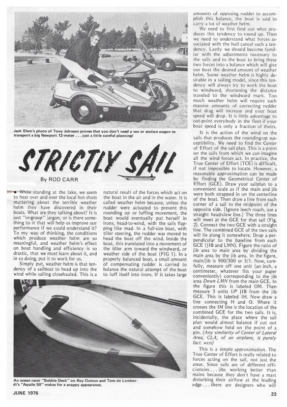
amounts of opposing rudder to accom- plish this balance, the boat is said to carry alot of weather helm. We need to first find out what produces this tendency to round up. Then we need to understand what forces associated with the hull cancel such a ten- dency. Lastly we should become familiar with the adjustments necessary to the sails and to the boat to bring these two forces into a balance which will give our boat the desired amount of weather helm. Some weather helm is highly desirable in a sailing model, since this ten- dency will always try to work the boat to <2 windward, shortening the distance traveled to the windward mark. Too much weather helm will require such massive amounts of correcting rudder that drag will increase and your boat speed will drop. It is little advantage to out-point everybody in the fleet if your boat speed is only a fraction of theirs. ba Jack Elem’s photo of Tony Johnson proves that you don’t need a van or station wagon to transport a big Newport 12-meter . . . just a little careful planning! It is the action of the wind on the sails that produces the rounding-up susceptibility. We need to find the Center of Effort of the sail plan. This is a point on the sails from which we can imagine all the wind forces act. In practice, the True Center of Effort (TCE) is difficult, By wre if not impossible to locate. However, a reasonable approximation can be made by finding the Geometrical Center of ROD CARR While standing at the lake, we seem to hear over and over the local hot shots muttering about the terrible weather helm they have discovered in their boats. What are they talking about? It is just “in-group”’ jargon, or is there something to it that will help us improve our performance if we could understand it? To my way of thinking, the conditions which produce weather helm are so meaningful, and weather helm’s effect on boat handling and efficiency is so drastic, that we must learn about it, and in so doing; put it to work for us. Simply put, weather helm is that tendency of a sailboat to head up into the wind while sailing closehauled. This is a Effort (GCE). Draw your sailplan to a natural result of the forces which act on the boat in the air and in the water. It is called weather helm because, unless the rudder were actuated to prevent this rounding up or luffing movement, the boat would eventually put herself in irons, head-to-wind, with the sails flap- ping like mad. In a full-size boat, with tiller steering, the rudder was moved to head the boat off the wind. Inside the boat, this translated into a movement of the tiller arm toward the windward, or weather side of the boat (FIG 1). Ina properly balanced boat, a small amount of compensating rudder is carried to balance the natural attempt of the boat to luff itself into irons. If it takes large convenient scale as if the main and jib were both strapped in on the centerline of the boat. Then drawa line from each corner of a sail to the midpoint of the opposite side. (Ignore leech roach, use a straight head-clew line.) The three lines will meet at the GCE for that sail (Fig. 2). Connect the two GCE with a straight line. The combined GCE of the two sails will lie along it somewhere. Drop a perpendicular to the baseline from each GCE (JIB and LMN). Figure the ratio of jib area to main area by dividing the main area by the jib area. In the figure, main/jib is 900/300 or 3/1. Now, carefully, measure off one unit (an inch, a centimeter, whatever fits your paper conveniently) corresponding to the jib area Down LMN from the main GCE. In the figure this is labeled OM. Then measure 3 units UP JIB from the jib GCE. This is labeled IH. Now draw a line connecting H and O. Where it crosses the IM line is the location of the combined GCE for the two sails. It is, incidentally, the place where the sail plan would almost balance if cut out and somehow held on the point of a pin. (Any similarity of Center of Lateral Area, CLA, fact. wen) of an airplane, is purely This is a simple approximation. The An ocean racer “Bubble Deck”’ on Ray Ozmun and Tom de Lombar- di’s ““Aquilo 50” makes for a snappy appearance. JUNE 1976 True Center of Effort is really related to forces acting on the sail, not just the areas. Since sails are of different efficiencies...jibs working better than mains because they don’t have a mast disturbing their airflow at the leading edge... there are designers who will 23
Note wide afterbody on Bill Nielsen’s Chip Bullen’s “Liberty 76” shows narrow bow “Checkmate.” sections for minimum wave resistance on wind. “Aquilo 50" shows well-rounded sections for all-weather performance. press on the hull forward of the CLR, the bow goes around. If you push aft of. the CLR, the stern moves. The hull will pivot around the CLR like it was an invisible, internal hinge. In general, when the hull is underway, the True CLR will be somewhat forward of the CLR just determined, since, when moving, the forward part of the hull works in undisturbed water, while the after part may “Checkmate” shows distinct kinship to the Flying Dutchman in her bow configuration. treat the jib as if it were a bigger sail in hopes of more nearly approximating the TCE. Different parts of the same sail provide more or less force with the leading parts of the sail being more valuable than the after parts (Figure 3). As a result, the TCE is always forward of the GCE... because the after parts of the sail are loafing while the forward parts are producing more force per unit area and are underrepresented in our GCE drawing. What we are after here is an under- standing of the Center of Effort, rather than the ability to predict how a newly designed boat will act. Through the GCE we can imagine that all the sail forces will act. The total force applied to the sail plan can be split into two vectors acting through the GCE. The damaging one is feel. This force operated perpendicular to the centerline of Hull lip on “Liberty 76" makes deck attachment easy, maintains hull shape at sheer line. the hull, and serves to tip the boat over. The beneficial one is thrust, which acts in a direction parallel to the centerline of the boat and propels it forward (Fig. 4). It is the simultaneous action of these two parts of the total force applied to the hull which will result in the boat trying to luff. But meanwhile, back under the water... The hull is resisting the sideways pressure of the wind on the sails. Whether it is a centerboard, fin keel, or full keel, the underbody is shaped to efficiently resist sideward motion. If you be working in eddies and turbulence which apparently don’t resist sideways motion so well. Now we can put the two halves of the story together. We have an approximate idea of where the sail forces act, ie, the GCE, and now we have a similarly approximate idea of where the re-«% sistance forces of the hull can be considered to be centered, ie., the CLR. In Figure 5, we see two parts of the same picture which have been separated for clarity. In (a), we see only the thrust part of the sail force, and since the sails are never actually on the centerline of the yacht, we see a lever arm labeled ‘‘t”’ through which the thrust force is able to Figure 2 Jib area — 300 sq. in. Finding geometrical Main area — 900 sq. in. center of effort (GCE) Ratio = put your particular hull in the water without the sails and push on its sheer, you will find a place that will allow the hull to balance and move sideways in response to your push without yawing. Somewhere down inside the hull in the plane of your push is a point called the Center of Lateral Resistance. If you Main _ Jib 900 _ BRIT 3 3 units Natural luffing tendency a ra Weather side Tiller movement to weather to prevent luffing Figure 1 ia 24 Baseline MODEL BUILDER
Total sai! force Figure 3 Heeling force Lae Figure 5 Figure 4 that it is almost uncontrollable. The boat in this configuration is said to have too much weather helm. The first move to cure it should be to shove the entire rig, mast and all, forward on the hull. This we have done in Figure 7. In (a), we see the thrust force producing a luffing moment as before. But look at (b). Now the heeling force is operating on its lever arm H, which is in front of the CLR. It will try to hold the head of the boat off the wind, opposing the luffing tendency of the thrust force. | think this may be hard to grasp, because we RS) Most effective have to think of a total sail force being split into two separate parts, thrust and \ \ | Less effective heel. Least effective Under the proper conditions (ie. Figure 7), each part acts oppositely on act on the hull. Remembering that the hull will pivot around the CLR, we find that the thrust vector will cause the boat to luff up into the wind. Precisely what weather helm is all about. In (b), we show the corresponding heeling force. | have placed the sail plan on the “hull, so that the heel vector operated efight through the CLR, and causes no contribution to a change in heading. In Figure 6, however, we have moved the entire sail plan aft. In (a), as before, the thrust force produces a luffing moment. However, in (b), the heeling force is no longer acting through the CLR, but somewhat aft of it by a dis- tance H. This will cause the stern to be forced around, reinforcing the luffing moment already due to the thrust force. The result is a boat which requires so much rudder to keep her from luffing Heeling force the hull. The distance H is known as ‘‘lead’’. This lead is really the length of the lever arm that the heeling force is going to act on away from the CLR. The longer the lead, the more the tendency for the boat to fall off the wind or to have lee helm. It should be obvious that a skipper will now spend some time balancing his sail plan until the heeling force moment is just slightly less than the thrust force moment. In other words, the boat will have just a slight tendency to luff up, and can be balanced with about 3 or 4 degrees of rudder offset. Just the amount available from the trim lever on your R/C transmitter. A well balanced boat should take herself to weather, with the skipper touching the trim lever now and then to allow for changes in the wind speed that the boat No change 12-Meter Class (ex-West Coast 12) he is constantly queried about the portability of the 72 inch LOA, 45 pound boat. Anyone who complains that it is too big is immediately faced with this photo of Tony Johnson and his never-give-up method of transporting his 12 to the lake. Apparently the sails come off the spars and the whole package rides comfortably beside Tony down the freeway. How’s that for ingenuity? The list of AMYA Sanctioned Clubs continues to grow by leaps and bounds, Add to your list the following: No. 54 Du Page MYC - Robert Borla, 10 W. Burlington Ave., Westmont, III. 60559. No. 55 Bermuda MBC - C.F. Langton, P.O. Box 603, Devonshire, Bermuda (Mostly East Coast 12’s, and what a site for an ACCR!). No. 56 Sydney MYC - Max Lewis, 4 Ogmore Ct., Bankstown, New South Wales, Australia. No. 57 Potomac R/C Sailing Assn. Cas Woodbridge, 3411 Mansfield, Falls Church, Virginia 22041 (Previously the sail division of the Capitol R/C’ers.). No. 58 lowa MYA - B.J. Kelch, 431 Scandia Ave., Des Moines, lowa 50315. Write directly to the contact men to find out what their regatta schedule is and to learn of the classes of boats they are Sailing. : meets. We have really just scratched the surface. We need to delve into the other kinds of changes that we can make to produce fine balance. And we should discuss the effects of heel on the locations of the true CLR and true CE, as well as the wind speed changes that have to be cranked into the system. As a first approximation, if your boat heads up too much in the puffs, move the sailplan forward. If, in a puff, the boat falls away from the wind, move your sailplan aft. Further details Continued on page 65 Luffing moment oe (b) Falling off moment of these and other mysteries will be covered later. * | must “ thank * Jack month’s lead photo. Elem for this In his capacity as Kee Figure 7 Class Secretary for AMYA’s Newport JUNE 1976 25
Sailing... 2.2% Continued from page 25 This month we will take a last look at the new 50/800’s which have popped out during the winter. Next month we will have areport on the Colonial 50/800 Regatta in which a goodly number of the boats are entered. We’ll have a chance to look back at our old predictions and : revamp our thinking. | am getting a number of calls askin for recommendations for hulls in this formula class. At the present time, | have to know a number of things before making such a guess, but the crying need in the sport is for a boat which can be competitive, and yet have had enough homework done on it to be a successful project in the hands of a beginner. The only one | know of right now is the Soling by Vortex. The price is the probable point at which a _ beginner pales, but the format, quality and proven performance of the Soling is the level at which new manufacturers must aim. For the experienced skipper, general wind strength, sea states encountered, and other vessels already sailing all have to be considered. In this case, | don’t take into account the problems encountered in building the boat, nor fitting out, nor basic trim and balance of the seagoing vehicle. A more immediate source of recommendations is your own local lake. Check with the other skippers as to what they are sailing, what they like and dislike about their boats. I’ve never yet met a skipper who wasn’t willing to talk candidly about his craft. Local weather conditions can often have a slrong ‘influence on hull choice. If you are buying your second boat and already have some experience under your belt, you should also take jnto account your own sailing style. Have you the concentration necessary to continually helm and trim a lightweight, or would you rather have a more stable, heavier boat which can be set up to take herself in the required direction with a minimum of intervention? From Bill Nielsen, in Miami, comes the Checkmate. This is the first 50/800 from Bill’s board, and no amateur he, as he earns his bread and butter by designing.power boats that people actually sit on!!! The Checkmate hull is a powerful one that will be most happy in a blow, and one that should be a joy to plane downwind, as the hull will greatly assist the directional stability in contrast to some of the machines we see. flat-bottomed racing There is plenty of room inside the hull for auxiliary controls. The suggested sail plan is definitely not high aspect, but this is in line with her heavy air capability and means that performance off the wind will be further enhanced by the sails. The ‘glas work is very good, the molded deck has a coaming forward of the hatch, and the hatch itself is generous and placed just about amidships. Some contorting may be encountered to make rudder adjustments after the deck is down, but a small extra hatch would be easy to fit over the rudder post. (Wm. Nielsen, Box 431081, S. Miami, Fla. 33143.) Also from Miami (no address at this time), is Chip Bullen’s Liberty 76. Chip aimed at the light-to-medium range with this hull, and acknowledges that the design was an amalgamation of all the best features he has observed in other boats. As a result, depending on what angle you view the Liberty from, and depending on what boats you are familiar with, you are bound to see resemblances. | particularly enjoyed the Yankee style tumblehome which appears in the after sections, as well as the sheer lip on the hull in the manner of the EC/12’s that | used to kit. The hull shape requires a two piece mold, and I’m sure that future hulls will utilize a bead of gel-coat before the two halves are mated so that the joint has the hull color right in it. This hull ts quite narrow, and | would be surprised to see her plane in any but the most fresh conditions. The result is a hull form that has been given the task of keeping both wetted surface and wave making resistance to an absolute minimum. Liberty 76 sports a single hatch with a raised lip around it. The hatch is well rounded to avoid catching a mainsheet when gybing in light air. The rudder is placed right under the transom and the bulb keel is probably the deepest currently available to balance the tall rig that Chip recommends. The Aquilo 50 was designed by Ray Ozmun and Tom de Lombardi, and made its debut in the Sandusky area last season. Ray has promised to come to the Colonial, so we expect to get a good assessment at that meeting. While a deck does not make the boat go fast, this one looks so good that it will probably psych out the opposition before the first heat starts. This hull is quite beamy, and a maximum waterline looks like it will require an all-up displacement of about 20 pounds. Ray is building a Yankee style keel shell with a rather fat cross section, and a side area of 77 square inches not counting the bulb. With all this lateral plane it should not make much leeway. My thought would be to purposely make the boat light, count on the deep midsection for leeway prevention, and cut the keel down to a minimum area to reduce wetted surface. This hull does look like it can be custom fitted out to do well in almost any wind range. Adaptations which will undoubtedly be made should make this boat a potent competitor. excellent. into the Glass work Is Much time must have gone surface finish (Ray Ozmun, 1801 E. Sandusky, Ohio 44870.) on the plug. Perkins Ave., | will be taking our new Wind II, the son of the Wind design published a month or so ago in these pages. It is an adaptation of its father, and in tuning trials, showed great promise in company with the Bingo that won last year’s ACCR. It seems that the boat likes heavy air, as we went out with a 650 square inch rig and sailed with complete control in a steady 30-35 knots during a long frontal passage. With the regatta schedule getting more and more crowded, | think we will see earlier and earlier regattas and second suit rigs will come into more common use. Remember to send your dues into AMYA, care of Secretary Bud Salika, 3917 Sunnyside Avenue, Brookfield, IL., 60513. | will be happy to field questions either directly or with a self- addressed, stamped envelope from 7608 Gresham St., Springfield, Va. 22151, or in care of MODEL BUILDER. 2