- Strictly Sail. By Rod Carr
- This text features the first installment of a step-by-step technical guide by Rod Carr on outfitting a “Yankee” 50/800 R/C model sailing yacht. Emphasizing his structural philosophy of building durable and strong vessels, Carr details initial construction procedures, including leveling the hull with custom stands to prevent warping, installing pine sheer clamps using polyester resin, and properly ballasting a permanent keel shell with six to seven pounds of lead shot. The guide walks builders through the critical alignments and installations of the forward sail control unit (SCU) mounts, the rudder tube assembly using brass tubing, and the strategic placement of Futaba radio gear and battery packs utilizing Velcro for adjustable trim ballast.

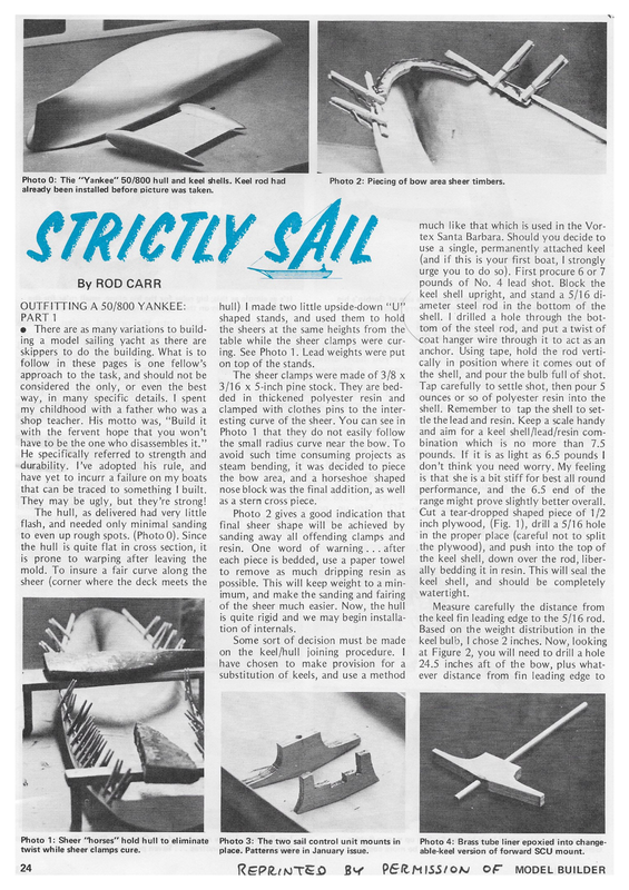
— Photo 0: The “Yankee” 50/800 hull and keel shells. Keel rod had already been installed before picture was taken. Photo 2: Piecing of bow area sheer timbers. much like that which is used in the Vortex Santa Barbara. Should you decide to use a single, permanently attached keel (and if this is your first boat, | strongly urge you to do so). First procure 6 or 7 pounds of No. 4 lead shot. Block the keel shell upright, and stand a 5/16 di- By ROD CARR OUTFITTING A 50/800 YANKEE: PART 1 e@ There are as many variations to building a model sailing yacht as there are skippers to do the building. What is to follow in these pages is one fellow’s approach to the task, and should not be considered the only, or even the best way, In many specific details. | spent my childhood with a father who was a shop teacher. His motto was, “Build it hull) | made two little upside-down “U”’ shaped stands, and used them to hold the sheers at the same heights from the\ tom of the steel rod, and put a twist of table while the sheer clamps were cur- ‘coat hanger wire through it to act as an anchor. Using tape, hold the rod vertiing. See Photo 1. Lead weights were put cally in position where it comes out of on top of the stands. the shell, and pour the bulb full of shot. The sheer clamps were made of 3/8 x 3/16 x 5-inch pine stock. They are bedded in thickened polyester resin and with the fervent hope that you won’t clamped with clothes pins to the interesting curve of the sheer. You can see in Photo 1 that they do not easily follow have to be the one who disassembles it.”’ the small radius curve near the bow. To He specifically referred to strength and durability. I’ve adopted his rule, and have yet to incurr a failure on my boats avoid such time consuming projects as steam bending, it was decided to piece the bow area, and a horseshoe shaped that can be traced to something | built. nose block was the final addition, as well They may be ugly, but they’re strong! as a stern cross piece. The hull, as delivered had very little flash, and needed only minimal sanding to even up rough spots. (Photo 0). Since the hull is quite flat in cross section, it is prone to warping after leaving the mold. To insure a fair curve along the sheer (corner where the deck meets the Photo 2 gives a good indication that final sheer shape will be achieved by sanding away all offending clamps and resin. One word of warning… after each piece is bedded, use a paper towel to remove as much dripping resin as possible. This will keep weight to a minimum, and make the sanding and fairing of the sheer much easier. Now, the hull is quite rigid and we may begin installation of internals. Some sort of decision must be made on the keel/hull joining procedure. | have chosen to make provision for a Photo 1: Sheer “horses” hold hull to eliminate twist while sheer clamps cure. 24 ameter steel rod in the bottom of the shell. | drilled a hole through the bot- Tap carefully to settle shot, then pour 5 ounces or so of polyester resin into the shell. Remember to tap the shell to settle the lead and resin. Keep a scale handy and aim for a keel shell/lead/resin combination which is no more than 7.5 pounds. If it is as light as 6.5 pounds | don’t think you need worry. My feeling is that she is a bit stiff for best all round performance, and the 6.5 end of the range might prove slightly better overall. Cut a tear-dropped shaped piece of 1/2 inch plywood, (Fig. 1), drill a 5/16 hole in the proper place (careful not to split the plywood), and push into the top of the keel shell, down over the rod, liberally bedding it in resin. This will seal the keel shell, and should be completely watertight. Measure carefully the distance from the keel fin leading edge to the 5/16 rod. Based on the weight distribution in the keel bulb, | chose 2 inches. Now, looking at Figure 2, you will need to drill a hole 24.5 inches aft of the bow, plus what- substitution of keels, and use a method ever distance from fin leading edge to Photo 3: The two sail control unit mounts in Photo 4: Brass tube liner epoxied into changeable-keel version of forward SCU mount. place. Patterns were in January issue. REPRINTED BY PERMISS/ON OF MODEL BUILDER
Photo 5: Rudder tube installation. 5/16 rod. In my case it was 24.5 + 2 = 26.5 inches. | drilled the 1/4 inch hole and then carefully enlarged it with a file to get a loose fit. This will allow room for later alignment. As soon as the keel is fitted to the hull, you will have a storage problem. So right now is a good time to stop and make a cradle for the boat. What you are really doing is making a holder for the lead filled bulb, and then contriving to stabilize the boat, which just happens to be attached. The depth of the keel will produce a rather tall boat on a stand, so remember to provide additional ateral support as shown in the drawing. This can be held on with wing nuts and by removing, will allow the boat to be stored more easily between sailings. See . Figure 3. Put strips of outdoor carpet on the vertical standards to protect the hull from scratches. Make the vertical standards of such a height that absolutely no keel weight is borne by the hull. In fact, a little bit of floppiness is just fine. Full size templates for a set of sail control unit mounts, with which we will fix the Little Hercules winch to the hull, were published last month. The front mount also does double duty by acting as the upper termination of the keel rod. Should your winch be different, modify the mounts accordingly. How- ever, height of the front mount should not be decreased, in order that the proper amount of lateral bearing surface remain to keep the keel from “work- ing’’ when the boat is heeled. |! used the old ‘“‘draw-the-bullseyearound-the-arrow”’ trick to insure that the hole through the front SCU mount -Wwas perpendicular to the top and bisected the angle of the bottom. | cut Photo 7: Futaba radio gear installation aft of winch in the Yankee. with a 3/16 inch |.D. Drill the proper size hole 5-1/4 inches from the stern keel root. The purpose is to provide as watertight a fit as possible for the keel rod, as well as having the exit into the hull above the waterline. The brass tube prevents wear from enlarging the hole in on the centerline. Drill hole in a 3/4 x 1/4 x 10 inch pine brace. Trim the brace until the tube pushed the forward SCU mount. The forward SCU mount, before trimming, is shown through the two holes turns out perpendicular to the deck line. | leave the entire tube while doing the alignment as shown in photo 5. Thickened resin is put around the tube where it leaves the in Photo 4. The installation of the rudder tube is simplicity in itself. | recommend a 3/16 inch rudder stock, so use tubing hull, where it passes through the brace, ‘ a 5.25″ wen C.G. OF HULL/KEEL 6 =@ out a 2-1/4 x 8 inch piece of 1/2 inch plywood, drilled the hole and 7/8″ pond pest then drew the template outline. Works every time, and you don’t need a drill press!!! Photo 3 shows the two SCU mounts placed in the boat. In my Case, since various keels will be mated to the hull, nee I 24.5″ — | ; See MARCH 1975 6-5/8 4 = FIG. 2 | epoxied a 5/16 inch ID brass tube inside the forward SCU mount. This is cut off flush with the top of the mount, and extends down through the hull to the bottom of a 2 inch long section of the same size Ta . . . =. . bo. Lr ese ae eae ef, e.%e . LEAD SHOT (6-7 LBS.) Figure 2: Layout dimensions for Yankee huil, keel and rudder. 25
A is ; -‘ f\\ ue | _N a> FIG. 1 25 1/8″ OR 3/16” BRASS ROD, 8-1/2″ LONG FIG. 4 (RUDDER) @- NY a NS ft TT 5/16″ STEEL ROD KEEL FIN 1/8″ BALSA SECTION 1/2″ PLY. Ge DRILL FOR PRESS SoS RU) iS FIT _ ~«| .~* ~TM Be a >. tae ee Ae : SOLDER 1/16” WIRE a — ~ COVER WITH POLYESTER RESIN, MICROBALLOONS, ETC., THEN SHAPE TO SUIT. NOSE BLOCK 1/4” PLY. and on each end of the brace itself. Remember to roughen the outside of to this arrangement in order that the radio control gear can be modularized after providing shroud mounting blocks, a mast compression strut, and jib rack the and will switch easily from boat to boat. The winch and its batteries stays with mount. The YANKEE is available from tube with a file to provide some “bite’’ for the resin to grab. (You will also note the rear sheer brace clothes- pinned in place here.) a rudder as shown in Figure 4. A good rudder is directly proportional to the amount of time you spend shaping and smoothing it. It’s not a bad idea to make a spare one too. Model Masters may be providing a rudder with the hull/keel so boat. Photo 7 looks aft toward the R/C installation. Braces such as the Using a 3/16 inch brass rod, fashion combination, each inquire specifically about that when you contact them. Prepare the hull for keel attachment by sanding with coarse sand paper, the area that the keel fin root will touch. Do any necessary shaping of the top of the fin root so that it blends nicely with the hull. Final fairing will not cover up gross errors if allowed here. Insert the keel rod up inside the hull, and slip the forward SCU mount down over it. Mark how much of the keel rod protrudes out the top of the forward SCU mount. Cut the rod down until ones holding the rudder tube are used, and 4 sheet metal screws mount the radio board to the braces. The batteries for both the winch and R/C gear will wind up being wrapped in Velcro, with a Velcro strip placed down the center of the bottom of the boat. This will allow shifting them as trim ballast. Next month we’ll put the deck on, MODEL MASTERS manufacttring division of LEISURE PRODUCTS, 6920 Braddock Road, Annandale, Virginia 22003. The hull/keel set costs $50, and is shipped FOB Springfield, Va. by UPS. Write to them for further information. And write to me, Rod Carr, 7607 Gresham St., Springfield, Va. 22151, with your questions and suggestions. I’d like to hear of some methods you use for making hatches that are watertight. I’m running out of masking tape!! 7) FIG.3 only about 1/2 inch is left, above the mark. That half inch needs to be thread- ed with a 5/16-18 National Coarse thread. Mix up a batch of resin and coat the top of the keel root and the bottom of the forward SCU mount. Assemble and tighten down the 5/16-18 nut to hold the whole assembly together. Place on the cradle and check for alignment. Wipe excess resin away as before. Photo 6 shows the Little Herc winch in place. The wiring diagram for the winch/servo combination will accom- pany next month’s article. We have gone 26 MODEL BUILDER