- 36‑Restricted Class Championship (1964). The national championship at Bournville attracted only six entries, highlighting already‑declining participation.
- A major instructional feature on “Petrel”, an 18‑inch sailing cruiser:
- Explains why true scale sailing models are difficult due to scaling laws.
- Introduces bread‑and‑butter hull construction using lines plans.
- Step‑by‑step guidance on interpreting sheer plans, waterlines, buttocks, and body plans.
- Focuses on learning to work from professional drawings rather than kit assembly.

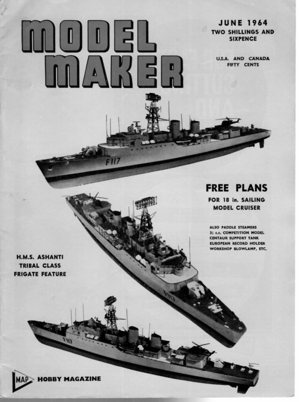
JUNE 1964 TWO SHILLINGS AND SIXPENCE U.S.A. AND FIFTY FREE CANADA CENTS PLANS FOR 18 in. SAILING MODEL CRUISER ALSO PADDLE STEAMERS 3; c.c. COMPETITION MODEL CENTAUR SUPPORT TANK EUROPEAN RECORD HOLDER WORKSHOP BLOWLAMP, ETC. H.M.S. ASHANTI TRIBAL CLASS FRIGATE FEATURE HOBBY MAGAZINE a
1964 36-Restricted Championship Veteran “Mickey” wins once again from field of only six entries. By J. L. Woollam sistency of the father-and-son-sailed Chance II] which averaged about 11 points per round. Lunch at around 1 p.m. was a pleasant break enjoyed by all, and when sailing recommenced an hour later for the last round, it became clear that Quackie would not be able to improve her position enough to challenge Mickey, who finished the race a clear 12 points ahead. Thanks are expressed to O. O. D. Hardwicke and the Starter, D. Lippett, not forgetting Mrs. Lippett on the catering side, who all helped to run an enjoyable and happy race. Incidentally, the tea is warm and good and strong at only 3d. a cup at Bournville. Any offers? Round Reg. 372 HE 36R National Championship, held at Bournville on March 28/29th, had only half a dozen entries — three from Bournville, two from Clapham, and one from Birmingham. Without the Clapham entries of Messrs. Gorst and Dicks, to whom thanks Racing started at 2 p.m. on Skipper ist 2nd Posn. 3rd 4th Mickey A. Cole 20 43 58 °*T4 1 612 Quackie E. Gorst 15 26 46 63 2 936 Jean III B. P. 15 30 40 £52 3 675 Chance III P. Salt 13 23 34 44 4 972 Poco W. 10s) 214 28-3795 5 Ken I. 2 in 38 6 1028 are due, the Championship may not have been held. Yacht E. Hayward Dick Cooke 130 Above, “‘Quackie”, being walked off by the mate, appears to have a fair lead on “Mickey” in this run. Below, ‘“‘Mickey”’ again, this time ahead of ‘*Chance IID’. Saturday, and two rounds were sailed before it was called a day. The wind was very light and patchy on the water, and although spinnakers were used they barely filled. Mickey, three times champion, just drifted into the lead with her almost 1,000 sq. in. of sail. The two Duck-bow boats of the race, Quackie of Clapham and Jean III of Birmingham, were continually swapping 2nd and 3rd place in the scoring. Quackie has a slightly finer bow than Jean III, and the fore edge of her keel slopes rather further back. On Sunday. when racing started at 11 a.m., the wind had strengthened and was changing to more of a reach. Saturday’s leader Mickey, yielded her place as highest scorer to Quackie in the third and fourth rounds, and also noticeable was the con- ELECTRIC RECORD BOAT [Continued from page 279] A charger for the accumulators is essential; it is never satisfactory to have them charged in a garage, etc., as they need careful attention to prevent any In Addition All wire leads should be made from 2 mm. well insulated copper wire. Finer wires would heat up rapidly due to the high current flowing. Leads should be fitted with sturdy terminals which can be clamped securely to the motor and accumulators. Motor and prop shafts must be absolutely straight and in line, with no possibility of binding or friction. A rigid joint with a single connector is recommended; a piece of silver steel tube about 13 in. long with three holes at each end tapped 6 B.A. for grubscrews is excellent. Flats for the grubscrews can easily be ground or filed on the shafts, and there is no possibility of distortion or coupling slip. peony of overcharging and consequent shortened ife. The C.G. of the boat can only be established by thorough tests, and it can only be said that it lies in the rear third of the boat. Paintwork of the boat is the last job of all, and all tests should be carried out before the final finish is applied. I hope that some of the foregoing will prove useful to potential electric users, and that I may perhaps have encouraged one or two readers to try a fast electric boat. 276
JUNE PETREL 1964 An attractive little sailing model which is an exercise in working from a lines drawing, shows the technique of bread-and-butter construction— and introduces thoughts on scale sailing boats A NUMBER of requests for “scale sailing models” are received at Model Maker offices, but it is not yet generally appreciated that a scale model of a full-size yacht or dinghy is not really a practical proposition, even for those who do not expect 100 per cent performance under all conditions. The reasons are not far to find; consider a quarter full size scale model as a simple example. The length will be a simple linear scaling down, i.e., the model will be one quarter the length of the prototype. Sail area, however, will be 4 high and 4 wide, or jth of the prototype, and displacement and other cubic measurement will be 4 x 4 x 4, or aith of the prototype. In a displacement type the fixed ballast may well be two thirds of the only any only hull, total weight; our model therefore has ;) sail area with its centre of effort 4 high, but the ballast, although its C.G. will still be 4 low, will only be #: of the fullsize. A dinghy type hull, with perhaps a centreboard but no fixed ballast, relies on the agility and weight of its crew; even if we arrange an automatic crew dummy to swing about, it will only be ez full-size weight. On the face of it, the simple answer would seem to be to make the dummy crew eight times heavier, or to increase the ballast in a displacement hull. However, what does increasing so large a proportion of the total weight do to the waterline? Obviously, it sinks the boat far deeper in the water, so that scale appearance afloat is lost, and so is any hope of even a moderate performance. There is no simple way round the problem — in fact, there is no real answer at all. Compromises can be made which are acceptable to most people, and the aim of these is usually to preserve scale appearance above the waterline, either by distorting the lower hull shape or attaching for sailing an additional member in the form of a relatively large and ballasted fin/keel. The alternative is to select a form of prototype which minimises the alterations of ratio, and to design from it a model which retains the general characteristics. Such a project is Pefrel, the subject of this month’s full-size plan, which also introduces a Ss series on construction of bread and butter hulls. It has always been our belief that the average modeller likes to learn as he models, and we know that most when confronted with a lines drawing tend to blink and look away, though a lines drawing is so simple to use when the penny drops. We have therefore drawn up this hull so that most of the steps are completed, yet enough remains to initiate the builgler into what he might feel are the mysteries of working from lines. This month’s article is concerned only with making the basic hull. A popular type of yacht is the sloop or even cutter-rigged cruiser of 5-8 tons, with an overall length of 28-36 ft. and a waterline of 20-27 ft., offering accommodation for two, three, or four people. Our model, Petrel, is fairly typical of the traditional approach to this type of craft, and a glance through any full-size yachting magazine will usually provide drawings or at least photographs of similar. vessels. Deck layout, etc., is relatively unimportant to our model — for example, the coachhouse could be extended forward and the mast stepped through it, for additional cabin headroom — so that any deck arrangement on similar lines can be followed for a handsome semi-scale model. Details of our own deck layout and the Bermudan rig will follow next month. Construction A lines plan consists normally of three views, a profile or sheer plan, a waterline plan, and a body plan. The first of these is a side view of the hull, with horizontal straight lines and vertical straight lines, plus some curves. The horizontal straight lines represent the waterlines, and if you visualise these as slicing the hull into layers, each layer will be slightly smaller (in general) than the layer above, because the hull gets shorter and narrower the lower you go. If we stack the layers one above the other, by looking down on the stack we shall see the shape of each layer superimposed on the one below, and that is exactly what the second view, the waterline plan, shows us. Since the hull is symmetrical, it is only necessary to show half of it; the other side will obviously be the same. On the waterline plan we once again have vertical and horizontal straight lines, and the horizontal ones can be considered as cutting the hull into vertical layers; the shapes of these layers looked at from the side are the curved lines in the profile view. They are usually called buttock lines, though this is not entirely correct, as the buttocks are strictly the aft quarters and the forequarter shapes should be called bowlines. The vertical lines on both these views “cut” the hull into sections and the shape of these sections is shown on the body plan. Normally the sections forward of the largest are shown on one side of the centre line, and the sections aft on the other side of the same line, but to fit them in conveniently on our It drawing the two halves have been separated. will be seen that the vertical sections have been numbered 1-5 and T (for transom), the buttock lines X, Y, and Z, and the waterlines A to J. Any point on the hull can be measured accurately by reference to two views, using the third view as a check. Bread and butter construction, in which the wood is the bread and the glue the butter, is the usual term for laminating the hull from sawn planks and carving the resulting block to shape. It may be on the waterlines, i.e., horizontal laminations, or on the buttocks, using vertical planks. Our drawing is shown with waterlines spaced at 4 in., ie., calling for 4 in. thick planks; the buttocks are shown at ? in. spacing, so that anyone wishing to “bread and butter on the buttocks” would need #% in. planks. To use horizontal planks of 1 in. thickness would 285
SHEER PLANK Xx a \ e I X j i ae Z he E AFT BODY PLAN X id La oar Pemrgeatl 50 Ripe Yphonies 4 Kd = OE rratet Te e es |Reape oe ee “gis ; \ \ L | i aes a Ee / ae Serle pre si / 7 a 4 ah ee wf | Se AND RIGGING DETAILS WILL APPEAR NEXT MOKITE SHEER PLAN ae aes. WATERLIN THICKNESS Ses OF FINISHED HULL SHOWN AT EACH STATION BY DOTTED LINE ZO
| COCKPIT & RUDDER D 0 Pe if we Se areas EE Sfetetetetesesesesese OE seatsMPEP Stet eet PESTS ESERIES Se De tere terereleteteteseieteletetetese Tlelepeleleletelesesdiesesester SOMO ) | pone eran foe 3 epi, oo ae 2. — OFF Le et ie be het he tet Be ee he ee ee Re J oe SHADED PORTION IS 3 EXTENT OF BALLAST, CARVE IN HULL SHAPE INITIALLY ie J nae are \ BASIC HULL FINISt LINE, RUDDER IS SI Se SS EEE J bo BG
TT rs ra WMONGEL IMIANKIER! mean omitting every other waterline, to use 4 in. would mean drawing in waterlines between those shown. Any thickness of timber can be used, in fact, by drawing horizontal lines at the same “thickness’ across the body and sheer plans and marking out waterlines by using a pair of dividers to measure the width of each section where it crosses the pencil lines on the body plan and transferring the measurements to the appropriate section line on the waterline view. The points marked on each section line can then be joined with a curve, keeping a family resemblance to the curves already there; where the lines ‘begin and end can be measured from_ the pencilled lines on the sheer plan. Additional sections can be plotted on the body plan by a reversal of this process, and similarly, extra buttock lines can be drawn if desired. To build the hull as intended, horizontal 2 in. planks will be needed, and for a model of this size and type balsa is entirely suitable. Two % x 4 x 36 in. sheets are all that is needed, since we shall cut out the centres of all the upper planks, to economise on wood and to save a lot of hollowing at a later stage. Each plank above waterline F will be in two halves, cemented together before assembly. : First trace the outline of the biggest plank, waterline A, including the section station lines — see sketch on plan. Section 3 has been drawn out to show what the actual sections of the planks will be before carving, and it will be clear from this how much of the centre can be cut away. With dividers, step the inside dimension arrowed on to station line — 3 on the wood. Do this at the other station lines the approximate thickness of each hull section has been dotted in on the body plan. Now trace the next waterline, B, and place the tracing over the marked out plank A, aligning its outside shape approximately with the inside cutting marks. Using this outline and the marks, plus a bit of intelligence, it is easy to draw the inside cutting line for plank A to ensure sufficient overlap with B. Cut out A and save the centre for the biggest lower plank that will fit it. Follow this procedure for each plank. A fret-saw is the best tool and with accurate sawing there should be no need to sand the planks at this stage. Cement the halves of each upper plank together and, most important, mark the centre and station lines clearly on all faces. When all planks are ready, lay plank A on a flat surface and cement in BURNER the handle everything parallel to [Continued from page 290] and the cross tube. After making sure is square, bend the cross tube until it is the handle. Repeat this procedure for the other side so that the burner ring will now slip over the ends. Trim the tubes until the distance between the end of the handle tube and the outer end of the burner ring when fitted is approx. 1% in. and then solder or braze the ring in position, taking great care not to block the pilot jets when doing so. Now grip the handle tube in the lathe chuck and true the ring up concentric to the handle by tapping with a hide hammer. Whilst it is still in the chuck, drill down the centre with a zs in. drill to take out the cross tube and allow gas to the pilot jets. If this operation is done before this stage, a strain is placed on the soldered joints when the tubes are place plank B, aligning on centre and station lines accurately. Follow with C, D, etc., and leave the stack under weights to dry thoroughly. A “short” sheer-plank will be needed on top of A, running from the bow to halfway between stations 2 and 3, and a scrap will also be needed at the stern; these pieces are best added last, after the rest is dry. When the stack is thoroughly dry, the corners of the planks can be carved away, both inside and outside. The inside need not be carved absolutely smooth, but it is nice to have a good-looking interior. In any event, most of the surplus wood should be removed. Theoretically, when the corners on the exterior have been smoothed away and the hull sanded down to the cement lines, the finished shape should be correct. It is unwise to rely on this, however, and thin card templates should be cut from tracings of the body plan sections to check. Between stations the shape should be sanded to a smooth blend by eye, a process which requires a little art, is one of the most pleasant phases of building, and separates modellers from mechanics! The sheerline (curve of the deck edge) should now be marked on, measuring up from waterline B, and the edge trimmed. A coat of clear dope will harden the exterior surface and leave the hull ready to be tissue covered. There is a choice of deck, either flat (from side to side) or cambered, and dotted on the section drawing is a typical deck beam for a cambered or curved deck. It is helpful to fit the deck-beams at this stage, but to do so it is necessary to know the Suggested positions are at ultimate deck layout. Station 1, 2 (i.e., just ahead of the mast position) and 5, with one halfway between 3 and 4 which can later be cut away if desired. The beams should be cut from 4 in. hard balsa, hardwood, or ply, and “halved” into the thickness of the inwale, i.e., the inwale will be notched about & in. deep and the beam end cut to a snug joint. A flat deck is simpler in that the beams will be straight, but the appearance is less attractive. The inside of the hull should be varnished or given several coats of shellac, banana oil, or thinned paint. [To be continued] To make up plan, lift centre wires and remove pages 286 and 287. Cut out page 289, locate accurately, and tape to page 287. bent. Having done this, all that remains is to screw in the jet, connect to the gas and test. If for any reason the torch strikes back whilst in use, all that is necessary is to blow sharply across the gap between the jet and burner ring and the flame will jump back to its correct place outside the ring. Pilot jets are essential as there is too much air for it to burn on its own and coning the end down only makes it strike back. A refinement would be to include a small gas cock between the main jet and the point where the pilot tubes enter the main tube; this would mean lengthening the pilot tubes, but would enable the burner to be shut off during pauses in work without the necessity of re-lighting (the pilots would continue to burn) with consequent economy in gas. 288
DETAILS ETC. FORE BODY PLAN AONTH x aes 2 eyeana e l =. INS TRANSFER INSIDE DIMENSIONS AT EACH STATION AS THIS EXAMPLE eee NOTE INWALE THICKENED SLIGHTLY . AT THIS SHES BL f.\} on oN 3 a| fe.A ah SEPARATE HALVES STATION 3 5) DK. ALL PLANKS ABOVE WATERLINE ‘F’ CUT IN TWO HULL & PLANK SECTIONS AT fe Ve : HULL (oes ee ds SR eR ee gh / a= ®m® F _E D C HMMM PLANKS BELOW WATERLINE ‘F! CUT FROM SOLID


