- Radio Control for “A” Class Yachts. By G. Honnest-Redlich.
- Sun-Kiss Marblehead. An American champion with sliding rig, By A. R. Lassel and T. Thorsen.
- A Model Ice Yacht. By A.M. Colbridge.
- Radio Introduces Racing Tactics to Model Yachting Part 2. By Col. C. E. Bowden.
- Designing to the “A” Class Rule, Part II. By B.H. Priest.
- Model Yacht Club Notes. By “Commodore”.

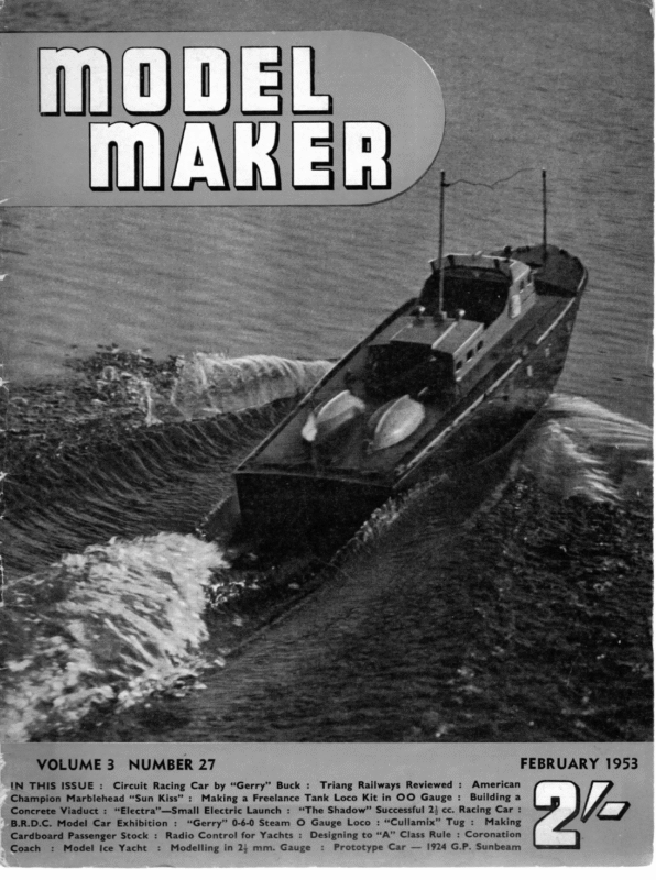
VOLUME 3 NUMBER 27 IN THIS ISSUE : Circuit Racing Car by “Gerry” Buck : FEBRUARY 1953 Triang Railways Reviewed : American Champion Marblehead “Sun Kiss” : Making a Freelance Tank Loco Kit in OO Gauge : Building a Concrete Viaduct : “Electra”—Small Electric Launch : “The Shadow” Successful 2} cc. Racing Car : B.R.D.C. Model Car Exhibition : “Gerry” 0-6-0 Steam O Gauge Loco : “Cullamix” Tug : Making Cardboard Passenger Stock : Radio Control for Yachts : Designing to “A” Class Rule : Coronation Coach : Model Ice Yacht : Modelling in 2 mm. Gauge : Prototype Car — 1924 G.P. Sunbeam
Radio Control for A Class Yachts og § (Sr HONNEST-REDLICH OME time ago in an article in the MODEL MaKeER, I campaigned for R.C. yachts, of the racing classes. The response had up to a short time ago been rather slow, in fact, for nearly three years I have found no one to compete with. Recently, however, that versatile R.C. enthusiast, Col. C. E. Bowden, has started the ball rolling again. Competitive R.C. sailing between his ten-rater and my “A” class have not only opened a new vista, but the demonstrations have won adherents amongst members of yachting clubs. In 1953 we shall definitely be able to hold competitive yacht racing radio-controlled. For this purpose commercial equipment will be available which, for the first time, will enable several models to operate together, still using the allocated R.C. frequency. This will not affect the present type of radio receiver which is used in our yachts. This is the three-channel tuned reed equipment, which after various tests appeared to be the only means of giving instantaneous rudder control over any chosen fractional movement up to full helm without having to go through any unwanted sequence positions. The sail operation is again quite independent. This is not to say that the cheaper receivers cannot be used, but. the speed of control and furthermore, the positional accuracy required, would outclass them in competitions. For example, a rudder capable of fractional movements will enable a yacht to sail closer to the wind than one with a positional rudder movement. For purely non-competitive sailing, the cheaper R.C. equipment, followed by a system of mark-space ratio, would also be suitable, with, however, the extra complication of a circuit for sail operation. The third channel was used to operate an electric-motor-driven three-positional mechanism. The three corresponding sail positions being: tacking, reaching and running. Having really fingertip control over the rudder, there is not the usual necessity to have accurate sail positions. In fact I have operated a Marblehead yacht by rudder only, leaving the sail in a position between tacking and reaching. Now to the general layout and installation in the yacht. A yacht hull is not very suitable for permanent wiring and fitting of equipment, therefore I decided to fit the entire radio, batteries, rudder and sail mechanism, plugs, switches and all wiring in a self-contained box which is dropped, flush-fitting with the deck, into an opening just aft of the mast. This method is becoming accepted as general and devotees now equipping their “ A ” class yachts | Complete Rad: & Battery Box Using the E.D. three-channel equipment, the choice of methods was after exhaustive tests, as follows: Two channels were used for an electric-motor-driven steering control, this gave an instantaneous control in either direction, and the steering lever on the standard transmitter control-box could be operated as if it were the tiller itself. CONNECTION TO CONTROLS
ies wees CONTACT SPRING GEAR TRAIN the phosphor-bronze or spring-brass contact strip act as a travel limit switch, should be chosen to allow the lever to come to a stop at these positions. If the slots are too short, the overrunning of the motor may carry on to the next section. The direction of retention should be chosen so that the sheets are hauled in when the crank-pin moves above the centre. More power is developed on this stroke, less on the next half rotation which lets the sheets out. The lever arm should be of dural or brass of a section strong enough to prevent any bending, or alternatively of a channel section. The motor and gearing required should be according to the size of yacht and sail. Up to ten-rater size, an “Eveready” or “Frog” miniature type geared to give a full lever movement in 24 seconds is quite suitable. For “A” class yachts, however, in order to obtain a 24-second full operation, a stronger motor is required. SAIL MECHANISM with R.C. are using the same sized box to enable an easy exchange of equipment from one yacht to another. Rudder control is by a short lever projecting through a slot in the box cover. This lever travels about two inches in a forward-aft direction. It is coupled to the rudder-arm by a stiff wire or rod. The sail mechanism required a little more thought, and let it be mentioned a lot of actual tests under operating conditions. The use of a rotating drum was found to have a lot of drawbacks. Cords got snarled up, knotted themselves, and unless there is some method of taking up slack, it should not be used for racing yachts. It is not easy to devise a simple slack taking-up means without using up space and adding further complications. I, therefore, decided to use my motor-operated positional equipment to move a lever, again through a (Continued on page 118) ‘STRIKER’ paxolin for Limit Switches SPINDLE LOCATING TRAVELLER fore and aft slot in the box-cover. The means of attaching the sheets can be seen from the sketch. Both steering and sail lever slots have thin pieces of sheet-rubber covering them, and the levers move through a slot in the rubber. This and a rubber gasket between lid and box make a nearly watertight job over which water can wash without causing any trouble. However, remember that waterborne radio needs attention and care. Firstly, plugs, sockets, switches and contacts, everything in an electrical circuit which is not soldered can tarnish and corrode. Frequently inspect, scrape clean plugs and sockets, emery switch contacts, and a light oil brushed upon metal parts, except the contact surfaces themselves, will keep your radio in LIMIT SWITCHES\\ bronze or brass spring strip with silver contacts rivetted on LEAD SCREW 4 BA, studding with ends turned down just below 2-4 B.A. Nuts soldered to Operating Arm depth of thread _. RUDDER MECHANISM reliable running order. 78 oe The amount of power required to haul in the sheets of an “ A” class yacht is quite considerable, even a ten-rater in a strong wind requires a robust mechanism well geared down. The chassis or gear-case, the crank and pin, and the final operating lever must be quite substantial. The skeleton drawing shows clearly the general method of assembly, remembering that although the gears at the electric motor end of the train can be ordinary clock types, the final drive gears and spindles should be quite heavy types. The length of the cut-outs in the crank-flange, which in conjunction with ee £ — ”~ OPERATING < ARM
J. Weeks of Bristol with his February 1953 yacht “Fandango,” at the 1952 B-r-i't is h Nationals at Lake. yacht “ SUNKISS ” Witton is This an exact replica of “Sunkiss” — though the sliding rig was not used as such for the National AN RIG AMERICAN BY A. event R. MARBLEHEAD CHAMPION WITH LASSEL T. & SLIDING THORSEN This fine boat can be built entirely by either conventional bread-and-butter or planking methods, which have been described in this magazine. The article is therefore devoted to a description by the designer of sailing with his remarkable sliding rig. This will be completed in the next issue, when the latest type of Lassel Vane Gear will || be illustrated sails in a definite relation to each other. The ever-present measuring means, finger-breadths, is used so as to improve on mere guessing. We haul in on the synchronous bowser snug, bringing the boom in about midships, and ease up on the jib-sheet adjustment so that there is a space equal to three fingerbreadths between the mast and the clew of the jib, in the case of an “M”; for an “X,” four units and for an “A,” more commensurably with the length of its club. This set would be suitable WE _ assume that your model yacht for a 14-mile wind; in stronger winds haul the synchronous bowser tight, not just snug. In lighter winds, ease up on the bowser in steps corresponding to the gradual decrease so that, in drifting zephyrs, the bowser has moved an inch from its original place. If the yacht then would be picked up and headed into the wind, the sails should begin to luff at the same time. Preferably, the jib should luff before the main, and, particularly, its upper corner, the head, should have its belly deflated in the first stage of luffing. To maintain that deflation is the ideal of steering; it is the consummation of the skills in design and yachtsmanship; it is the best possible index of your proficiency. Watch that index! A parallel aboard a full-rigged ship, as a guide for the helmsman, is the action of the wind at the weather corner of the mizzen royal (the topmost sail on the aftermost mast). The yards are braced around in a high-pitch spiral, so that the higher the sail, the earlier it luffs upon the ship heading in to the wind. The helmsman keeps that corner deflated, no more, no less, and days on end, in the South-East Tradewinds, where the winds are constant. is equipped with vane steering gear and sliding rig, on which the sheets are rove so that one bowser simultaneously controls the set of the two sails. That bowser has been called the “Synchronous Bowser.” The standing parts of the sheets are sliding with the rig and are attached to either a jamming ring or an adjustment bowser. The main sheet is single-rove, but the jib-sheet is double-rove through a fairleader approximately half the distance to its jib-tack swivel as compared with corresponding elements of the main sail, which results in both the boom and the club maintaining about the same angular speed as the synchronous bowser is being moved. The major axis of the pond is assumed to be parallel with the wind, and that we experience a beat to windward at the onset of our adventure in sailing. So, we proceed to set the yacht to sail close-hauled. Our immediate attention is to set the two 79
~ SUN KISS DESIGNED BY M TTHORSEN & A LASSEL p M COPYRIGHT OF MODEL MAKER 38.CLARENDON RO PLANS WATFORD. SERVICE ; z HERTS. 08 _ "SLE a crane fot etreoor ninien mca aa ieee till
Not blessed with such winds on our ponds, we have to put up with up-draughts and downdraughts. To preserve his assurance, the skipper must evaluate the vagaries of a down-draught realistically. If such a jet is being funnelled down to the surface of the pond, it ruffles up and darkens the pond’s surface and fans out. Thus, if two yachts are sailing in the same lane but some feet apart encounter such a flaw centring between them, the leader will head up and the other will pay off with reference to the course sailed the moment before. So, that incidence was just one of those things, and there is no need for new sails, fuller garboards, smaller skeg, or larger rudder. The next thing to come to our attention is the sliding rig. It is an adjunct to the vane steering gear, which is by no means all-suffi- as to tip the centre of effort either ahead or aft. This system, although having limited merit, fails when the strength of the wind requires sheeting the jib flat amidships and, often, easing up on the main. The spectacle here is an excessive heel, no snap, and an inordinate. induced drag caused by side-slipping. Next the vane has to be set. The self-tacking gear is assumed. It has five “triggers”; the Locking Latch, the Plunger, the Symmetry Adjustment, the Cams and the Tension Slide on the oscillator arm. The latch either locks the “ Seattle Bar ” (the combined friction clutch and oscillator bracket) to the vane-disc or to the vane-frame. The latch, down and locked to the disc, aligns the Seattle bar ideally with the centre-plane of the yacht and allows the flip-flop of the feather assembly, so that the leading edge of the feather may look into the wind’s eye over either bow with- . cient. The rig is set to correspond to the lightest wind expected on the windward board. With an increase of the wind, the rig is moved ahead, and the spaces traversed in sympathy with the wind resemble the D-scale of a slide rule. The seven-inch scope allotted is rarely enough, the idea being that when the forward end has been reached, it is time to reduce the main sail. Should the rig lack scope in the aftermost position, lee helm must be used, but such expediency is only justified to supply this limited deficiency. Lack of scope in the foremost position calls for stepping the jib farther ahead, or, as last resort, for sheeting in on this sail for the purpose of tipping the centre of effort ahead; in other words; “choking her to death.” However, the sensible thing to do would be to start reefing the main. Equally sensible, perhaps, would be the striking of the jib instead of using lee helm in a drifting match. The sliding rig affords a quick means of “ Tuning up” and re-tuning to conform to the wind changes. The skipper should develop a built-in aerometer behind his eyes; it gives him assurance. If the jib, by shaking too frequently, announces that the yacht is trying to lie too close to the wind, slide the rig ahead half an inch or so; if it stays “asleep,” slide the rig aft until an occasional deflation takes place. As our system of sailing has been outlined, it differs from the usual “ toyboat sailing” in as much as in this case the jib is sheeted so out manual intervention. This ability of the gear to set itself as the yacht is tacked justifies the designation, self-tacking vane. The latch, hinged up and straddling on the feather frame, locks the latter Seattle bar, which, through its friction transmits the torque from the feather the lug to the clutch, to the in sailing full and by. The latch, hinged up without straddling the lug, is used in effecting a “ quick gye.” In a gye, the yacht heaves about without direct help from her handlers. The procedure is to raise the latch, before turning the yacht about, so that the flip-flop of the feather is impeded in its full-amplitude travel, then the yacht is put about low in the wind so that she may gain momentum ample for the manoeuvre. The quick or short gye will give the yacht eight or ten feet of offing, which may enable the yacht to fetch the finishing line without sailing the width of the pond. (To be continued.) 81 eee vane-arm. That expediency is used in sailing all courses other than lying close; even preferable wwerteetin ee er SE oats Sliding rig as fitted to “Fandango.” Note that jib is attached in conventional manner as in this instance the yacht was sailed without using the special rig (in the absence of these tructions at the time!)
MODEL MAKER practice strokes on waste card are always advisable to check paint consistency, pen setting, etc. Transferring or hand-lettering complete the finish, with the exception of attention still to be given to the ends. Windows can therefore be inserted, but only after it is certain card steps, eic.; if a bowed end is involved, sheet timber or a CCW bow-end component is glued in position in place of the cartridge paper and is then shaped to suit the model. Finishing the Coach It is hardly within the sphere of these notes to describe the processes required to complete that edges of the inner walls have been coloured Where they are visible through window apertures. the vehicle and make it ready for service and it will therefore suffice to say that this can be done by the addition of solebars, buffer beams, Completing the Ends With the windows in place, each end should be covered with strong cartridge paper: as this truss rods, batteries, dynamo, buffers, couplings, vacuum pipes, corridor connections, bogies and must cover the entire end of the coach, the ends of the window channels and the end of the roof, it is advisable to fit a paper which is over- whatever other items are appropriate to the prototype concerned. As a final word... do size in every direction and trim it when it has been secured and the glue has hardened. A remember that where a main line train repre- it is desired first to fit such end detail as tiny carefully lettered in Indian ink on good card can make just that final difference! sents a named unit, the addition of name boards coat of black paint is added at this stage unless SS = A MODEL ICE YACHT (Continued from page 87) drilled in the body at the appropriate angle and braced with a forestay and two main stays to each end of the track beam. Mast and sail can be made detachable as a unit. For normal operation the tiller can be held in the central position by means of a rubber band. This will provide slight, but smooth, hard sand. Almost any relatively smooth surface will do, however, provided the area receives a reasonably true wind and is not blanketed by buildings. For best results with the wheeled version, use relatively large diameter wheels of the rubber tyred variety. necessary, rudder action when the ALL BLocKs wwe yacht is under way, adjusting the tension in the band to suit. You can, if you want to “ experiment further, fit a yacht type quadrant to the spindle carrying the front rudder, coupled up to a suitable control horn on the sail boom. This will provide compensating rudder when a gust of wind heels the yacht over. to overdo this However, it is easy steering action as the offset front runner will have a strong effect on directional control. In other words, if you do try this form of automatic steering, start by limiting the actual “rudder” movement to quite a small amount until you can find how this works out in practice. All told, you should have a lot of fun with this simple ice yacht— first with runners when the local pond is frozen over and then, later. with wheels. Just about an ideal track for the land yacht version is RUNNER FRONT ONNER r: LE
‘TBs unusual project is actually a semi-scale model of a racing type ice yacht, popular in the North American continent during the winter months when lakes and large tracts of water are frozen over. For the model you need the frozen surface of a suitable pond which, if promise of a hard winter is fulfilled, should not be all that difficult to find! But your model, once complete, is not necessarily restricted to limited winter operation. You can get very much the same results on land, by replacing the runners or skates with wheels. Best results will, _COLBRIDGE however, undoubtedly be achieved on ice. The main drawing gives all the basic dimensions required. Marconi-rig is used, with a single sail. This is employed with a sharply raked mast, for stability. The full rake of the mast at the tip is actually nine inches from the deck position. Three-point suspension is used, with the main runners having a wide track, also necessary for stability. All three runners are pivoted and in action in a strong wind the model will tip to one side and travel on just one side runner and the front runner. ‘Unless the runners are freely pivoted the yacht will tip right over once one of the main runners is lifted off the surface. Start construction with the body. Cut two triangular pieces of } in. balsa, each 18 in. long and 14 in. wide, as shown. To one, cement on four balsa blocks, each 2 in. long and 4 in. high. These blocks are shaped to the taper of the bottom panel once set. Note carefully the spacing of these blocks as these form necessary strong points for attachment of the track beam and mast. Complete the body by cementing on the top triangular piece and then the two side pieces of in. balsa. wire leg with soldered washers each side to retain the runner properly. Use flat washers soldered close up to the runner so that it has no appreciable side play. The leg is housed in a length of brass tube which acts as a hinge fitting, the top of the wire being bent backwards in the form of a tiller. The tube is secured to the front of the body by binding in place with gauze thoroughly soaked in cement. Once all three runners have been fitted in place, stand the assembly on a flat surface and check that all three runners are contacting the surface evenly. Any rock will upset the stability of the completed model. Then lift the model off the table, rocking to one side and then the other and check that the runners pivot smoothly so that, when sat down upright again, the free runner automatically assumes its correct attitude. You may find it advisable to fit stops to limit the movement of the two main runners to prevent them “ digging in” when the yacht When set, sand down and round off the rear end to a nice curve. The track beam is made of generous size, tapered from 2 x 3 in. stock as shown in the diagram. For preference use a light hardwood. Screw and cement to the bottom of the body so that the centre of the beam is 44 in. from the rear end. Make sure that the beam is square with the body. The runners can be cut from 1/16 in. dural. They are rectangular in shape with the front ends rounded off. Suspension of the main runners is by means of small metal brackets screwed to the underside of the track beam at each end. A 6 BA screw can be used to give a good, rigid pivot for the runners. Tighten up so that the runners have little or no side play, but pivot freely. Note the exact location of the pivot hole. returns to an even keel after heeling over. The sail plan is given on the main drawing. Cut the sail from the best material available— model sailcloth, for preference, and last to boom and mast. A length of 3/16 in. dowel can be used for the boom. Actual length of the mast is 23 in. and this should be tapered from 2 in. diameter at the bottom to about 3/16 in. diameter at the tip. It is located in a hole (Continued on page 86) The front runner is assembled on a simple 87
MAKER es Radio racing progresses, we may perhaps introduce a few more. My seven rules could perhaps be Introduces considered by the Model Yachting Association and, if agreed to, might be published, so that we can all start off on the same foot. I detail these rules below in simple language for the beginner—see accompanying sketch to understand main racing terms. RACING TACTICS RuLe 1. A yacht on the port tack (i.e. wind coming from left when beating close hauled for the purpose of this rule) must keep clear of a starboard tack (wind coming from right) yacht when crossing tacks. This is done by the port boat steering under the starboard tack’s stern, or by “going about” in good time so as not to interfere with the starboard tack boat’s to Model PART 2: BY Yachting COL. C. E. BOWDEN ie a club has a standard radio box with a standard opening in each hull, and each yacht has its sheet gear permanently in place, as on my hull, when racing starts a miniature gun can be fired; the two first heat helmsmen drop their radio boxes into their hulls, hook on the steering lines and the “ main sheet ” to the sheet arm, put their boats into the water, switch course. RULE 2. A close hauled boat (beating to windward) has the right of way over a yacht sailing with wind free, i.e. with sheets paid out for reach orrun. The “free” yacht must bear away or go about in good time. Any interference that causes the close hauled helmsman to even slightly alter his helm, means disqualification for the wind free boat. RuLeE 3. A yacht overtaking another shall keep out of the way of the overtaken yacht. RuLe 4. As an extension of the above rule —if the overtaking yacht tries to pass to windward, the overtaken yacht may luff up head to wind, and no more, in an endeavour to check the overtaking boat. If the latter is touched she is disqualified. As soon as the overtaking boat’s stem or bowsprit, if she has one, falls abaft a line drawn through the mainmast of the overtaken boat the latter must luff no more. Rute 5. A yacht shall never bear away out of her proper course to hinder an overtaking yacht from passing to leeward. Neither may the leeward overtaking yacht luff up to interfere with the yacht she is overtaking. For “ luffing up” and “bearing away” see accompanying on and manoeuvre for position to go across the line as the start gun is fired. I suggest that a five-minute preparatory gun will be ample for model racing, instead of the usual “ full-size ” ten-minute and five-minute guns. As the boats cross the finishing line the radio boxes are handed over to the next two competing boats. If each box is painted a definite colour with a similar colour on the appropriate control box, the new helmsmen will be able to pick up the correct boxes for their receivers. _ Perhaps it would be well in each club to appoint a couple of reasonably proficient tuners to check tuning before racing commences. If reeds or relays get out of order it is better, from a club angle, to let the firm producing the set make service repairs, just as a wireless listening set is serviced, But the big thing for radio racing in clubs is to formulate racing rules which are the heart of racing tactics! Without these, radio sailing becomes mere steering fun—it can never be a skilled art. The Rules of Racing Full-size yachting has evolved a series of rules to provide safe sailing as far as racing permits, and to provide exciting racing tactics. Let us therefore borrow the rules fundamental to good tactics that we can apply to our model racing. I have worked out that there are seven main rules that we might employ as a beginning for our racing, without making the thing too complicated for the man who has never raced under rules involving tactics. Later, as our sketch. RuLeE 6. A yacht is not permitted to touch, with any part of her or her crew, any “ Mark of the course.” If she does she is disqualified. A “Mark of the course” is any buoy, flag, boat, or other item mentioned in the race “ sailing instructions.” Thus if a channel buoy is touched that is not mentioned in these instructions, a boat touching is not disqualified. Committees are careful to mention “ marks” that are vital to good racing tactics in any race they lay on. Rue 7. If two yachts overlap when one reaches a “ mark ” that they are about to round or pass on the same side, the outside yacht shall 88
February 1953 allow the inside yacht room to pass or round it. It is not permitted to establish an overlap at the last moment as the mark is reached. This constitutes “barging in” and the penalty is disqualification. An overlap is established when the inside boat’s stem is overlapping the other’s stern. To decide this, an imaginary line is drawn across the inside yacht’s stem at right angles. It will often be found that if the inside yacht comes in at a lesser angle to the mark, such a line does not overlap the other yacht, although it may appear at first sight to do so. Model radio racing will require proper study of the racing rules by the sailing committee, who will henceforth be required to hear official “protests” as in full-size racing. The fewer the protests the better, but in good racing they are bound to sometimes occur, and a protest committee must really know its job! BEARING AWAY LS Me SS re oo ere—eaerr ~~ A CLOSE HAULED YACHT e——TM “ WIND DIRECTION IN ALL CASES A YACHT WITH WIND ma ~ FREE SHEETS. OUT SS Se Ce MARK OF THE COURSE AS ee MENTIONED IN THE SAILING ORDERS. IN THIS CASE (8) HAS EST- ABLISHED AN OVERLAP ONIA) YACHTS @ C&D) MUST GIVE (8) | ROOM TO ROUND THE MARK | COMING FROM HER LEFT CLOSE HAULED)—~— HAS TO STEER CLEAR OF(8) ON STBD TACK (WITH WIND COMING FROM HER ~_~_ RIGHT.) (A) IS CLOSE HAULED ON PORT TACK BUT |_~— BECAUSE (8) /S SAILING ACROSS WIND ~——~— WITH SHEETS FREE(B) MUST BEAR AWAY | UNDER(A) STERN OR GO ABOUT INGOOD _._~_| TIME SO AS NOT TO INTERFERE WITH(A) ad (A) THE PORT TACK BOAT( WITH WIND
MODEL | MAKER Designing to the “A” Class vhs ngs y woedvartmmntrereyety tas weeererestn I N the last two years it would appear that the rule is giving way to the new International 5.5 metre rule and to understand how this has come about we must go back to 1923 and the advent of the International Model “A” Class Rating Where S=sail area in square inches, L=load water line plus half any quarter beam penalty, and D=displacement in cubic inches. It will be seen at once that this is at least a tidy rating rule. The three main speed features are reduced, as they should be, to linear dimensions and grouped in one formula. The first half of the formula encourages a long, light ship of small displacement and the second half a boat of heavy displacement. The blend of the whole rule tending to produce a fine seaworthy type. Before proceeding with the _ subsidiary formula which governs draught, maximum and minimum displacement, freeboard and quarter beam length, it will be as well to examine the basic rating rule and find out what it means. Briefly it works out that if one increases water line one must increase displacement and reduce sail area. At the same time the designer can increase his sail slightly by using the maximum displacement for a given water line instead of the minimum displacement. To give three examples:— Water Line Min. Displacement Sail 48” 37.5 |b. 1,770 sq. in. 50” 42 lb. 1,710 sq. in. rule. In 1923 after Mr. Daniels (what model yachting owes to this man) had single handed travelled to the U.S.A. and challenged and lost to the Polka Dot, it was arranged that our friends in America should return the visit. For this purpose and to set international model yachting firmly on its feet, the YACHTING MONTHLY put up a 100 guinea cup and the editor proposed a Rating Rule to be used by the competitors. . There is no doubt that in his mind he had an idea of using the rule as a trial as a possible successor to the International Metre Rules for large craft. The rule he formed is in the main that now used for the new International 5.5 Metre Class. This class has now been in effect, as already noted, for some two years, and following the rather poor showing of our Olympic representative in this class, Unique, it is a very poor reflection on the quality of our designers of the new class that not one bothered to visit Gosport this summer for the Championships to see what he could learn. In manned up craft we have not yet designed ten boats to the rule. Model yachtsmen have designed 700, and what knowledge could have been gained from us as to the kind of design and the working of the rule in practice. It is to be feared that until our manned up craft designers show signs of thinking to the present instead of being steeped in past practice, we the No. 1 seagoing nation of the world will exhibit as tenth rate a show in future Olympics as we did this summer. The international rule is written thus: (1): Les Iex+/S a = 39.37 4 1234/D As a designer I prefer to write it in the following form as it is an easier matter to get the sail area for any given water line and displace- Bs fis 55 Ib. 1,540 sq. in. A very rough guide being that three pounds extra displacement is required for every addi- tional inch of water line. The displacement figure used in the formula is the cube root of the salt water displacement in cubic inches and is obtained by taking the cube root of the weight in Ibs. divided by .037. The designer is forced to maintain a heavy displacement by giving him a maximum and a minimum displacement formula for any given water line:— Thus Minimum Displacement ‘= L.W.L. 3D Min. = + 4 5 Maximum Displacement = L.W.L. 3\/D_ Max.= +1 5 Most “A” Class designers have arranged that their displacement is such that the 3 D used in the main formula lies between the above two limits. If the designer increases his displace- ment:— LW. (ii) /S = 39.374 ment so that it is greater than LWL. 254 34/D Max = 1234/D 100 L.W.L. +1 5
February 1953 Rule ’ PART. TWO -OF A> SERIES he gains nothing as in this case although no penalty is paid he must use no more than L.Wik. 3+/D F ——— + 1 5 in the rating rule. In the case of a designer having his displacement so light that his 3 D is less than +/D = L.W.L. +4 he then pays the following penalty. In the event of the displacement being less than L.W.L. + .4 the amount equal to the deficit up 5 to the 3. D shall be deducted from the actual cube root in the rating formula. In practice this penalty is rather stiff. BY -.B..H. PRIEST, M.I-MAR.E. Maximum draught is limited by L.W.L. x .16+3.5 and any excess is multiplied by 3 and added to the rating. A penalty so severe that no designer dare exceed his maximum draught. By this equation draught permitted increase with L.W.L. length, in fact from 11.35” at 49” L.W.L. to 11.98” at 53” L.W.L., which is another point we can keep in mind for later in our paper. Minimum freeboard allowed is given by 34/D x .28+1 which means the bigger the displacement the more freeboard we must have. Rig is limited to a maximum height of 85.3” above the deck and the maximum force triangle height permitted is 64”. So much for the rule itself. Next month we will examine it closer and find out how the early designers of the “A” Class interpreted it and how boats the rule produced increased in size in the pre-war days. The International “A” Class Rule controls the overSee hangs in a far better way than A _ the girth measurement of the Be s old 6 M rule. Here it is ge es controlled by regulating the quarter beam length as shown : LEN’ ENT _OF in Fig. 2. It will be noted it a is measured off the quarter beam buttock line at two points a quarter of the L.W.L. beam out from the centre line and 1/10 of this beam up. A glance at Fig. 2 will show at once that where SHORT REVIEW …. the boat is heeled to this point she is at a QUARTER BEAM LENGTH normal sailing angle and the quarter beam length governs her sailing length. The amount this length may be without penalty is given by the following:— / L.W.L. =o E WL. Q.B.L. = 100 2 Any excess to be divided by 2 and added to L in the main rating formula only. At 49” L.W.L. QO.B.L.=46.56 Difference 2.44” At 50” L.W.L. Q.B.L.=47.50 Difference 2.50” At 53” L.W.L. O.B.L.=50.24 Difference 2.76” It will be noted that Q.B.L. is actually lost with regard to L.W.L. length the longer one makes the L.W.L. Another point of note is that the excess is divided by 2 and added only in the main formula. So a designer can in fact keep his Min. 34/D for a longer sailing length than permitted if he is willing to take Q.B.L. penalty, and so keep a lightish boat with a long sailing length. But more about this later. eee ee The Boy’s Book of Model-Making Edited by Staton Abbey. 93x T7kins., 223 pages, 72 photographs, 150 diagrams and_ plans. Cloth bound, gold blocked title on spine. Published by Ward Lock & Co., Price 21/-. Any book amongst the intended to develop interest younger generation is to be encouraged—and Staton Abbey’s admirable and comprehensive effort does this in full measure. In twenty chapters—each complete sections in themselves, and in many cases the work of acknowledged specialists in some particular model-making sphere—the younger model maker is given an insight into everything from model theatres to model racing cars, railways, boats, yachts—in fact the whole gamut of models. Particularly good are sections on model ships and the model maker’s workshop. The model yacht section describes a 30 in. racing model, but builders should note this is not an official M.Y.A. class.
- MODEL MARKER @ . The M.Y.A. is not yet prepared to recognise a separate class for remote-control, but there is no doubt that a growing band of enthusiasts are experimenting and will shortly have a strong case for official recognition. ~ MODEL YACHT CLUB BY NOTES Birmingham Model Yacht Club We must apologise to Birmingham M.Y.C., whose Hon. Press Secretary, Ed. Hague, has dutifully sent “COMMODORE” Aus | in reports which have, alas, gone astray in the post, hence their recent silence. At their A.G.M. presided over by Commodore H. F. Bach, it was announced that the club has not only increased its assets, but also gained a further twenty-two new members. This was put down to added publicity received by the sport, and to this we think might be added some credit for the local authority who have in recent years much improved the catwalks and general vondside facilities, plus providing an excellent refreshment service. J Model Yachting Association The Model Yachting Association announces National events for 1953 as follows :— the The newly-elected Commodore for 1953 is A. Thornhill, and General Secretary J. G. Meir, who had a successful year with his Vanity Fair. With an active club he may find 1953 offers him less scope for personal racing. ~ me 36 in. Class Restricted April 25-26 Bradford “M” Class May 31- Hove and (50/800) Bee June 2 Midland District Committee The M.D.C. are quick off the mark with their 1953 Brighton 10-Rater June 22-27 Birkenhead “A” Class Aug. 16-22 Fleetwood 6-Metre Sept. 26-27 Fleetwood programme : — 36 in. Restricted—May 3, Wicksteed. 10-Rater—May 17, Bournville. “M” Class (50/800)}—June 21, Witton Lakes, Birmingham. “A” Class—July 26, Witton Lakes, Birmingham. 6-Metre—September 13, Nottingham. eZ This fixture list will doubtless occasion considerable Bedford Model Engineering Society The Marine Section of this very active club will be rejoicing amongst the northern clubs, for with the exception of the Marbleheads to be held at Hove and Brighton, they will be hosts for every other event. We are glad to see that the south will be featuring the Hove Lagoon, for what pleasanter way of enjoying a week-end could be imagined than all the fun extended of Brighton beach plus good model yachting; a “ doublepurpose” visit of this nature we had always pre- viously associated with Fleetwood and nearby Blackpool. As the Marbleheads will finish on Coronation Day we look to find something spectacular offered to visitors by the enterprising local authorities there. As in 1952, MODEL MAKER will be covering the four principal classes with a personal report and photographs. A number of readers were good enough to approve of last year’s efforts; we hone we in 1953, as it is hoved that the local authority are going to do something about the weeds, which brought sailing virtually to a standstill from May, 1952, onwards—the Power Boat Regatta only being held by hard work clearing a limited area in July. Coronaion fixtures include: April 5, 10-Raters, and May 24, 36 in. Restricted. The Annual Power Boat Regatta will be held on the third or fourth Sunday in July. In addition to these activities, the club has a strong model railway section, with live steam, 0, 00 and even the nucleus of an 000 group; tracks or layouts being operated in all sections. can maintain the standard. The December issue of the M.Y.A. News contains a lot of interesting material, including rerorts of yachting activities in U.S.A. and France. We note in particular that sixteen new “A” Class boats were registered over here in 1952 as against twenty-two in U.S.A. in the first half of the year. The U.S.A. figure for Marbleheads was ecighty-four—no comparable British figures are immediately available, but we should imagine they would not be far behind. A Model Yachting Photographs Control includes signalling devices with a photoelectric cell. considered promising, in addition to radio paring sets of mounted pictures for use in model yacht We have had a number of inquiries from entrants at National events in 1952 as to whether we could supply pictures of their particular boats. In many instances we have been able to oblige, but where there is a large entry we naturally concentrate on probable leading boats plus any others of technical interest. Should competitors feel they would like a permanent record of their efforts, we shall always be pleased to shoot off a few pictures for them if they will mention the matter to the O.0.D. and ask him to pass on the message. new American class is interesting the DX group for remote-controlled craft—six entries competed over a triangular course, three completing several laps. During the next few months we hone to be pre- club rooms or boat houses—to enliven their walls, and keep our name modestly before them. Secretaries who might be interested in such sets are invited to ° drop us a line. We envisage about six mounted pictures to a set, covering 1951 and 1952 “A” Class, * 1952 Marbleheads, 36 in., and 10-Raters. control. Other schemes include sonic—a method that was successfully apvlied to model gliders in pre-war Germany, and of which we have a certain amount of technical information available to any Germanreading enthusiasts. 116


