- Sandpiper Auxiliary Engine Ketch. By A.M. Colbridge. Another simple semi-scale boat.
- Harlequin . A 36-in Restricted Class Yacht. Bernard Reeve completes his description of carving the hull.
- Mr. Tucker Writes … M Class Design Sun-Kiss.
- Radio Control for Boats, By Lt.-Col. C. E. Bowden
- Designing to the ‘A’ Class Rule, Part IV. By B.H. Priest.
- Model Yacht Club Notes. By “Commodore”

VOLUME 3 NUMBER 29 IN THIS ISSUE : Blueprint Your Railway : Suspended Load Carrier : Low Relief Scenic Modelling: British Prototypes in 00 Gauge : “Gerry” 0 Gauge Steam Tanker : Ye Olde Village Pump : TD MG Midget for Ii cc. Engines : “Number 12” Moore 10 cc. Record Car : “Sandpiper” Auxiliary Ketch: “Harlequin” 36in. Restricted Yacht : Miniature Mass Production : Sensitive Drilling Machine: Simple Camera Clamp : Radio Control for Boats : ““Other Than Radio” Remote Control for Yachts “A” Class Designing : Model Railway Items Reviewed : Prototype Parade—Cooper Bristol Mk. Il APRIL 1953 (A j
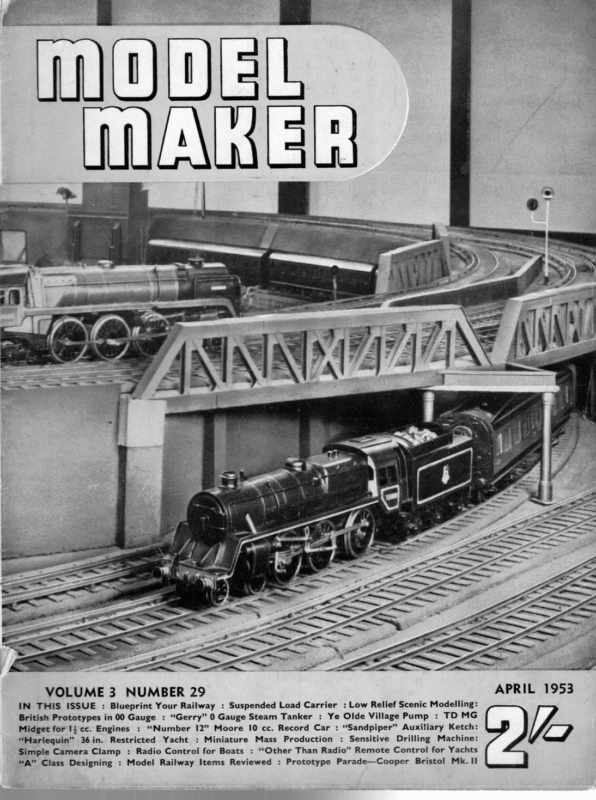
SHEET | OF 2. 7 : a SANDPIPER — : SEMI-SCALE AUXILIARY ENGINED – ; : y : : , , CLARENDON RD. HULL CONSTRUCTION 14 DIA TAPERED OF MAST 1/7″ MODEL MAKER PLANS SERVICE 38 6 D/A. DOWEL ACTUAL LENGTH OF, MAST ta DESIGNED BY COPYRIGHT a WATFORD. V4 DIA. TAPERED HERTS. ” JN6_DIA: Mi TAPERED L.O.A. 24″ BEAM 614” TRACE FULL SIZE SA/L PATTERNS FROM PLAN HULL SECTIONS DECK LASH SAILS TO MAST VIZ RAIL KEELPLATE —TM| || / : ie ° a anne “AGS WHN Pq] a aea ; os, s ; | 9″BOOM | + T / € SE 4 ; T / | | 3 Erte a rag KEELPLATE la’ply ———~ OCKPIT l 3 aa eee 166 10 ‘Y8’RUDDER COAMING STRIPS TWO OFF oe ee ” f 9 ~~ SEBS ex – COCKPIT FLOOR KBONT aes ] Q 1 4 To nS S fame ak) COAMING ii ; SIDES TWO OFF este tos 8 eas eth ; 7 ; f WS: | CABIN BACK | 6 | ! ! COCKPIT 9444″BOOM =) 5 : YP! Piz (a ae: dees : \ || X ! dhe! RAIL CABIN FRONT \ T : 742 BOOM J DECK Se coi | CABIN | ‘ =) 2 | — 7 | | I l x 0} = Wi : ——— HOLLOMAN ti Lage a|___KEELPLATE A SEE SEPARATE SHEET FOR KEELPLATE DETAILS } ! Pjo =I 7 a \ 0 ptawKs BALLAST —TM| PLANK 3 _! cme ie ~ . ‘ LU COCKPIT BACK RES
April 1 953 ANOTHER SIMPLE SEMI-SCALE BOAT gs Pe : AUXILIARY ENGINED KETCH BY A. M. COLBRIDGE Sardviver is a semi-scale auxiliary—a model pleasing and realistic in appearance which can be operated under sail or by means of a small electric motor driving a screw. The type of construction used is somewhat unusual, but saves working time and gives an accurate assembly with the minimum of trouble. The description is confined to making a “ basic” model. You can, if you wish, add a host of “full-size” detail to your finished craft—or stick to the straightforward design given and get your replica of Sandpiper in the water after about a week of evening work. Furl or remove the sails and let her cruise slowly under the auxiliary motor, or set the sails and switch off the motor and watch her speed across the local pond in a smart breeze. Good stability in rough water is accompanied by a fine turn of speed. Then on windless days you can get the laugh over your fellow-yachtsmen by switching over to the motor. The hull is built about a vertical keelplate which extends the full depth of the vessel. The keelplate is cut from 4+in. waterproof ply and the hull itself is in the form of two carved wooden shells glued to either side of this keelplate. Cockpit and engine room floor are mounted across the central keelplate and the top of the keelplate also acts as a centre support for the din. thick deck, so no deck beams are required. Choice of wood must be left very much to the builder. For a small boat like this so little is required that odd second-hand planks may be obtained from the woodyard, too small for anything else but very welcome to model boat builders. We were lucky enough to get four pieces of sugar pine (Planks | and 3 cut out of the same plank)—and all we paid was 4s. 11d. plus a tip to the yard man to plane it up to size. Start by cutting out the keelplate to the exact pattern shown on the second drawing, including all the cut-outs. No further work is done on the keelplate until the two hull shells are carved. Each shell is carved from three planks. Follow the hull construction sketches on the main plan. Planks 1, 2 and 3 are glued to each side of the keelplate—the planks glued strongly and permanently together, but plank 1 only tack-glued to the keelplate. The assembly is then carved to the finished outside hull shape. the two halves separated from the keelplate and hollowed out before glueing back on the keelplate permanently. A lot of time can be saved by marking out the plan shape and cutting the side elevation, shape each plank before glueing up, sandwich fashion. These shapes are clearly indicated on the main drawing. When the three planks have been cut to side elevation shape, lay plank 2 on plank 1 and mark its position in pencil. If plank 1 is now cut out allowing 4 in. overlap for plank 2 to be glued in place, this will remove a considerable amount of wood which would otherwise have to be carved away. Similarly, mark the position of plank 3 on plank 2 and cut plank 2 away (allowing the same 4 in. overlap). Then glue all three planks together strongly and repeat for the second side. Assemble the two sides on the keelplate, tackglueing in place and, after allowing sufficient
MODEL MAKER time for the glue to set, carve to outside shape. Sand and finish smooth. The two sides can then be removed again carefully and carved right out, leaving the walls about 4in. thick, with slightly thicker “ flanges ” where the sides glue back on the keelplate and where the deck is subsequently glued down. Before glueing back the carved and hollowed sides the keelplate assembly must be finished. First mark out and cut the deck from 4 in. thick material. Note that there are two cut-outs to be made in this deck. The cockpit cut-out is pinned and glued in place across the keelplate and gussets added to brace. An engine room floor is also pinned and glued across the keelplate. The mast slots are faced each side with plates of 1/16in. ply, glued and screwed in place. The stern tube carrying the propeller shaft is a length of brass tubing fitted into a 4 in. groove cut in the keelplate and secured with metal straps. The thrust line is very slightly offset with regard to the true centreline, using this method of assembly, but this does not matter. The electric motor can now be mounted and the propeller shaft installed and coupled up. Make a battery box to fit just in front of the motor and complete the necessary wiring. The cockpit front (cut from 4in. material) can be secured to the keelplate and cockpit floor and a switch mounted in the cockpit to control the motor. Check that the motor unit is operating satisfactorily, drill a hole through the keelplate for the rudder tube and then glue the two hull shells permanently in place. These must set thoroughly before the deck is added. After the deck has been glued and pinned in place, the cockpit can be completed, making ballast weight is plumbers’ solder which can be filed to shape and then bolted in place. The deck cut-out in the centre of the cabin gives access to the engine room for changing batteries, etc. The cabin top is detach able (the top being jin. thick and rounded) and is fitted with a cork “ plug” which should be a close fit in the cabin. The portholes cut in the cabin sides and front should be “ glazed ” by cementing thin sheet celluloid over them from the inside so that no water can get in and possibly flood the hull. The masts are tapered from 1 in. dia. dowelling. These plug into the slots in the keelpl ate and are steadied by single stays. The booms can also be tapered from dowelling, or cut from rectangular strip. Conventional goosenecks and similar fittings are employed. Full-size paper patterns of the sails should be prepared from the main drawing, cut from any suitable material and hemmed. Dark red sails will look particularly nice on the finishe d model, as a change from white. The method of rigging is up to the individual builder. The foresail sheet should terminate ona horse. The other sheet lines can terminate at screw eyes secured to the deck. An auto- matic rudder is highly desirable and can be rigged to the tiller arm with a little ingenuity. The tiller arm is then spring-loaded to stop: in the central position with no pull on the sheetline by means of a rubber band. Alternatively, lash the tiller between two screw-eyes or cleats secured in the cockpit coaming and adjust the fixed setting as required. It is an advantage if the bowsprit is mounted in a fitting allowing it to be knocked back in a collision. Rubber bands then normally tension the bowsprit forwards, providing a shockabsorbing action. A fixed bowsprit is more liable to get broken. If this is one of the first model yachts which sure that it is watertight, and the cabin sides added. Round each side of the hull, and flush with the deck-line, is glued and pinned a 4 in. x ¢ in. rail. If this strip is steamed or wetted it can be bent easily to the required curve. The rudder assembly can now be fitted and the hull sanded down again all over and painted. The amount of ballast required will depend on the type of wood you use for the hull planks and the amount of hollowing out, as well as the weight of the auxiliary motor installation. You can determine the amount required by floating the model in a bath of water, without sails or masts, and see how much weight is required to submerge the hull to a waterline parallel with the design load waterline, but about }in. lower. A very convenient form of you have constructed, build the Sandpiper simple, following the plan, and keep the rigging simple, also. If you are more experienced, add any other little details you may have learnt from experience make for better sailing but, remember, this is essentially a semi-scale model and we do not want too much obviously “model” gear cluttering up the deck. Make it look like a real boat, in other words, even if it is only a 2 ft. model. If you want a sailing craft with performance as the main aim, ‘build a definite racing design—not this little auxiliary, which is intended solely for pleasure sailing. FULLSIZE WORKING DRAWINGS ON TWO SHEETS TO MAKE A MODEL WITH HULL OF 24 ins.OVERALL LENGTH AND BEAM OF 6¢ins, AVAILABLE FROM MODEL MAKER PLANS SERVICE, 38 CLARENDON ROAD, WATFORD. 216 PRICE 4/6 POST FREE
April 1953 Glueing the Layers 6 bei best glue for “ bread and butter ” hulls is undoubtedly one of the two solution synthetic resin glues. The one I recommend is Aerolite 306F with its Hardener GBM and _ arrangements have been made for this to be supplied by The Precision Model Engineering BERNARD REEVE COMPLETES HIS DESCRIPTION OF CARVING THE HULL. MODEL MAKER IS HAVING “HARLEQUIN” BUILT FOR RACING THIS SEASON BY WELL Co., KNOWN whose PROFESSIONAL address is A. LEVISON given earlier HARLEQUIN 36 IN. REST. YACHT in this article. The method of using is to apply the resin to one surface and the catylist or hardener to the other by means of a wooden spatula, using a separate one for each solution. Do not be too generous with the spread as this is a gap filling glue and will fill up to a 1/20 of an inch, so spread thinly and clamp for 2-3 hours. Glueing Clamps . The most suitable clamp for layer hulls is a home-made one and Fig. 4 gives details of the type I have used for years with conspicuous success. Four are needed and the battens should be 4in. x 14in oak or other hardwood with 2 BA or } threaded studding with a nut and washer on the bottom and wing nuts and ‘washers on the top batten. By drilling a series of holes at 4in. intervals from the centre line you can accommodate varying plank widths. Order of Glueing The first two planks to be glued up are H and G followed by F. When glueing F to the other two, packing pieces must be arranged to ensure the pressure will be concentrated on the right place. If pressure were to be placed on H it would be likely to distort the plank and a bad joint would result. Other planks can now be glued together in pairs and these pairs added to the pack; plank S being the last to be added. Before glueing up the keel pieces the position of the keel bolts must be drawn on the side of each piece and each one drilled for 10-gauge motor-cycle spokes which will be used to clamp the lead to the keel appendage. If you possess a bench drill use it, if not drill half way through from the top and meet from the bottom as it is imperative that these bolt holes be absolutely (Above) The completed hull as built by A. Levison. Note this is vertical bread and butter layers, which enables some saving in wood to be made. On the right: A conventional horizontal layer hull in the home-made clamps described by the author ——L———— vertical otherwise the keel will list to one side or the other, which would ruin any chances of the model sailing a true course. . Obtain the keel bolts and use these to clamp the keel pieces together while you carve them to shape, but do not attempt to carve the top face of plank I yet, wait until the whole pack is glued together for general carving so that the two sections will blend. Carving the Outside The blocks must be firmly fixed upside down to leave both hands free for carving. To do this take two pieces of 2in.x1in. an inch or so wider than the hull. Screw these across the hull from the gunwale to gunwale on sections 3 and 7 then upend the hull and screw these battens to the bench top. Few tools are required for carving. I use a 6in. block plane, a 1 in. paring chisel. The lin. chisel is used to rough out the outside,
ieee cia MODEL MAKER followed by the plane with its iron razor-sharp and set fine. This initial shaping will get the hull down to within 1/32in. of the finished size. The final shaping is done with garnet paper; I use this class of abrasive as it is “ opencoated” and does not clog with wood dust. This sanding is done rapidly by means of my friend the Wolff Cub Drill which saves an enormous amount of hard work. _ To ensure a symmetrical hull, a set of card templates must be prepared from the body plan sections and these offered to the hull at the appropriate sections as the shaping proceeds. Carving the Inside Drill the bolt holes in layer H and use these to accommodate two long screws which are screwed into the bench top, supporting the fore and after ends of the hull on well-padded supports. See that the hull cannot rock side- ways Or you may split layer H. Before start- ing on the inside, the sheer line must be cut. Using the L.W.L. as a datum, mark the line of sheer from the profile, deducting the thickness of the deck, otherwise the model will come outside the 11 in. rating depth. When the sheer has been cut, wrap a piece of abrasive paper around a 12 in. piece of 2in.x1in. and using from stem to stern rub down both sides at once to the scribed line. A couple of outside-ground gouges, one with a flat sweep and the other more rounded are the tools to use and these must be razor-sharp and kept so as obechi does not take kindly to blunt tools. Take cuts in a diagonal direction and watch out for your Vee guide grooves. Care is needed as you approach the limit thickness when the gouges are discarded in favour of coarse abrasive paper. Here again the Wolff Sanding Outfit is a godsend; if you must do the job by hand use the paper on a cork block. I used sections of a cork table mat iin. thick which I purchased from Woolworths before I purchased my Wolff as this thickness gives to either convex or concave surfaces. Remove the finished hull from the bench and in good daylight view it from all angles, when any bumps or hollows will be apparent, remedy any such defects and glue on the assembled keel appendage unit, making quite certain that it is truly vertical. At this point check the weight of the hull, which should come out at 1 lb. 12 oz. The next step is to carve the skeg to shape and glue it to the hull. It is as well to leave the top of the skeg flat and carve a flat on the underside of the hull rather than attempt to hollow the top face to fit the hull. Glue and a pair of 3in. by No. 2 brass screws will hold it securely; omitting the screws and relying upon the rudder tube for extra support may result in distortion of the tube if the skeg is accidentally knocked. Again make absolutely certain that the skeg is lined up dead true with the keel appendage otherwise the model will never sail a true course. as Lastly, drill the hull and fit the rudder tube shown in Fig. 6 which gives sufficient detail and’ makes a lengthy description superfluous. The whole of the inside must now receive three coats of the best yacht varnish. I use International Paints Ltd. E.309 Varnish, a 3 pint tin costs 4/-, and their address is Grosvenor Gardens House, London, S.W.1. Dilute the first coat with 20 per cent. turpentine and use the other two neat. The Lead Keel Personally I think it pays to get this cast. Mark off the lead line from the profile plan and cut to the line with a fine saw, carefully facing the saw surfaces with abrasive paper. Before taking the pattern you have cut off to the foundry, polish it well with fine abrasive paper and give several coats of shellac and polish with a rubber soaked in shellac as in french polishing. Also let the foundry have pieces of 10-gauge spoke and arrange for them to core the bolt holes to save you the very real trouble of drilling the lead afterwards. While you are awaiting the lead keel the deck beams should be made and fitted to the hull by means of halved joints. The rise of camber of these beams is measured from the profile and the top surface of each beam planed down to conform to the curve of the camber. The position of these beams and longitudinals or carlins are shown on the deck plan. Note that the rudder tube butts against the aftermost beam to which it is attached by means of a U shaped bracket. Having collected the lead keel, weigh it to Se that it agrees with the designed weight; if over, drill in. holes on the top face to bring it within the prescribed limit and fill these holes with paraffin wax (candle grease). All being well, bolt the keel temporarily in place and complete model, adding weight at the mast step position to agree with the designed weight of spars and sails plus weight for other items, deck, etc., as shown on the table of weights, and weigh the complete hull unit. This must come out at just under 12 Ib. and if over, the total hull weight must be reduced accordingly, other-
April 1953 wise the model will be out of rating and not of the deck of }in. wood whose outside edge accepted for class registration. matches the outer deck line and use a draughtsman’s ruling pen and waterproof indian ink. When all is in order the keel must be fitted permanently. Get your cycle dealer to run a Start with the outer line and slide the template back towards the centre line } in. for each line, repeat for the other half. The deck can now be cut to shape, and }in. ply reinforcement pieces glued underneath where hatch, mast-slide and deck fittings come. Cut out for hatch, mast-slide and drill for rudder tube. Fix deck to gunwale, having coated the gunwale tops with white lead, and screw down, using ?in. No. 2 brass screws every two inches. Fit mahogany stem and stern pieces, hatch coamings and deck coamings by means of jin. brass pins. Finally, give the whole a couple of coats of E.309 varnish. 1 in. length of thread down the spoke ends and turn the lower ends over to form an L hook. Coat the top face liberally with white lead, grease the spoke well with tallow, not motor and insert, punching the hooks well grease, into the lead. On the inner end thread a largediameter washer, then a piece of leather or plastic strap to form a carrying handle, another washer and finally the original spoke nipples reversed, i.e. large head downwards. Before fitting the deck, if 1/16in. resin bonded ply, it should be plank ruled. A centre portion $ in. wide is stained mahogany, this is the king plank. Now give the deck a coat of white lead undercoating, rub down and give a coat of ivory enamel. The deck is now ready for ruling. It will be seen from the deck plan that the plank lines follow the outside curve of the deck. The quickest and most accurate way to do this is to make a template half the width The effect of varnish on the lined white deck is most pleasing. Lastly, polish the hull until it is as smooth as satin with flour abrasive paper to prepare it for painting and the fitting of the rudder which will be described in my next article. FULL SIZE WORKING DRAWINGS OF “HARLEQUIN” ON TWO SHEETS, GIVING DETAILS OF SAILS (THREE SUITS), MASTS, SPARS, BRAINE GEAR IN ADDITION TO HULL LINES AVAILABLE FROM MODEL MAKER PLANS SERVICE, 38 CLARENDON ROAD, WATFORD. PRICE 9/6 POST FREE. _— — MR. TUCKER WRITES . . . . M Class Design “Sunkiss” Sir, The M-class is an International Class, origi- or shifting ballast definitely is prohibited. To fit this rig is, therefore, equivalent to the use of shifting ballast. Undoubtedly, it is the designer’s job to exploit any weakness in a rating rule, but to me in this particular case, the letter rather than the spirit of the rule seems to have been observed. Here is one last thought about the matter. Subject to limitations imposed by their relative sizes, the model is supposed to resemble the nated in the States, and as such any change in rule is subject to international agreement. The American designer of this model has cleverly exploited a loophole in the rule by fitting her with a sliding rig, but whether this is desirable or not is a matter of opinion. This contrivance makes it possible to get a reasonably good performance with an unbalanced hull, and also makes matters very much easier for the inexpert skipper. In use this device has two effects. It alters the effective Centre of Effort of the sail-plan, and also the yacht’s fore-and-aft trim. Now the rig of a model of this class weighs prototype nearly as possible. Can one mast some feet forward as they round the buoy for the run home? Yet if one abandons all pretence of following the prototype, the model yacht becomes merely a toy for grown-up children to amuse themselves with. approximately 1 1b., and since the sliding rig, as exemplified by that of Sunkiss, is mounted Yours faithfully, H. B. Tucker. on a sliding base bar, which must weigh 4/6 oz., (We welcome Mr. Tucker’s views on the subject— and are happy to have tempted this famous designer the total weight involved must be the best part of 131b. As the range of motion provided is 7 inches, it is obvious that its movement must considerably alter the yacht’s fore-and-aft trim. The use of a sliding rig is not specifically prohibited by the rule, but the use of movable ESS ee as imagine the crew of a racing yacht shifting the into print. We are happy to announce that Mr. Tucker has already provided us with a new 10-Rater design “Io-II” which will be appearing shortly together with a long two-part article on designing for speed and the points considered in producing this particular yacht—The Editors.) 219 eS
O1dva Yoda 027 69194} opeyPrey, PsOueyYINOW«¢ O”qsoo9IJWi]MsmyOpI0bYe[TedY‘Eamr]S1.uoqofuTsA[Un)DNe}MvpstIy[By]e}KRjaIoOOwrPpAJYsSseS}nrPigpuU,[To3“WjN]oAsIyMlaAtSTyYIveOOjJqJqUNO!oGALda19[Ws[BS}igSeUQIIveTpME‘mApaJToJOeuRO0uly}USIoDJ9N2YYOUqSSI aYjuey2TMo}L4e]sSulIrIq)xnJ‘p1OAos9Uu}yeW0e[rJ}3]IajMAiodOouUvfJn9}ugIMsStapA“r[UveePM1ni0oojy‘w3Y]pIfdOSSrsaaMqul[heooPevExyupl sSy0o9‘S1oI}ju[i8Y}oT)Tne,BgmAp]0uRJOaJdYNUo)yqOrosMm‘[lA9dLngos[4EuBIUSSsMI“TJi)JIoNYOyrapOqfsAIde1yQINUoseeu9mq}u‘’s]}Il“rgNYAUI“iyoWBOOpo‘,SlgIon0NeB)aqwTqud’eW1O9yYsTSre


