- Witchcraft, 1954 Model Maker Trophy Winner Marblehead. By. B.H. Priest.
- Tucker’s Topical Talks: Thoughts on Radio Control. By H.B. Tucker

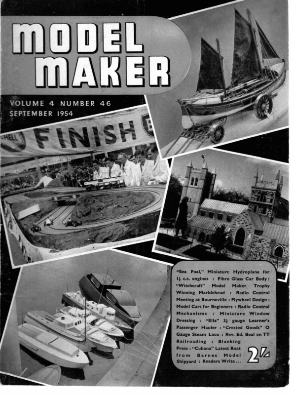
VOLUME 4 SEPTEMBER NUMBER 46 1954 “Sea Foal,” Miniaturc I} c.c. engines : “Witchcraft” Model Winning Hydroplane for Fibre Glass Car Body: Marblehead Maker : Radio Trophy Control Meeting at Bourneville : Flywheel Design : Model Cars for Beginners : Radio Control Mechanisms Dressing : Passenger : Miniature “Ella” Hauler 34 gauge : “Crested Window Learner’s Goods” O Gauge Steam Loco : Rev. Ed. Beal on TT Railroading : Blanking Press : ‘‘Cubana” Latest Boat from Barnes Model Shipyard : Readers Write… iZ [A
Presenting one of the very finest examples of Marinecraft Kits. of good working that will reward the builder with A model worthy utstanding performance. The jONA MODEL OVERALL RACING LENGTH YACHT 24-in. BEAM 5i-in. A most attractive model yacht which will delight you with its performance. The design is based on the bread-and-butter method, featuring all balsa construction, and in view of the moderate size and easy lines, it is ideal for the beginner to build and sail. Complete kit, with detailed plan, step by step instructions, cut to shape parts, tapered mast, finished sails, rigging, moulded lead keel, cement, b il, ish, PRICE (including P. Tox) : ROADS The FIONA RACING MODEL Grace Speed and LENGTH in OVERALL 3¢-in. YACHT every line BEAM 9-in. Another magnificent racing yacht which will satisfy the demands of all who are seeking a really professional model. With her light construction, perfect lines, and tall efficient sail plan, develops a speed which cannot be equalle d by any model of similiar length. A most comprehensive kit with fully illustrated plan and instructions, cut to shape parts, tapered mast (brass cross-trees), a beautif ul set of sails, all rigging, Braine type steeri ng gear, complete rudder unit, finely moulded lead keel, cement, b il, ish, 5 PRICE (including P. Tox = Me Ask your model shop for our Do AL coloured The IONA brochure featuring all Marinecraft kits or send 4d. in stamps to : 141 KINDLY MENTION “MODEL STRATFORD MAKER” ROAD. “WHEN REPLYING TO BIRMINGHAM lI ADVERTISEMENTS
MODEL MAKER) itehcraft 1954 MODEL MAKER TROPHY WINNER MARBLEHEAD BY B. H. PRIEST, M.I.MAR.E. MAY more able pens than that of the writer have written on the Marblehead 50 – 800 Rule and thus no useful purpose would be served if we once again examined the fundaments of the Rule in detail. This rule is what it states—SO inches length overall and 800 square two figures plus one or on garboards, etc., are worry about. Design is inches of sail. These two minor restrictions all the designer need not quite so simple as may at first appear, though, since the designer is given his L.O.A. and Sail Area and is free to select whatever L.W.L. Beam, Draft, and Displacement and Rig he wishes. As can be understood, this gives a great number of unknown variables to play with. Let us select one at a time and fix on a L.W.L. for a start. “Easy”, says the young designer, “I know the L.W.L. is one of the main speed factors and that the longer the better. Let’s make it 50 inches”. Alas, Mr. Tucker explained only too well in a recent MopeL Maker just why this is an incorrect assumption. Examine the 50-800 =: ha = wise 8 7 =.3) cis) aS T BE LN Set ne ? S 3 ; a j wy . | U WS F aan Sikce 7 Ame _ oan artieBtwnWO esta ine eam 108″ = ers ces .eo Le : — ACER truss OGP SECTIONS SRACED ATTRLMES | 0 . ; Ue nonin OTE. – por acowent tor coco 22 uss Out OF TOP Root ABOVE € © w MecESGamy a me Ee ge SES bi SS es Zen 2 OC : onartir as ‘a of the overcome it by fitting sliding rigs with some WITCHCRAFT MODEL MAKER PLANS SERVICE action majority of Marbleheads in a breeze. Note how many are unbalanced and how many drive their noses down when running. Take this a stage further and unless the spinnaker is reduced to minute dimensions the nose drives right under and causes the usual broach. The reason is the lack of reserve buoyancy usually given by the forward overhang in the A Class and 10 Rater boats, coupled with a degree of unbalance. Balancing a Marblehead is no easy matter. In drawing out a normal set of lines to the scale it will be noted that the shoulders are rather weak and the quarters rather too full for balance. Our American friends with their knowledge of their own rule have understood this and have endeavoured to pubes ee eT rte <— —— 520
seven inches total travel, so that the rig can compensate the unbalance of the hull by being capable of being sited in the correct position over the hull for any wind strength, and when running can be taken fully aft to prevent the nose driving under. Four people in England, it appears, have also understood this and have endeavoured to design a balanced hull to eliminate the need for a sliding rig and also endeavoured to overcome the driving under effect. They are Tucker, Lewis, Norsworthy and the writer. Tucker has had great success with his efforts by which he has designed a very rounded bow which can be seen in his well-known line of Ducks. By this means he couples balance with a long bearing length when heeled. Norsworthy and Lewis tackle the problem by a normal bow with a reverse curve below deck level, making a blunted deck plan. The Norsworthy plans are also very successful in practice. It allows fine waterlines forward but its one fault lies in the fact that the quarters have to be well fined down aft to retain hull balance. Couple this with a fine bow and we get a short bearing length when heeled. The. published design endeavours to overcome the problem rather in the manner of the International fourteen foot dinghy, by the use of very sharply splayed out sections at the bow running into a sharp tumblehome amidships which is carried out to the transom. This is done to assist hull balance and also to gain reserve buoyancy forward yet cutting it down as much as possible aft in an effort to allow the bow to lift when running. The next dimension to be selected is the displacement and here the designer must decide if he wishes to produce a light weather boat, a moderate weather boat or a hard weather. Experience with the rule has shown us that these three types fall in the following displacement ranges. Light 171b. to 201b., moderate 20 Ib. to 23 lb., and heavy 23 Ib. to 26 lb. It would seem logic to select a moderate weather boat because in this country | these conditions prevail more than the other two. And, also, the moderate boat is fairly good in light and heavy condi- se tions, whilst the light is fairly good in moderate but poor in heavy conditions, and the heavy boat fairly good in moderate but poor in light airs. For hese reasons a displacement of 22 lb. 521 Illustration shows Eros, sister ship to Witchcraft, taken on the occasion of her almost maiden appearance when she won the 1954 MODEL MAKER Trophy in the hands of Mr. Jack Lace, who hes only been sailing since 1950, on behalf of her builder, Mr. J. T. Manley, who for health reasons was unable to play his full part as mate Fj f / has been selected. On the normal mid-section in the design this gives a L.W.L. beam of 10.6 inches. A draft of 11 inches has been selected as a deep short fin is more effective, area for area, than a long shallow one. Thus we are able to cut down wetted surface by a short deep keel and at the same time keep the lead low down. This is the reason for the Seal Flipper type of keel shown on the design. The remaining point of interest in, the hull is the forward raking rudder. In the design and position of the skeg and rudder, the writer feels he must disagree with Mr. Tucker’s reasoning. For maximum sensitive control the further aft the rudder is placed the better. We are all inclined to overlook the power required by a vane to move the rudder especially when running fast. Tow a boat at a walking pace and endeavour to move the tiller arm and one is amazed at how hard it is to move. Hence the more power we can give the vane the better. To gain the above two points the forward raked rudder is used. Firstly it puts
MODE MAKER) the rudder right aft but leaves us the required 3 in. rotational centres between vane pintle and rudder stock. Secondly, the rudder raked forwards has a certain amount of flotation of its own and is thus easier to operate. Mr. Tucker’s reasons for moving the whole skeg and rudder forward do not seem sound. It is well known that when converting a Braine- in our case. What we like. In light weather too much length cannot be given to luff and leach or the light wind will be unable to open up the spinnaker. The designed top spinnaker is 56 in. luff and leach and 33 in. round the foot. This spinnaker is also used in moderate breezes steered boat to vane, the skeg and rudder must upwards with the lower aspect ratio top suit. be moved aft. In all the writer’s 10 Rater designs the rudder is placed .5 in. forward of the L.W.L. ending and all these boats carry their maximum-sized spinnakers even in a fourth suit gale, which would seem to prove the steering effective. | With the published design the distance of centres should be 3 in. as already stated and the distance from vane pintle to vane tiller pin 1 in. It must be stressed that “Witchcraft” was not designed for the novice. She was designed for the top class racing skipper who demands a boat he can drive hard. She was not designed for beauty but for effect and because of all this two complete top suit rigs are required. Here the strength of wind will allow the spinnaker to fill and keep full. Small spinnakers are shown as even this ship can be driven under, but in her case no broach happen s as she just races on with the deck comple tely submerged from end to end and under these conditions one travels faster on top of the water if a smaller spinnaker is used. Finally the proof of the pudding. Two boats only have been built to the design and both won the first race they were entered for before being tuned up. Their owners are deligh ted and I feel the design will give satisfaction to any who build her. P.S.—Word has just been received that the Morecambe boat has just won the Sandilands Open Marblehead Trophy, skippered by her For light to medium weather a 4 to 1 ratio mainsail is designed, the whole rig being lifted well clear of the deck. Apart from this and providing we use a IS in. spinnaker pole we can put up Spinnakers owner are unmeasured in the class but the hoist must Tom Bradburn, after a sail off with Floriana, the 1952 British Champion, skippe red be at fore-triangle height which is limited to 80 per cent. of the height of rig or 56.5 in. by Walter Jones. So the record for the design now stands at three starts, three firsts. i FLYWHEEL DESIGN (continued from page 519) As a working example, assume that we have constant torque (Q) of 10 ounce-inches available, as before and that the flywheel, of brass, is 3 inches in diameter , 1 inch thick. Weight of flywheel same equation as above to calculate acceleration substituting Q, for Q, where: Qi = 7 (3/2)2x 1.307 pounds =2.42 Ib. Hence time to accelerate up to 12,000 r.p.m. is Time (seconds) In practice, however, constant torque is an approximate condition /2 —N1) 2 /'4 (Nmax — Nj) 2 where N1, Nz and Nmax are r.p.m., figures are various Parts of the curve, as defined in Fig. 2. 2.42 x (3/2)? X 12,000 Q, will be less than Q, and hence the accelera tion time will be longer, as would be expected with a falling off 450 x 10 = 14.52 seconds only as = QX1— time, torque. If the conditions are such that N, approaches available over part Nmax, a more accurate solution is given by splitting the ‘‘curved torque” section into several parallel widths, of the torque-r.p.m. curve. With increasing r.p.m. the torque figure drops away. The complete torque envelope can be considered as approximately equivalent to a parallel (constant torque) section with the latter end of the envelope bounded by a parabolic or elliptic curve. In other words, once the r.p.m. figure exceeds the “parallel” limit, torque will drop off and hence the above equation will no longer hold true. A solution can still be worked out, however, since the equation of a conic curve is a relatively simple one. We can then use the equation above to compute acceleration time over the “parallel’? or constant torque section of the full torque curve and another rather more complex equation to give acceleration times over the conic or falling off part of the torque curve. One of the easiest ways to arrive at an answer is to calculate the mid-ordinate or average torque over this portion of the torque curve and use this figure in the or applying calculus to solve the torque-t ime relation- ship. Since this is a purely mathematical study, we will not elaborate further the details involved. The working formulae given are satisfactory for arriving at an answer to most practical problems. TABLE I. Specific weights flywheel materials. Material S (pounds per cu. in.) Aluminium * Aluminium bronze Brass Bronze Copper Cast Iron Steel *“Not weight. 522 normally employed -0975 -293 -307 .308 -318 -260 -283 on account of its low specific
ModE WAI Crested Goods (Continued from page 501) a medium file, bring to shape as shown on the the tender body. Next mount the body on to the sole plate and sweat all round. Cut another piece of brass to form the dividing plate between the spirit tank and water tank and solder into place. Next set the pump in place and fix with two 10B.A. brass screws. Make a union nut to suit the pump and silversolder a din. pipe into it and screw it on to the pump, bend the pipe round so that it points drawing and you will find that when the job is completed it will look as if it has been made from one piece of metal. We will now make the coal rails, which is quite a simple job. First draw them out on a piece of wood about I2in. long x 3in. wide and using 20 gauge spring wire put a length along the top rail which you have marked; put a panel pin here and there each side of it, pull the ends round and panel pin in place. Do the same with the other rails, fitting each end so that it just touches the bent ends of the top rail. Lay the upright bits over the top of the rails and soft-solder the lot into place (do not use too much solder or it will go into blobs and spoil the look of the job). to the back of the pump (if you have not already made your pump you can fit the threaded end on the valve box so that it points towards the back of the pump but on an angle). Make a small fitting to come through the bottom of the tender and fit a 4 in. coil pipe on the underneath side making sure that this clears the wheels, and solder into place. Make a spirit control valve using a tin. brass rod turned to 3/16in. diameter at the bottom end and sweated into the bottom of the tender. Fit a 1 in. length of jin. pipe so that it points to the front end of the tender. When this has been com- pleted take the pins out and you will have the rails in a straight length. Now over a short length of gin. round stock, radius the two corners to suit the tender coping. surplus wire and then solder Cut off the into place on -— — R.C. skipper got his yacht going satisfactorily on one course than he immediately made her change direction TUCKER’S TOPICAL instead of settling down to enjoy the sailing. I sup- pose one TALKS: THOUGHTS ON _ RADIO CONTROL ge, Two recent conversations have given me much food for thought on the subiect of Radio Control for model yachts. The first was with a prominent yachtsman who is seen, amply bear this out. For no sooner had the for the novelty of short leg—with a calm belt down one side of the pond. The mate takes the good side of the lake, and we start the boat on the long leg. The vane gear is in charge until she reaches the shore when the mate puts her about. She sails off on the short leg still in charge of her vane gear, but is heading into the calm belt. When the skipper thinks she has gone as far as advisable, he brings his R.C. into action, throws the vane out of gear, and puts the boat about, and as she fills on the long leg, shuts his R.C. off and the vane resumes control. Without R.C. the As regards the latter, the skipper sails on the “feel” All demonstrations of R.C. for model yachts, I have make allowances vane when it seems desirable. For example, let us suppose we are sailing to windward—a long and a also actively interested in R.C. What apneals to him is the possibility of introducing the tactics of fullsized yacht racing into model racing. In my younger days I did quite an amount of yacht racing, both as crew and skipper, and could, therefore. see his point of view. Against this, I pointed out that the skipper of a full-sized racer has not only to manoeuvre his yacht, but also to get the utmost speed out of her. of his craft, but the skipper of a R.C. model stationed ashore at his transmitter is unfavourably placed to observe minor wind variations. which are far better dealt with by a sensitive automatic steering gear (such as the Vane gear) aboard the yacht herself. : My second conversation on this subiect was with a well-known model yachtsman. He stated that he had little interest in R.C. for model yachts because it places the emphasis on R.C. rather than on sailing. must R.C., but its practitioners remind me of early radio listeners’ “Knob Twiddling”, when enthusiasts tried to “log” a maximum number of stations, rather than listen to a specific programme for its own sake. I have nothing against R.C. so long as it does not interfere with actual sailing, but it appears to me that in its present form people, who take it up, will soon tire of mere “knob twiddling”. If R.C. can be made to act as a usefu! adjunct to sailing, then its future is assured. What does this imply? My suggestion is that primarily the yacht should be sailed on her Vane steering, but that the R.C. should be arranged so that the skipper ashore can step in and over-ride the skipper has to rely on various guying devices and has no certainty of making a tack of the exact length he wants. In other words, I suggest that R.C. enthusiasts should concentrate on the improvement of their methods. so that the plain sailing can be left to the vane gear and the R.C. thrown occasionally into action when actual manoeuvring is needed. 532


