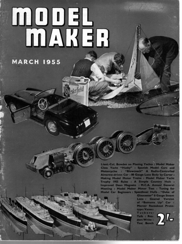
- Husky, Third of the MM Class 25-In. Yachts For The More Experienced Builder. By D.A. MacDonald.
- Model Maker Yacht Trophy 1955.
- Planing Yachts Part I. By Lt.-Col C.E. Bowden
- Addendum on Vanes. By H.E. Andrews.
- Tucker’s Topical Talks, From Wee sixes to French Babes. By H.B. tucker

ae MODEL MAKER} THIRD “HUSKY” DESIGNED BY D. A. MACDONALD ON lem. To design successfully to an existing rule, guided by the accumulated experience of many years of racing history, is difficult enough, but rating rule involves a peep into the future instead of a study of the past and present, and makes scope for a great deal of conjec- ture, particularly in the choice of proportions. The only. safe assumption one can make is that any new rule will eventually produce M. M. CLASS 25 in. THE “CIRCULAR ARC” METHOD said, however, that the large increase in hull size (accompanied in the 10-rater and A-class by a reduction in sail area) has been largely accelerated by two important developments. The first is the introduction of vane steering which enables sails to be used so as to provide greatly increased driving power. The second is the improvement both in sail-plan design and in the technique of sailmaking, which enable a restricted sail area to be used with greater effect than before. It is, therefore, possible that no further large-scale improvement in the performance of sails can be expected. If so, we may now be approaching finality in the development of yachts to existing classes. I am sure, however, that even if the methods of sail area measurement are unchanged (and these methods are a distinct hindrance to development of more efficient sails), we can expect some further progress, and plan for still larger hulls, with 10-raters and A-class yachts based on L.W.L. measurements rating rule can be quite a complex prob- new THE L. 0. A. YACHTS FOR THE MORE EXPERIENCED BUILDER. [DESIGNING a boat to a new and untried a OF boats which are bigger (in at least some respects) than the originators of the rule ever visualised. For example, A-class yachts now being planned and built have displacement figures approaching twice those of yachts built when the rule was first introduced. The tendency to increased weight is even more marked in the 10-rater class, and in the M-class, the typical displacement has increased by nearly 50 per cent. in the few years of its life. It must be FULL SIZE DRAWING AVAILABLE FROM MODEL MAKER PLANS SERVICE, 38 CLARENDON ROAD, WATFORD, PRICE 4/6 POST FREE We have taken the liberty of adding one or two explanatory details to Mr. MacDonald’s lines, since we feel that this boat offers an excellent opportunity of indicating part of the technique of building direct from a naval architect’s drawing to modellers hitherto completely baffled! | HUSKY 5 MM. CLASS YACHT ara wht ‘ My) D.A. MACDONALD ie) WODEL MAKER PLANS SERVICE wi 38, CLARENDON RD WATFORD. HERTS. 4 x SESE 5 : ‘a ae al 5 5 Pia (irr Wh 2 Bs NPS 8, Ni s E re) |raee CZ, | ig ! , wun bel ese rene ig ws ae ae e Fr: Fane wessui | we | . AN es AN i \ RaNS Ties [eee Nt ine a tae SF abe Mio. : ZZ L = – \ =. Sane Boe Dg a rye A ; ——3 = rcs wate — Bm on Se) —— 7 — ie ~“ ts ” oF AEN i tos coon a las 100° te 4 te] te SKETCH SHOWING HULL THICKNESSAND KEEL ATTACHMENT_ Se gh Me ete Ar cece FOR THE LESS res EXPERIENCED ww SUILDER tan ; Tas 142
MARCH around 60 inches, and the M.-class displacement up to the 25 Ib. mark. When the M.M. Class first saw the light of day, in December 1954 MopeEL MAKER, my first reaction was to consider the idea as a challenge to the designers, so I set to work on a study of the problem. My first conclusions were contained in a letter to the Editor, published in the January 1955 issue. Since then | have been given the benefit of Vic Smeed’s experience in the construction of two boats to this class, and his figures show that a higher proportion of the total weight can be carried as ballast than I had estimated from experience of the larger classes, particularly when constructional methods specially adapted to small models are employed. As a result of this interchange of information, the proportions for Husky were decided upon, and provide for the amount of ballast stipulated in my original calculations, but a reduced over-all weight. This is a boat for the experienced builder Iversen or Wampum types, with simple stops for setting the vane angle for beating, could be made very easily, and would be extremely light and robust. Readers who have seen yachts designed on Guy Blogg’s “torpedo” principle (e.g. the successful A-class Samoena) will be interested to note that some use has been made of the system in the design of Husky. The sections are based on concentric circles, but only between the planes enclosing the 20-degree “In” and “Out” wedges, the necessary slight deviations from the circular form in this region being balanced fore-and-aft. By this means, it has been possible to obtain the desired mid-section rake, and also the desired form for the underwater lines with very accurate volumetric balance. (There is no movement of the C.B. at 20 degrees heel.) _ In conclusion, I hope that Husky will be of interest not only to model yacht enthusiasts, but also to the many readers who produce the small power boat models illustrated in these pages from time to time. Their skill and techniques can be well adapted to the construction of a yacht of this size, at beautifully a very built moderate cost, and the finished craft should provide considerable pleasure in sailing. i M.Y.A. CHAMPIONSHIPS 1955 DATE would like to add just two points. One concerns the mast and the other concerns sails. | suggest that the rather tall mast of Husky be made of jin. O/D aluminium tube, a suitable wall thickness being 26 S.W.G. Some inexpensive lightweight television aerials (e.g. indoor types) employ tube very suitable for this purpose, and if the tube is not otherwise available, an aerial can be “cannibalised” to produce masts at a fairly moderate cost. The aluminium tube should extend up to the jib stay, from which point the mast continues as a | VENUE | May 28, 29,30 …| Birkenhead | July 16/17… … | Poole September 24/25 … August 7/13 … eptember I0/II | EVENT 10-Rater -. | Fleetwood … | A-Class and Race … | | for Y.M. Cup — | 36in. Rest. Class Hove oe | Marblehead Fleetwood … | 6-Metre ionship, and other events. It proves thot in certain circumstances of hard breezes, the planing type of model had similar characteristics to full-s’z2 design in the same feld. This was a yery worthy thing in itself. H The builder has told me 150 be that he had little experience of model racing at that time with this entirely novel venture , which he kindly Says was prompted by some of my writings encouragIng experiment. I am delighted to hear that Mr. Waddington is now building a Triplan e II along the lines of Uffa Fox’s Flying Twenty-five. It is just these sort of enterprising experiments that yachting full of interest and progress. experiments will go further and make model [ hope such not stop at scaling- down the Flying Series. “Triplane” undoubtedly shook some of the more conventional model designers out of their well-worn ruts, particularly as the hull was what is termed an “unbalanced” one. The truly “balanced” hull was once looked upon as the only type with a hope of winning a champio nship. However, it has been d’scovered in tank tests and full- size practice that a slight weatherhelm, or tendency to run up into wind, will provide a hull with less resist- ance, and windward. Provided lower this counteracting leeway losses, tendency offset of is when not rudder great, creates beating the an to slight “aero- dynamic flap” or “arching exect” of the hydrofoi l kee| appendage, with an increased pull to windward in the water. Particularly is this so when the rudder is attached to the trailing edge of the keel as on many full-sized vachts and on some modern “A” Class models. Full-size racing helmsmen know thie threuch practical experience, but proof has confirmed their experience by the American Stevens Inctitute Tank tests and elsewhere. One of the big advantages of the Vane Steering Gear, and the reason for its superseding the Braine gear, has been the ability to adjust a model yacht with a slight weatherhelm for windward work, and then to adjust the Vane gear to sail the model off with a little opposite helm. The full-
MARCH, size “X” One design keel boat Class in which I race, and have the honour to be Captain of the Parkstone Division, has slightly “unbalanced” huli lines with this desirable tendency to slight weatherhelm, and our boats have always been noted for their excellent It may windward work and great seaworthiness. perhaps be necessary to warn some that an excessive tendency to run up into the wind is fatal, and causes a hard mouthed tiller that creates excessive drag. This was explained by the Stevens Institute findings which were:— (1) A yacht going to windward has the least resistance to forward motion when the helm angle has one to three degrees from the centre line, resistance increases with a change of helm of the Uffa Fox Flying Series which Mr. Tucker has always deplored in no uncertain terms. I sail this model across the open seawater of Poole Harbour steered by Vane Gear, and find her close winaed, and capable of short planing in a good breeze. It must be recognised that all design is a compromise, and that these special planing keel craft requi.e a stiff breeze to show up well when they wa-k away from the convent.onal non-planing displacement craft. The latter have the edge on them in ‘light weather, and in exceedingly heavy seas. Fig. 1 shows the planing type bottom and transom of the type, and also the special keel, which appears somewhat foreshortened in the photograph. Fig. 1. from this position either way. (2) The angle of leeway decreases with this angle its wide planing transom hull is by no means excessive. If, on the other hand, such a hull is sailed on its ear incorrectly, the centre of buoyancy shift can be avpreciable. and create excessive weatherhelm. I believe I explained in an earlier discussion that I have paced other classes in my full-size Flying Fifteen hull which I now use for experimental sail rigs, and have found it holds up to windward with the best quite satisfactorily in spite of its special planing type keel Although a reasonzbly “balanced” hull is hull. necessary, it is not essential to have both ends ex>ctly balanced. It is interes‘ing to note that Uffa Fox’s latest large “conventional” cruiser “Sandavore” 49 ft. L.O.A. and 16-25 ton displacement has lines that are not entirely “balanced” according to conventional methods. I have a scaled-down “Flying Ten” from the Fly‘ng Series. in the form of a 10-rater model yacht, built by the artist, and (full-size) yachtsman Mr. Ray Coombes. which did very well in the first model race in which he sailed in the 10-rater-class. This model has the cut away high aspect ratio swept back keel Flying Ten built The scaled-down “Flying Ten” as a 10-rater model built by Mr. Roy Coombes, and now used by the author. Note the plan ng type transom and bottom—also special hydrofoil keel. of slight weatherhelm. If the Flying Fifteen (and Series) type of hull is sailed reasonably upright when going to windward, with a low rig and other aids, the weatherhelm from 1955 the Fig. 3 at the bottom of the page shows my fibreglass Flying Fifteen type of model. This hull has somewhat modified lines, but has proved good to winduae under radio control, when sailed reasonably upright. A most versatile designer I am convinced that all yachtsmen who have come into contact with Mr. Uffa Fox will disagree with Mr. Tucker’s general appraisal of this great designer. I personally prefer the description I saw publi hed of Uffa Fox as “Expert in everything that floats and sails from canoe to cruiser”. Uffa Fox’s initial pub- licity was surely due to his outstanding exploits when sailing across the Atlantic in his youth. Alco his canoe speed record, and his sail across the English Channel, in an open racing 14 ft. dinghy, including a race the other side and immediate sail back. These and many other exploits were bound to give the young man of those days publicity. Many others have admittedly produced planing boats, but Uffa has done a deuce of a lot in leading planing design, and he certainly initiated the practical planing keel boat. He designed the most ropular of all planing dinghies in this country, the Firefly Class, and has set a Fie. 1. Below: Roy Coombes scaled-down and now one of the author’s fleet of within 10-Rater rules, experimental boats with in the second part of Fig 3 on the left: This will be dealt of a Flying Fifteen a fibreglass version this article, andiniswhich has been embodied some of the of model, author’s experiments with rotating streamline masts and his fully battened wing-sail 151
MODEL MAKER) cracking pace in his other dinghy designs. His early achievements, with over 30 firsts in the 14 ft. dinghy “Avenger” stirred up dinghy planing in no small way many years ago. J imagine Mr. Tucker is thinking of the early “skimming dishes” with the flatter but conventional hulls that- initially suggested planing keel boats. These did some fast surging and “skimming”, but not the genuine holding of a plane as we understand planing today, with a flattened speed-boat wake. Uffa Fox also gave to the yacht world his simplified rigging. Before his Fly:ng Fifteen rigging arrived, even the 14-footers had masts cluttered with an astonishing mass of wires, little cross trees and jumperstruts, with the massive drag and interference of an early biplane with inbuilt headwind. Nowadays, almost every designer produces his dinghy with a version of the Uffa Fox single crosstree swept back to a single stay on either side. It is ridiculous for Mr. Tucker to suggest that the Flying Series are not genuine planing keel boats. They are specially designed lightly loaded keel boats with a special shape and run aft to special wide planing -transoms, fitted with a high aspect ratio swept back keel suitable for the job. They operate pe ec ieee . as displacement boats when going to windward, and in light or medium airs off the wind, but when 2 stiff breeze arrives they rise to the surface off the wind and plane with a flattened wake, with a stab lity that requires none of the balancing feats of the plan ing dinghy. The Flying Twenty, and particular’y the Flying . Twenty-five are much larger planing keel boats than many people who have not seen them imagine. I remember seeing Uffa Fox sail his Flying Twenty-five at Cowes one year when all racing had been cancelled even for the Sixes, the Dragons and our weatherly “X” boa‘s. It was a thrilling spectacle as this large keel craft rose to the surfaced and planed like a fast speedboat in really rough seas and a half-gale in a cloud of spray and a flattened wake. An excellent photograph of this event has been published, taken by Beken. ft. Jollity, an old man’s dinghy, as 18 Even Uffa’s he described her, last year won the special high speed race at Cowes Regatta against all-comers. I watched this dinghy just beat the mighty catamaran Ebb and Flo, having got clear away from all the other well known planing dinghies in a considerable sea. Mr. Tucker is worried as to why Uffa Fox’s Six Metres yacht did not plane. I saw this craft being bu‘lt, and none at the yard expected her to plane, for the Six Metres rules make it virtually impossible to produce a craft that will do more than verhaps surge a little in strong winds. Most rating ru’es are produced to if they are to be considered amongst the top flight in the future. These three features are:— (1) Radio Controlled model racing yachts. (2) The planing type of keel yacht as well as the non-planing conventional “heavy” displacement type. (3) The technique of fibreglass construction, as applied to model yachts. There is much experimental and development work ahead in these three directions. Manoeuvrability Mr. Tucker indicates that he considers manoeuvre is not essential in model yacht design. This may be true in Vane steered races where the yachts sail a somewhat grooved course up and down the racing water. The great art of yacht racing, however, in the full-size field, is in manoeuvre and the tactics of racing within the rules of racing, in order to defeat the other fellow. Radio racing with two or more sailing together at the same tme arovnd a course, now offers this important feature of manoeuvre, hitherto unattainable in model racing. It will, therefore, eventually broaden and widen the whole scope of model yacht racing when it really gets going, but please Jet no reader imagine that I fail to appreciate the well-tried Vane type of model racing yacht. The point I wish to make is that radio yacht racing will provide a new svur to desieners to pro- duce hulls that respond auickly to going about, and then in getting going on the new tack. In this respect I have already exverienced known desions trouble that I h*ve used for with the well radio sailing. These models have required an enlarged rudder out of all proportion to the craft, in order to ensure getting about and gybing in a sharp breeze in spite of having the sail plan well balanced. This has led to overstressing the small electric servo motors em- ployed for steering, which in turn has demanded This means that these “balancing” the rudder. vachts are sailing with unnecessary drag. The long low aspect ratio keels employed for Vane racing are probably to blame for this state of affairs. The Vane as a control To use his own words, Mr. Tucker believes that “for serious racing, the vane is essential in handling the boat best.” It is well known that instruments have been able to sail a boat more accurately than any living helmsman, but no full-size yachtsman would remotely condsider permitting a Vane or other steering mechanism to do the handling of tiller or sails for him when racing, if he were able to control these things himself! It is the personal measuring of skill at tiller and sheet trimming that creates the sport of yacht racing. To take away this personal skill would make full-s’ze racing as dull as ditch The Flving Series are. of course. different in design water. Every helmsman wants to try out his skill in to the “heavy” conventional permanent displacement these essential matters against the elements and his boat that can never do more than cut through the opponents. water and is desioned for a different form of sailing. The trouble in the past has been that this personal There are basically two forms of dinghy. but both handling of tiller and sheets has not been possible are centreplate dinghies. One is heavy displacement in model racing once the model has been released. unable to plane. the other is lighter and suitably Multi-channel “tuned reed” radio control, as deloaded and shaved to plane. Similarly there >re two tyres of keel boat since the day when Uffa Fox” veloped by Mr. George Honnest-Redlich now permits : this last limitation to be removed. introduced his Flying Series. Both are keel boats. Like everv new invention, however, it takes time One is a rermanent disnlacement heavy craft, the prevent radical performance improvements. other is lighter loaded and modified to plane. Uffa Fox has justly gained a name as a master designer of the whole lot from racing canoes to he®vy cru’sers. to sink in and be accented, and there are always a few hostile elements amongst the old brigade who fear something they have not themselves tried hah successfully. We require a little more of such versat’lity of design ee It is therefore worth cons‘dering the lim’tations of radio racing, and its vossib’I’ties without prejudice. capability in the model world. IT strongly believe that there are three modern features that all model designers will have to master, (To be continued) 152
MARCH, ADDENDUM ON twice the weight of the tiller actuating arm, while the unbalanced tiller will add to this effect. To balance vane steering gears of the type described, one needs to balance separately, the rudder and tiller assembly (in the tank), the base of the vane, and the main body of the Vane: ia.” In this context it should be pointed out that the vanes illustrated in Figs. 1 and 2 were drawn to illustrate the essential difference between the two main types. The drawings were not intended as constructional drawings for new types. It is perfectly true that if a scientifically. correct balance is required, the procedure described by Mr. Munday is necessary. The article was, however, written primarily for VANES BY H. E. 1955 ANDREWS GINCE the publication of the first part of the article on vanes in the January, 1955 number, correspondence has been received, mainly from acknowledged experts, criticising certain aspects of the subject. Mr. Blogg, of the Y.M.6 metres Owners’ Association, has very kindly pointed out that certain of the figures in the diagrams are incorrect. It is not clear how these errors occurred because the geometrical method of evaluation was used, but they have now been newcomers to vane steering and to have gone re-checked and the correct figures for the speed of the “apparent wind” in the various diagrams to these lengths to describe vane balance would, I think, have laid me open to accusations of are given below. It is regretted that the figures originally quoted were incorrect, but the amended figures do not affect the validity of the conclusions reached. “blinding with science”. It is absolutely essential to secure accurate vane balance for windward work, and this I endeavoured to describe. A slight lack of Fig. 4, 5.39 m.p.h.; Fig. 5, 3.43 m.p.h. Fig. 3A, 5.6 m.p.h.; Fig. 3B, 7.54 m.p.h.; Mr. Munday, of Portsmouth, has criticised the method of balancing the vane. The relevant balance on leeward courses is not necessarily detrimental to good performance. Mr. Kirtley, who probably knows as much about design and theory of vane gears as anyone in this country, concurs in this opinion and states that he has never found it necessary to go to the lengths advocated by Mr. Munday to secure perfect balance. The performance of boats fitted with his gears seems to confirm his opinion, but knowing both points of view, readers can choose for themselves which method to adopt. portion of his letter, explaining his method of doing this job, is quoted below:— “If the procedure outlined is followed with vanes similar to those shown in Figs. 1 and 2, they will be in balance when set for winds before the beam but when the feather is brought forward for a quartering or following wind, they will be out of balance to the extent of ——_. “DUKE OF GLOUCESTER” (Continued from page 157) crossmember into place using 10 B.A. countersunk screws. The axles should be cut so that the wheels on to the axles. Turn a bogie pin from a short length of 3/16 in. round mild steel. Drill and tap the bogie bolster 4in. Whit. in the centre and screw the bogie pin into it. Fit a locknut on the inside. Put a 26 gauge spring on the pin between the bolster and the bogie with a washer each side of the bogie centre. they protrude through the frames 1/16 in. each side. Fit a dummy horn each side by either drilling and tapping 10 B.A. or sweating with soft solder. Now fit a slot plate to the back crossmember and fix into place with 10 B.A. countersunk screws. Turn a pivot pin, also a Fit a locknut. Now, using the two 4 in. pieces of mild steel, cut the trailing truck frame out, using the same method as that for the bogie. Next cut a length of fin. x Zin. mild steel. pin for the slot plate to work on. Again fit a 26 gauge spring and, with a washer each side of the slot plate, finish off with a locknut on the underside. Drill the trailing frame stay in the centre and tap tin. x 40. Fit together and lock nut in place. Do not press the driving wheels on the main axles yet, as we have quite a lot of work to do on the inside motion before we get that far. I am also detailing the measurements for the front Square the ends so that it leaves it 1.11/16 in. long, this is the end member of the truck. Next clean up the horn castings and solder a dummy coil spring into each recess (two per casting). Drill the axle holes 5/32 in., bend the frames as shown in the drawing and silver solder the pivot bush into place. Press the wheels on to the trailing axle and fit in place. Screw the end of the main frames, which were unfortunately missed out of the original drawings. 169
MODEL MARER SEES It would be interesting to know just how many R.C. yachts there are in this country, how many’ skippers are interested, and how many of these are members of clubs affiliated to the M.Y.A. war ones TOPICAL TO FRENCH TALKS French National 1-Metre Restricted Class BABIES NX I, S The L.Y.R.U. 6-Metres Class “THESE _Tules were fa? paragraphs of revised and brought up to date in 1939, and the only alteration since has been that loose-footed mainsails are now permitted. However, a curios anomaly has just been noticed, but I hope it may shortly be rectified. This lies in the regulations governing masts and booms in the Rules read:— XX and XXI, which Rule XX—Masts, Wood and Metal There are no scantling restrictions for masts of yachts as applied to models. : Rule XXI—Booms The boom and jackstay, without other fittings, must be able to pass through a circle having a diameter equal to that of the mast. It is obvious that if a metal mast js used, as permitted by Rule XX, the stipulation as to the size of booms embodied in Rule XXI become s impossible. Even using a hollow wooden mast, it would be only just possible. a large I have proportion also of the been informed that “Wee quite 6’s” registered in Scotland have metal masts, and if so, they must be out of rating as regards their booms! _ Let me be the first to admit it, I myself have fallen into this pitfall, for only last month I gave my recently, had the pleasure of designing a sharpie, “Scandale,” for our friend, Mons. H. Boussy, to this class, which is the smallest and most popular class sailed in France. The restrictions governing it are few and simple, consisting mainly of limits on L.O.A. (1-Metre= 39.37 ons) and S.A. (0.40 sq. metre=620 sq. in.). There are also minor restrictions on Height of Rig and Jibstay, Sail (Roaches, and size of Spinnaker. This rule is not cited to advocate its adoption here, as we have already a very satisfactory and popular class in our own 36 in. Restricted Class. It shows, however, that in most countries, model yachtsmen like a small class of about 36 or 39 in. L.O.A. to a simple rule. Incidentally, I may mention that while making the drawings for “Scandale,” I compared them with those of a 36 in. Sharpie I designed a little while ago. It was really surprising how much larger the 1-M. boat looked than the 36 in., though having the same beam and only 3.37 in. longer. It made me wonder whether our own class would have been still more popular had we made it a few inches larger? During a recent business trip to Paris, I was able to take an afternoon off and saw our friend Mons. Boussy. We discussed small classes, and I was interested to learn that our French friends had tried another class still smaller than the 1-M. with a L.O.A. of 0.75-M. (=29.53 in.) which is practically the same as our own 30 in. Restricted Class, and that the 0.75-M., like our own 30 in., was long since defunct. It had been found ‘that classes of only 30 in. L.O.A. are too insignificant to attract and too near toy boats, as well as being too small for serious racing. “Windstar” design a moderately dimensi oned flat boom of the modern type, and recommended a metal mast for her as well as a loose-footed mainsail. I apologise to readers for this, but I trust that by the time anyone building the boat is ready to rig her, the Rating Rules will have been amended to enable the use of the spars I suggested. This error probably arose from the fact that in 1939 there were very few metal masts used, and almost all racing models had hollow wooden masts. That for a 6 would be approx. 3 in. diameter at its which appeared in the pre-war “Marine Models,” of which I was Editor. This design was made by the late Major G. B. Lee, whose recent demise will be much regretted by all model yachtsmen, and was in 9/16 in. with a jack8tay on top. The jackstay is the tight wire along the boom or up the mast to which early A-class boats. greatest, which would allow a round boom of say the sail is hanked or hooked, and it takes the place of the track used on a full-sized craft on mast and boom for Bermuda sails. It is of interest, however, that Mons. Boussy told me that the best of the French 0.75-M. boats were from an adaptation of the 30 in. “Atalanta” design, turn adapted from the late Mr. J. G. Feltwell’s design “Frolic,” one of the best and prettiest of the ‘& H. B. TUCKER DESIGNS R.C. Classes Repeated suggestions have been made that the M.Y.A. should formulate Rating and Sailing Rules for Radio Controlled yachts, and we have _been told that there is a large class of R.C. yachts in the States, recognised by the M.Y.R.A. of America, and IN MODEL MAKER PLANS SERVICE 10-11. An advanced 10-Rater that has been built up and down the country with excellent results. Fullsize hull lines and complete dimensions racing under a Special Code of Sailing Rules. In this connection, it may be of interest to point out that the official figures of the M.Y.R.A.A. show that there are only 10 R.C. yachts registered in the whole of the U.S.A., and these are all in the Pacific Division. Hence, it would appear that the M.Y.R.A.A. has been stampeded by a vociferous minority into recognition of a Class for which there is very little demand. Windflower. i pide ec “Dish 22 Ib. ee i in. er area ‘g 172 Price 10/6 for 3 suits. A Class of moderate beam and easy section. LOA 78.4 in., Disp. 574 Ib., SA 1,479 sq. in. Price 15/Full_size sections. Lwl 47Lin., Beam l0tin., Windstar. . es Price 10/6 Clas . Low freeboard, easy lines. Price 9/6 First post-war “‘Wee Six” Sree fae yacht, ry


