Model Maker: Volume 5, Issue 54 – May 1955

  • Radio Control of the M-Class Arrow. By C.O. Davis.
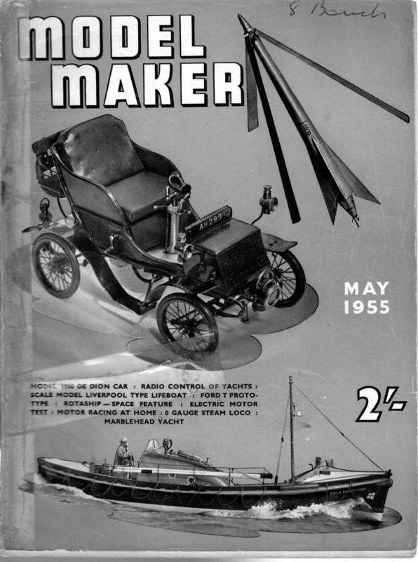
  • Petronella Marblehead 50/800 Class. By Gilbert P.M Walker.
  • Starting on the Right Tack, Part i. By D.A. MacDonald
MCD: 2 DE DION CAR : RADIO CONTROL OF-YACHTS : SCALE MODEL LIVERPOOL TYPE LIFEBOAT TYPE = ROTASHIP—SPACE FEATURE : : FORD T PROTO- ELECTRIC MOTOR TEST = MOTOR RACING AT HOME : 0 GAUGE STEAM LOCO MARBLEHEAD YACHT : i wi ” RADIO CONTROL OF THE using the XFG-1 and/or R.K.61 miniature radio tubes (commonly called valves in England). This radio operates on 465 MC. Because the 465 MC. band is such a sensitive band, the receiver was mounted at the mast M CLASS “ARROW ” head. BY LEADING AMERICAN greater the distance over which reliable control may “be had. Also it was discovered that EXPERT C. 0. DAVIS radio interference generated by the control motors on the boat is apt to cause trouble if the receiver is on or below the deck close to SERVO BATTERY the steering or sheeting motors. The receiver must be kept dry, and it was considered that the mast head is likely to remain drier than any place in or on the hull of the yacht. The yacht has even been sailed in the rain, using a light plastic bag as a cover for the radio receiver (single channel radio). FROM RECVR RELAY RUDDER MOTOR /Yifo HT LT B LIMIT “\ switcu Rudder Control The receiver controls the motor, in such a manner that the rudder position is proportional to the length of time that a transmitter signal 674 VOLT BATTERY — ag for left or right rudder is held on. Proportional control usually means a system whereby the rudder position at all times corresponds closely to the position of a control knob, wheel or lever at the transmitter. Such a control can be accomplished in many ways, but it usually involves considerable complexity, and is not to be recommended for the beginner. A time DOUBLE RELAY 2,0000 EACH SIDE 8,200 n fig 1 Ya WATT RUDDER CIRCUIT This proved an excellent arrangement, for several reasons. The receiver has an integral loop antenna which does not function properly when it is too close to any dense object, including the hull and the water. The higher the antenna above the water, the AN INFORMATIVE ARTICLE COMMON THE radio equipment used in the Arrow was the “McNabb Citizen Band” radio, proportional system, as used on the Arrow, is DIAGRAM not as glamorous as a true proportional system, 254 MAY, but it is simple to build, ‘light in weight, reliable, and the rudder can be set to any desired degree. The Arrow’s rudder is directly operated by a permanent magnet reversible geared SHEETING 1955 SYSTEM Figig 2 down electric motor. The motor used in_ this particular yacht was a “Hanson,” but any of the very good electric motors I see advertised in the MODEL MAKER will serve just as well. The gear reduction required for operation of the rudder is in the order of 2,000 or 4,000 ORUM “Sets Motor to 1, depending on the speed of the motor. If the rudder moves from the neutral position to an extreme hard over position (approxi- mately 35 degrees), in four to six seconds, the response speed is about right. than that, the yacht will be slow in turning about the buoys and in light airs, which may cause the yacht to miss her stays. On the other hand, if the rudder is too fast compared to the skipper’s response time, he will not be able to accurately set the course he desires. Some safety device is required to prevent the motor from breaking something or stalling and overheating when the rudder gets over to the extreme positions. BOWSERS If it is slower PINION 6) SHEET SECTOR GEAR On the Arrow, the safety device consists of two limit switches (V-3 Micro switches) which are actuated by the tiller in its extreme positions and shut the motor off. Some kind of a device is required to enable the operator to get either left or right rudder at will, preferably with a single radio channel, because they are the cheaper sets to buy or build. A rubber driven escapement could be used, such as is used on model aeroplanes, if it is fitted with contacts to turn the rudder motor on and off. However, rubber driven escape- ments are temperamental and delicate devices at the best and the number of operations they may perform with one winding is limited by the number of turns in the rubber bands. The Arrow is equipped with a unique relay circuit which is far superior to the common escapement for the purpose. A single signal from the transmitter always gives right rudder (regardless of which direction the rudder previously moved), and thé longer the signal is held on the farther the rudder moves. A short signal (dot) rapidly followed by a longer signal (dash) always gives left rudder. The amount of rudder movement is again dependent on the length of the dash. This device then is not, repeat not, a sequence type of escapement. The heart of this discriminating device is a double coil, three position relay (all contacts open when unenergized). The relay was obtained on the war surplus market. It has 2,000 ohm coils and double pole single throw contacts 4 y 4 a“ / if ; ! | ‘A aoe ! \ mataes ele ~ | VANE ? \ I|-4t SERVO BATTERY (Atso serves RUDDER) FEEDBACK CONTACTS CRANK on each side. If this type of relay can’t be found, a suitable relay could be home built, or the job done by mounting two conventional relays back to back with the armatures mechanically coupled together. The circuit for the rudder control is shown in Fig. 1. Its operation is as follows: The two coils of the relay are connected in parallel, but each has a series resistor as shown. One coil has a large electrolytic capacitor across it. When the circuit is energized by the closing of the sensitive relay in the receiver, the coil without the capacitor comes up to full voltage instantly, and attracts the armature to it. The other coil comes up to full voltage more slowly because the capacitor must charge up through the resistor; eventually it comes to the same voltage as the first coil, but it will not take the armature away from the first coil because of the difference in the air gap that now exists. The rudder is wired up to give right rudder with the relay in this position. If the circuit is now de-energized, the first coil loses its 255 See ‘i MODEL A coil armature and energize the rudder motor in the left rudder direction. The values of voltage, resistors and capacitor shown, are for the surplus relay described. Other relays will require different values which are best determined by experiment, to obtain the desired action. The drain on the 674 volt battery, which also serves as the receiver “B” battery, when the relay is energized as shown, is 12 milliamperes. Automatic Sail Control (not radio controlled). The Arrow has fully proportional sail control. Since its inception in 1952, fully automatic and proportional sheeting of -sails has demonstrated its superiority over radio control of sails and three position control of sails. Radio control of sails is inferior to automatic sheeting for three reasons. First, the skipper, being ashore, cannot judge the correct position of the sails as accurately as an automatic device can doit. Second, the skipper can do a better job of negotiating the course if he is relieved of the responsibility of sail setting. Third, an automatic sheeting system can be made more reliable and simple than a radio controlled system of sheeting. A wind vane is mounted on the after deck, in somewhat the manner of steering vanes used on manually controlled yachts. This vane is independent of the rudder system. It serves as a wind direction indicator to the automatic sheeting system. The vane does not move the sails directly as the vane moves the rudder on a manually controlled yacht. Since the sails must be hauled in against the wind part of the time, more power is required than is available from a vane. The power comes from an electric motor that is controlled by the vane. The sail control system is a simple form of an automatic feedback servo system. Figure system. two shows the complete sheeting The main and the jib must be rigged for simultaneous sheeting which is an old practice for the manual control skipper and so nothing need be said about it here. The two sheets are bent onto the opposite sides of a continuous travelling winch line. The winch line is a continuous line around two drums, one of which is driven (Fig. 1 approx., as shown). Now it will be seen that one drum 256 being motor driven, both sails will be hauled in or slacked, depending on the rotation of the motor. The gear ratio of the drum to the motor can be figured from the motor speed, the drum size, the required sheet travel and the desired sail setting speed. The Arrow’s sails will travel from close hauled to the running position in four seconds, which has proven quite satisfactory. A pinion is mounted on one of the drums, which engages a partial gear or gear sector. This gear carries three contacts as shown. Contacts from an old relay, or home made spring contact arm will be satisfactory. The centre contact arm is longer and is connected to the throw of the crank below the vane, by a link as shown. The centre contact arm should be quite flexible, so that a slight breeze on the vane will be sufficient to close the contact points on one side or the other, and run the motor. The motor connections are made so that the motor always runs in such a direction to cause the contact points to open again, by moving them in the direction that the vane deflected the centre point. There are other ways of accomplishing a feed back rather than the one shown. Once the principle is understood, other methods of accomplishment will become apparent. The important thing is to have the full throw of the crank equal to the full travel of the feedback points when the sails travel their full distance from run to beat. This system, like most servo systems, will oscillate, or “hunt,” if not properly adjusted. If the three contact points are extremely close together, or if the vane assembly is too heavy, the system may rapidly pump the sails in and out over a narrow range, even with no wind or with a steady wind. Hunting can be stopped in this type servo by making the space between the feedback contact points wider. Do not make them excessively wide, however, since the system becomes less sensitive to minor changes in wind direction with wide spacing. The vane must be carefully balanced so that the feather won’t swing down when the yacht heels, and thereby give false wind directions to the servo unit. The feedback linkages as shown give quite good sail settings for all different wind directions. The discriminating skipper can improve on this system to obtain optimum sail settings by more complex feedback linkages or perhaps using custom made cams. All of the sheeting mechanisms as shown are on the top of the Arrow’s deck, except the (Continued on page 292) ——— voltage rapidly. The voltage of the second coil, however, is held up for a short while by the capacitor across it. The coil with the capacitor thereon takes charge of the armature. If the circuit is re-energized by the (dash) before the capacitor discharges too far, the second coil with the capacitor will retain its hold on the MAY, 1955 MARBLEHEAD 50/800 CLASS b L 10 20 30 Fig,| “

2 me: | SEA nee! eine sas —— EE ee ee eT ie | te Oe Saree oe, | Biman EY * 3 1 2 x S : wuLL | } a Ut Stes I2ors DECK TRANSOM 12, Inner f eat rea e- i le as PAINT ‘ie a = Bee Ee er : ae ; > ee? Ss yo 280 SS ee A XS | 7 Al ay + Se yo ye cet cs med ; Paes erent Bs eed ee ASR BS ._ —s ee Fite oO ey £ Sa = oy PP a \ ee ee Ss ee Eo ee JE US THICKNESS OF ene” : ‘ See \ ee | z) pea 9 nae eS th ee ae a {2-00 * FL a 3 es La ———_ TY f 4750″ ee SS 3 SS ; ie a oft 2 peeetet ere ! : 8 y the el ef era ee , NXNN bee Se ns © — i ae TAGONALS ee eed 7 8 9 10 M ¥\ oan ~~ 49°2% LW.L ;A \ Se Bete. C.OF B. TAN7!.4* omit Am ts* Reis 507% LWL. (CANOE BoDy ONLY) . \ Maths mt 1″: 2″ N\ N. Se Pc] L~ a 6-85 a tat pxa (rR) 0-75 406 3-50 7-87 850 CM MUR ES tS) R—MEANR 3:74 TM) 2:90 <1eB4 a ‘PETRONELLA’ “B” +62 D Dx Type STERN 4 a L 6-92 3-31 0-78 15:00 13-30 8-87 7-85 4:08 1-02 = 7-65-9567 7862 234 2-69 4-4 1-16 test 13-00 AN / 10-18 ihe2 9°96 1-08 “88 RN Sef // / \\ aaaLo *¢) \ a 339 AREA (0')0-92 a PEEL RUSLY el? 5 7. h \ Oo . M / \ c.OF 8. MEAN oP\xA \ 7i N LZ.SS 1-33 12-72 “73 1:06 113 vi7 ery ‘75 4:27 Sail- plan only is shown differences as its from “A” would this plan, but such a rig is not in common use in this country at present. The sails must be made of Terylene, Union Silk has too much stretch to be suitable. The first suit of plan “B” cannot be used in so strong a wind as that of plan “A,” therefore, I would suggest that plan “B” is only used for sailing on inland not be apparent at this reduction. The tables, howthe give ever, necessary SUITABLE TERYLENE FOR information SAILS ONLY therefore carry a high sail plan. I have included two sail plans: plan “A” is conventional; I would advise that this plan be used when the boat is intended for open or sea-side lakes, and by all but the very experienced racing or sheltered lakes. Should anyone build this boat, may I wish him the best of luck with her, and may he have many successes with her. I would very much like to hear from any builders, I would particularly like to know what the exact position of the mast is, and what ratio of vane angle to rudder angle was found to be best. Finally, may I again wish any builders of “Petronella” many hours of enjoyment from skippers. It is suitable for sails made either of Terylene or Union Silk, I would advise Union Silk for the First Suit and Terylene for the rest. The second plan “B” is an experimental rig, and should not be attempted by anyone who has not had _ considerable experience. Our friends in America are now using rigs of an aspect ratio comparable with their boats. A: UNION SILK go enor A AREA= 4 200) afab 2 +73 a A b | c 1 (A)| 52| 16| 54] d | No. jee 8 we |1 (A) u (A)| 45| 15| 47; 8 | I (A) Total | —| S.A. | Ratio —— ; in. in. | in. | sq.in. sq. in. | 62 x16 | x63|| 496|| | Main |—| | | | | Luff soot ‘Leach | Area | Area| % Aspect] Luff Foot | | || Fore | 484)x14 No. B: TERYLENE | || | SPINNAKER | | x44| 303 | 799 | | (38% 388 | | | Total Leach| Area | Area| % Aspect S.A. | Ratio —| —— -—— in. | $9. in. sq. in. in. | in. 62% | 387 | 68 x14 ——! | x684 476 | 154 x14 60% | .485 799 x49 | 323 40% | .450 I | Main | 502 x14, x52) 369 | gis 00% 350 554x124 | x56 | 347 | soa 2et%_ 45 | | al | ‘ Il | Fore | 424/x13 || x38* 244 | AlL%414% 409 |40%40% 370 | 45 x 12ax12 || xA4ld) 3] 247 | | | | | | 9 | 58% | | | | | | | m (A) | 38; 14] 40| 7 | Ill (A) V (A) | 31 | 13] 33| 6 | IV (A) : | Ill | Fore | 36 x12 | x32 189 mw (e) | 50| 16) 52) 9 | I (®) IV | Main | 284) x 11d | x29%, 164 ys 54% 246 | 30hx 94| x31 | 145Tal 52% || 3il | | ss =i ore xtt | x26) 142 46% 7 313 | 294K‘ 10 || x26“ 135|| | 48%,%o || .328 | 1 (8) | 58| 17| 60| 42 15| 44 8 | Ill (8) @ (8) 10/1 ¥ (8) | 34) 14| 37 i (B) IV (B) Ht | Main | 394 x13 | x403 257 | i eo | | : | 421 gs 42%, | 342 | 37 se MN | x34 | 185 44%, 370 .304 | 43 x11 434) 236. 56% | .391 | | ! 281 il | | | | | MAY, Since the yacht alone cannot, of course, win races, we should presumably proceed to draw up a specification or a set of requirements for a successful skipper and mate. 1 certainly have not the temerity to attempt this, but as a mere scribe, I can perhaps pass on a few of the words of wisdom I have received from those most successful in this field, and a few conclusions drawn from my own observations as a race official and spectator. The first requirement is that skipper, mate and yacht should form a team. Both skipper and mate should have confidence in the yacht and in each other. The extent of the mate’s function is a matter of arrangement, and can be influenced by conditions of sailing. Often a skipper needs a mate only to turn off and occasionally retrim —at other times the business of racing is very much a two-man affair. The division of effort and responsibility should be agreed upon and fully understood from the start. There should be only one skipper—a team comprising a skipper and a mate engaged on a continuous argument has little chance of success, however good their craft may be. The skipper, at least, should have a good understanding of how a yacht sails—this knowledge is largely intuitive and to some extent good skippers are born and not made. But if every opportunity is taken during non-competitive sailing to improve this understanding, the ability to do the right thing instinctively can be quickly developed. Both skipper and mate should be fully conversant with the rules governing both racing and the rating of the yacht. Disqualifications which need not have incurred often deprive a wellhandled yacht of a place in the prize list, and do not tend to improve morale. Finally the skipper should be equipped with sufficient tools and materials to carry out minor repairs quickly and efficiently during racing. I am sure many readers will readily endorse this statement from their own experience. [ was asked by our editor to make special reference in these notes to a particular type of boat, viz—Mr. H. B. Tucker’s “Duck” series with the development of which I have been closely associated. At present two “Duck” designs are generally available, namely the 36 in. class “Donald Duck” (in two forms, one for Braine and one for Vane steering), and the M-class “Jemina Duck”. Two later designs have been produced, “Ivor Duck” (36 in.) and “Emma Duck” (M-class) but building of these is restricted at present to prototypes only. The first prototype “Ivor Duck” won the 1954 National Championship, and the first “Emma Duck” has recently been launched. A brief 285 1955 STARTING ON ‘THE RIGHT TACK AN INTRODUCTION TO MODEL YACHT RACING PART ONE—THE BASIC REQUIREMENTS BY D. A. MACDONALD recapitulation of points from the foregoing na notes as they apply to “Donald” and “Jemi these Duck would therefore be appropriate,cedas in inboats have been and are being produ creasing numbers, and have proved very successful. Both designs completely satisfy all the design requirements laid down in the opening para- graphs. It is beyond the scope of these notesn to discourse at length on the various desig features incorporated, but it should be emphasof ised that these go far beyond the mere fact secure a modified forward transom to using ies. maximum sailing length. Quite a few subtletcan these and n desig the are introduced into is, only be appreciated by a thorough analys craft these g sailin of ience supported by exper under varying conditions. As far as the constructional requirements are concerned, these all apply. some with special force. It is very 1m- portant that “Ducks” are not made overweightif; they must float on the designed L.W.L. orthe anything, a shade high. It is vital that blunt bow it not immersed until the boat is driven hard. At low speeds these craft use their fine underwater lines for easy drive, but when of heeled, they derive a considerable increaseThe stability from the powerful shoulders. transition from a gentle, easily driven hull to a very powerful one takes place smoothly, but fairly quickly, and unless the original flotation 1s plane is correct, this aspect of performance c(parti d depen also They ed. affect seriously ularly the M-class) on the sails providing the maximum possible drive per square inch under all conditions. This, with the high aspect ratio adopted in the later designs, demands special sail material. Varnished terylene is admirable, but it is also possible to use other suitably treated materials to produce a sail to will set correctly and be impervious which moisture and other influences. In the case of the M-class “Ducks” there is a special need for a positive and accurately adjusted kicking strap, and a further kicking strap, possibly incorpor(Continued on page 289)