- Drake, An MM Class Hard Chine Yacht West Country Design. By P.G. Dalton.
- A Model Catamaran, The Boat for Shallow Waters. By H.J. Halpin.
- Starting on The Right Tack, Part II, Sails. By D.A. MacDonald.
- Modelling Along
- On Planing and Planing Sail Boats, An Exhaustive Article on a Controversial Subject. By H.B. Tucker.

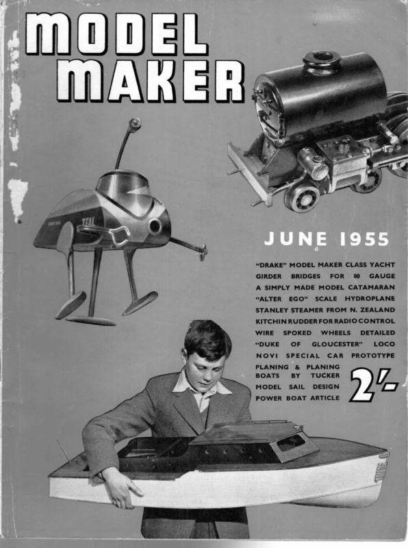
“DRAKE” MODEL MAKER CLASS YACHT GIRDER BRIDGES FOR 00 GAUGE A SIMPLY MADE MODEL CATAMARAN “ALTER EGO” SCALE HYDROPLANE STANLEY STEAMER FROM N. ZEALAND KITCHIN RUDDER FOR RADIO CONTROL WIRE SPOKED “DUKE NOVI OF WHEELS’ GLOUCESTER” SPECIAL PLANING & BOATS BY MODEL SAIL DETAILED CAR PLANING TUCKER DESIGN POWER BOAT ARTICLE LOCO PROTOTYPE WA Li
YP LONG GIRDERS To CARRY KEEL ENDS ! DRAKE M.M. CLASS ANO) SUPPORT MAST 4 x% sem , YACHT My) P.G DALTON 4 DESIGNED BY COPYRIGHT OF MODEL. MAKER PLANS SERVICE CHOCKS GLUED EACH EMBRACING RENDON RO. WATFORD. HERTS. SIDE OF GIRDERS KEEL 50% inc PLanx | Me notes DRILLED %cenrREs Y pry Fixed ii TO TAKE MAST-STEP SPINOLE $i0es, Borroms, « oeck Me pLy \ PORTION OF PLY FIN, BURIED IN KEEL DRILLED IN FIN LEAD. HOLES TO SECURE LEAD Ye GARBOARO FILLETS WOLLOWED TO FILL ANGLE SLOT ——} FOR KEEL —— Zz SKEG LI PIE SLOT FOR i | vis nee ae, [mm a76
JUNE, 1955 AN M.M. CLASS HARD CHINE YACHT viehie WEST COUNTRY DESIGN BY P. G. DALTON “FRE introduction of the M.M. yacht class created an additional stir in a hive of activity situated away down in Falmouth. This activity eminates from what must surely be a unique source—the quarters of “Westcountry Crafts”, a firm devoted entirely to the production of boats, both model and full-size. The founder of this concern, Percy Dalton, is one of the keenest model yachtsmen in our experience, and certainly one of the most enthusiastic when it comes to encouraging young blood in the sport. Among other of his products is a range of ready-built lightweight sharpie designs, 21, 28 and 36in. in length, fully finished and ready to sail at £2 17s. 6d.. £3 15s., and £5 5s. respectively. Since the introduction of our 25 in. class, Mr. Dalton tells us that he is now going to concentrate on producing 25 in. boats at £4 Ss. complete, plus the 36 in. R as above. The workshops in which these boats are produced are in what used to be the crew quarters of the old Falmouth packets, and anyone personally purchasing a boat and wanting to see it in action has only to drop it out of the window to see it sail straight up the harbour. Needless to say, the firm’s dinghy is handy for retrieving! Even such small models as this have been right through and around Falmouth Roads in a gale, and from various types of models tested under conditions such as these it is obvious that Mr. Dalton’s designs are among the most seaworthy to be found. The designer is a believer in extreme simplicity, and for this reason most of his stock designs, right up to Marblehead size, are constructed on the hard chine system, using 1/16 in. ply for bottom, sides and decks, no ribs or frames at all, and internal construction consisting only of a slight inner keel-hog, and just enough scantle shelf and chine to keep the skin together. No screws or nails are used and fin keels with lead bulbs are fitted where the tules allow. The smallest stock boat—21 in., with a displacement of 2 lb.—carries 225 sq. in. of sail in any weather on the open sea, and the strength is all that could be desired. Drake is developed from the lines of these boats, and incorporates most of the features mentioned. Also included is a “Dalton special” —no movable rudder is provided and steering, etc., is by sail trim only. The designer has sailed in competition with class boats using this system and has taken innumerable boards from boats equipped with all manner of steering de- vices. Further, the system teaches a youngster (or novice) to sail a boat properly on trim only. Construction of the model is perfectly straightforward. The shadows are first cut from scrap ply, and erected on the jigging stick as shown in the drawing. The inner keel, chine, and inwale (shelf) members are then added and the frame covered with sheets of ply, which may be bradded into position while the glue dries. Ply deck beams and the internal girders are installed, plus skeg and keel, after which the interior of the hull can be given two coats of good quality lead paint. The deck is then added, followed by the king-plank, etc. The mould for the lead can be made in plaster 315 Hl
Acorner of the Falmouth workshop, with work proceeding on various models. behind P.G.D. (second from right ) are the jigs used in producing the chine designs mentioned. Picture on preceding page shows “commercial” product with cockpit. built to supplied designs, “Westnormal on the country” system for round hulls, which uses inner diagonal planking and outer fore and aft planking, with no ribs— extremely strong and comparing very well in weight with other methods. Prices for established classes are: M.M.—£7 2s. 6d., 36 R —£9 17s. 6d., Marblehead —£12 17s. 6d., 10-rater— £15 15s., A—£24 15s. This includes keel cast and fitted, of paris using a plasticine or carved wooden pattern. The mould should be made in two symmetrical halves and provision allowed for the insertion of the foot of the fin. When everything is set up the fin is slid in place in the mould and the lead poured in; the holes drilled through the fin anchor the lead firmly in place. This step can, of course, be carried out before fitting the fin to the hull if required. At least two undercoats should skeg and rudder tube fitted, deck loose but deck beams installed, completely rubbed down, with one coat of primer. Cost may be slightly more for special awkward requirements, and considerably less for chine designs. The staff of this unusual business are all skilled boat-builders who pride themselves on “spot on” work and invite examination of their products through a magnifying glass! Models for marine museums are part of the day’s work, and Mr. Dalton exhibits regularly in the Royal Society of Miniature Painters. His exquisite marine miniatures, in oils on mahogany, have been purchased by Royalty— but this and the many other fascinating activities (last big job was a shark-fishing boat designed by P. G. D. and built by his staff!) \ now be applied to the boat and rubbed down to a glassy finish ready for a final coat of enamel. The deck may, of course, be lined with Indian ink and varnish; full descriptions of this part of building were given in previous M.M. yacht articles. An ingenious method of fitting the mast is must bow to space requirements. incorporated. This entails screwing a cup hook into the heel of the dowel mast, and cutting off the hook part to leave a projecting stub which engages LA_ holes drilled in the king—= plank. The rigging 1s conventional and carried out using screw-eyes and waterproof braided flex. The completed boat ready to sail is, as we have already mentioned, avail- able from Mr. Dalton for a very modest figure, and we feel that model yachtsmen may. also be most interested in other figures given to us for CB MEELED 20° f a” boats 316 C.8. UPRIGHT.
a A MODEL (Lee Pe ne THE BOAT FOR SHALLOW WATERS DESIGNED H. J. BY HALPIN Its bright sails and unusual layout ensure a maximum of attention at the pondside for this model Catamaran. DESIGNED BY H.J.HALPIN | i H , | san \Cabemie ; —MATE RIALS — 10. SQ. INS. OF MATERIAL FOR SAIL. 18X2°SQ. BLOCK 1Oxi6x- BEND 3 a2 OF MED. SOFT BALSA. nite Se fata THREE 3FT. STRIPS “42 DOWEL. ONE I8″STRIP’ 44;DOWEL. 3 X3FT. SHEET OF MED. SOFT BALSA. 6 SQ. INS. Ye SHEET PLY. LARGE TUBE OF BALSA, CEMENT. DETAIL OF PLY STEM BOUND TO RACK & RUDDER (NOT TO SCALE) ‘ 12 SPAR Yo DOWEL , ae oOo f ZOE ‘ok BOW f AT A’. RUDDER Vig PLY BOW AND oe 732 DOWEL STERN BOARDS.’ BALSA DOW ;
JUNE, CENTURIES old, catamarans, or surf boats, are still used extensively around the coasts of Ceylon and the port of Madras for fishing and light cargo. A striped sail of many colours and lively painted hull characterise these native craft, the subject for the accompanying model which forms a picturesque home decoration and fast efficient sailing boat, entailing only a modest outlay and a few evenings’ work. The sequence of construction is clear from the pian, and commences with fashioning the hull and outrigger from 18 in. x 2in. square and 9 in. x lin. x tin. blocks of medium soft balsa wood. A sharp knife, razor blade or craft tool and sheets of medium and fine sandpaper are the only tools necessary for the work. A gouge of the “X-Acto” type can be used to advantage, however, when hollowing out the hull. If this operation proves too difficult, the modeller need not take it to the limits shown. The balsa when waterproofed will itself provide sufficient buoyancy. Cut bulwarks, bow and stern boards from }in. medium soft balsa and drill (or pierce with a heated wire) the holes shown, 3/32in. diameter for the booms and 1/16 in. diameter for the lashings. Glue all the components apart from the out-rigger into place, using balsa cement, sand to a smooth finish and waterproof them. The quickest and most convenient method is to apply balsa cement with the fingers. By this means you close the pores and at the same time lay the “fur” retained by balsa after even the finest sanding. Prior to binding the 3/32in. diameter dowel, bulwark cappings and outrigger booms in place, mould them to shape in the steam from a kettle thoroughly dry it only remains to rig the model. First cut a ten inch square sail from lightweight fabric, preferably striped, thus avoiding the use of paint which must be waterproof paintwork from the sail’s mast, and step the complete unit into the hull attach the rigging to tie hull only by means of small hooks and eyes. The model is now ready to sail and requires a depth of no more than an inch of water. Trim the boat with small pieces of lead, (the outrigger in particular will probably require a little ballast) set a little right rudder to counteract drag and the “Cat” is ready for a straight run. Just watch it out-distance yachts of its own size. The completed hull now requires all detracts block. If it is desired to dismast model between trips to the local water, it is more convenient to a thorough painting inside and out. The model illustrated was decorated as follows. Hull block, Out-rigger, Rudder and Cargo racks, medium oak varnish stain, Hull interior and Dowelling, matt black model dope, Bulwarks, red and silver relief on royal blue ground, glossy model dope, Sail and Pennant, red and When and efficiency. Alternatively, sew together contrasting silk hair ribbons. Note that a sliver of garden cane should be sewn into the bottom hem to act as a boom. Attach the sail by sewing a length of twine into the top hem and securing at each end of the spar, bind spar to or over a lighted gas ring. orange. 1955 is In between sailing the Catamaran makes an attractive decoration for sideboard or mantelPeice. 325 mi
MOOEL MAKER) (1) STARTING ON THE RIGHT TACK (4) AN INTRODUCTION TO MODEL YACHT RACING PART TWO—SAILS: THE DRIVING POWER (S) (2) (3) BY D. A. MACDONALD a ; They thus demand similar care in design, construction and maintenance. In the case of a motor car, none of these functions can be carried out properly without some understanding of how the engine works. Similarly, All their original have been either exponents. For example, let I. IA shows the “aircraft wing” type of rig advocated in a widely-sold book on this subject. IB is an approximation of the sailplan of a yacht actually used for racing by the exponent of the IA rig (and illustrated recently in MODEL MAKER). IC represents the latest fashion from the same authority. The high aspect ratio has been abandoned; the slot effect is apparently no longer worth a light, so the jib has disappeared; the sail has no camber, and the elliptical form has been somewhat inverted. The battens and the kicking-strap, however, remain, and to compensate for the loss of the other “essentials,” we have a new piece of “mumbo-jumbo” (not illustrated) in the form of a hole in the middle of the sail, which, been written (and published) has since been contradicted in word and deed by its authors. So the novice seeking after truth is liable to fig! contentions us consider the three yachts of Fig. have proceeded to apply with enthusiasm rather than caution to yachting problems. Unfortunately, in many cases, the application was made in print before being fully tried out in practice with the result that much that has The analogy seems plausible enough at first sight, and in fact is very close to the truth under certain conditions, but these conditions are very rarely achieved in the model yacht world. If we accept the analogy unconditionally, we should come to the following conclusions:— these proved wrong in practice, or contradicted by it will not be possible to get the best out of a yacht’s sails without some understanding of how they do there job. Much has been written on this subject, particularly since the war by aeronautical experts with newly acquired knowledge of aerodynamic theories which they yacht’s sail and the wing of an aircraft. It should have a large number of battens (all horizontal) right across the sail, presumably in the manner of air- craft wing ribs. (6) It must, for maximum efficiency, be accompanied by an additional sail (the jib), whose only purpose is to provide a slot effect, in order to reduce pressure on the leeward side of the sail. (7) The yacht must always be sailed upright. | ie my introductory article of this series, I was careful to stress the importance of good sails to a successful yacht. The sails are the driving power of the vessel, and therefore correspond to the engine of a racing car. be baffled and misled, and it is not, therefore, to be wondered at that, as I said in my first article, more yachts fail through inefficient sails than for almost any other reason. The greatest of these widely-published misconceptions is the rigid analogy between a The sail should have a high aspect ratio. It should be elliptical in outline. It should have considerable “flow” or “camber.” The leach should always be kept taut by a hard kicking-strap. apart from its technical virtues, presumably acts as a spy-hole, to enable the skipper to keep an eye on his opponent. Which of the three rigs is the right one? One can only assume that, as IB appears to be the one used in racing, it is more successful than the others; after all, it is well-known that doctors are reluctant to drink their own medicine! The seventh edict, that a yacht must always be sailed upright, is abundantly proved wrong in practice. It is well-known that if a yacht will not heel in a light air, she will not point up into the wind. On manned yachts, the crew position themselves so as to heel the yacht artificially in light winds. The need for a few degrees of heel exists in all yachts, including hulls which do not change their shape in heeling. Thus it is obvious that it is the sailplan which has to be heeled to make a yacht 334 point to windward, not the hull.
JUNE, Actually, a yacht should heel less in a fast windstream than in a light air, a fact which will be understood later, and is confirmed by the finding of most skippers, that under— rather than over—canvassing is advisable in high winds. Also. the wing analogy begins to have some significance in high winds. For most model-yacht sailing purposes, we propose therefore to abandon the wing theory, but in throwing the aerodynamicists overboard, we must acknowledge, and not decry, the ultimate value of their research and experimental work. Man has been developing the sailing vessel for thousands of years. Much progress and discovery have come about by a process of evolution, with elements of “natural selection” and “survival of the fittest” as in the evolution of the animal world. In all this long history it is unlikely that there is much that has not been already tried and discarded. A study of the history of this long development process shows how the best type of craft and rig for a particular purpose has emerged from centuries of trial and error. Records of much of this work are readily available, and it is easy to trace lines of development which culminate in the final form of each type of craft. We can therefore trace a path through history, leading us to the racing sloop rig of today, and in the process learn something of the ways in which sails are used to do their work. Limitations of space prevent more than a cursory survey, but readers wishing to study 1955 Fig3 4 ¢ B “invention” and the square sail of the Vikings and Phoenicians needs no comment. What is worth noting is that Fig. IIB is a complete antithesis of the wing-sail theory exemplified in Fig. IA. Let us now move on to Fig. IITA where we have a further stage in “primitive” sail development. Emphasis appears to have been placed on the ability to sail the craft to -windward, and the form of the sail has changed from a square to a triangle with its apex at the bow, and the yard extending along the top edge of the triangle, which, in the case of the “lateen” sail shown, is curved. Fig. IIIB is again triangular, but the angle at the apex is less, and the centre line of the triangle is inclined steeply upwards. It is interesting to note that this craft is used in hot regions, where light sailing breezes, accompanied by rising air currents are prevalent. Fig. [IC is not a reversion to the square sail, but belongs to the same family as IIIB, with an extra section added. The driving force for sailing to windward appears to have been provided mainly by the original triangle, the added piece being effective down wind. this fascinating subject fully can find much of what they need to know in our libraries and museums. Fig ITA shows a most primitive form of sail. A square or rectangular sheet of fabric, set on a yard, and intended primarily to propel the boat before the wind. Presumably, at some stage in its history, it was found that this square sail could be used on a reach, and even enabled some progress to be made to windward. As a side-issue, I have shown in Fig. IIB, a form of sail for a model, demonstrated in a recent Television Inventor’s Club programme. This sail, it was claimed (and the claim was supported the model by a demonstration), could to windward, and in propel fact, it compared favourably with sloop-rigged models of similar size. The similarity of the 1954 The sails of Fig. III appear all to have been based on a section of a cone, i.e., the portion DEF of Fig. IVA. Their action appears to be based on a flow of air across the sail from D, along lines fanning out towards E and F, as illustrated in Fig. IVB. The design perimeters for such a sail are the apex angle A and the angle B between the centre line AG and the horizontal. Practical limits will be set for the height of E above deck, and this affects the selection of angles A and B, which are interdependent. We appear now to have established a conception of a conical sail. Let us now go one stage further, and consider that the fastest craft of type IIIA were those which carried two sails set close together (Fig. VA). To explain this, we can draw on the results of wind-tunnel 335 Mh
and the appar- > FORCE ot = ee | ent wind, both with and without the aid of the slot effect produced by an 6 10 20 30 40 50 60 70 60 extra sail. The B ANGLE OF ATTACK Stated otherwise, vessels only plane when overdriven. From the above, certain primary maxims arise for the design of planing craft. In order to plane easily, the boat must have a low maximum normal speed, and the weight must be reduced as much as Possible. Since length is the most important factor in determining the normal maximum speed, she will be short and beamy, rather than long and narrow in proportion to displacement. Hydroplanes naturally travel much faster than sail-driven planing boats. Moreover, their engines provide a constant and measurable thrust. Complet e and perfect planing is only found in the stepped hydroplane. The reason is that in a stepless hydroplane, or planing sailboat, lift is only applied forward, whereas in a stepped hydroplane, both ends of the boat are lifted simultaneously. Hence the stepped boat is not obliged to cock her bows up as the stepless boat must, and in addition, planing is more complete, as a higher proportion of the vessel’s bulk can be lifted from the water. This statement must be qualified, however, as given a sufficiently light hull and horse-power enough, almost any sort of hydro- plane can travel at fantastic speeds. Except for a few primary principles, hydroplanes, particularly stepped boats, have little in common with planing’ sailboats, so we now turn to planing sailboats and yachts. Planing Sail-Boats A sailing boat can only plane down-wind, and windward work calls for exactly opposite qualities to those required for planing. For good windward work, sailing length is essential, and to gain sailing length, the vessel must settle down in the water. We now see that to plane, a vessel must rise in the water, and for windward work, she must settle down. Here we have two totally different requirements almost impossible to combine in a single hull. Of 342 course, the problem is comparatively simple in dinghies and small yachts, where the crew’s weight forms a large proportion of the total weight, since by moving the crew, the fore-and-aft trim can be altered to an extent that gives the effect of several different hulls in a single boat. Of necessity, all model yachts are displacement types, and in these, design is a matter of compromis e if we are to attain some degree of planing without sacrifice of weatherliness. Per contra the designer of a planing boat has to solve the problem of a satisfactory compromise in order to have some windward ability. In the case of planing boats, however, the idea is that anything lost to weather will be more than made good on the other legs of the course with the wind free. In planing sail-boats, matters are complicated by the fact that the wind does not provide the constant thrust an engine does, but varies from day to day, and minute to minute. Moreover, it must be reasonably strong before the boat can plane at all, since a vessel cannot plane until she is overdriven. A yacht’s ability to plane is governed by the amount of sail carried in relation to displacement. Hence to a limited extent, the S.A. : Displacement ratio ( S: * D) is a standard of comparison for assessing the possibilities of a design as far as planing is concerned. Some designers prefer to use the S.A. : Wetted Surface ratio (S : W) for this purpose, but my own preference would be the S.A. : Displacement ratio, since it is only at low speeds that skin friction forms the major part of the total resistance s to forward motion. One, of course, assumes that the skin of any racing yacht is made as smooth as humanly possible. We now see that besides being as light as possible, our planing sail-boats must have a large S.A. In this connection, planing types invariably have sail plans with a low aspect ratio. A good reason for this is that these light displacement craft lack stability to carry a rig with a high C.E. Also, high-aspect ratio plans are best for windward work, and low rigs best for running. In a planing boat, the emphasis is all on sailing down-wind. Of course, the inferiority of high rigs for running is mostly overcome when the spinnaker is set. A spinnaker, particularly a large balloon spinnaker, is a lifting sail with a low aspect ratio, which greatly assists a boat to plane. In spite of the pseudo-scientific jargon and mumbo- jumbo with which some writers regale us. the design of planing governed boats solely by is a a most unscientific affair, few rough principles, rule-of- thumb methods and experience. Planing Boat Design and Aeroplane Practice It has been asserted that planing-boat design can, in certain respects, be based on aeroplane practice, particularly as regards sail plans and keel appendages. This is definitely not the case, but it may be as well to examine the matter and show why this is ridiculous. Sails and wings both work in the same element, but exercise different functions. Sails are flexible and supported by external spars. Wings are rigid and envelope the spars. Hence sails are of the same curvature back and front, though naturally the windward side is concave and the leeward side
JUNE, convex. Of course, it may be contended that sails have battens, but unless fully-battened Chinese junk sails are being used, battens are short and merely serve to prevent the after leach falling hollow, and perhaps to gain a little unmeasured S.A. The main difference, however, is that the sail is the propelling instrument of the boat, and serves the same purpose as the aeroplane’s propeller, while the wing is the plane’s support in the air! When we compare a keel appendage with a wing, we find even greater divergence, as not only do they exercise different functions, but also operate in different elements of vastly different density. The functions of the keel (or fin) are to carry outside ballast, and prevent the boat making leeway. The first of these can be disregarded in the present thesis, and we will concentrate on the second. The purpose of the fin is to resist sideways thrust, and it has no power to move the vessel in any direction. In fact, it is practically a marine anti-skid device, and functions horizontally. The wing supports the plane and functions vertically. If that was all there is to it, there might be some small excuse to imagine some analogy existed between the two, but let us follow the trail to the end. In the fin both sides are identical convex curves. In the wing, not only do the curves of top and bottom differ concave or but one practically is flat. convex I and have the heard other it con- tended that the top side of the wing does the work in supporting the plane; I have also heard it is the underside. Suppose it is the top side that pulls the plane upward. This, like the two sides of our fin, has a convex curved surface. If our fin functioned in like fashion, then the leeward face of our fin would strive to pull our boat to leeward, while presumably the windward face would try to pull her to windward. Next assume that the underside of the wing does the work. In such case, seeing both sides of our fin must be alike, in order to emulate the wing’s functions, both sides of our fin would have to be concave. A third explanation of the wing’s functioning is that both top and bottom sides play their part in supporting the plane. If so, we should have to make our fin different on each side, one convex and the other concave. This is obviously 24 ma unless we are always to sail on the same tack ! (Editor’s Note: We can accept no responsibility for our contributor’s aerodynamics ! !) This is where we run up against another theory. It is alleged that because boats sail better to windward when they carry a very slight weather helm, the deflection of the rudder from ‘’midships turns the boat’s keel appendage into a facsimile of a wing. The real explanation is infinitely thereby increases simpler. The slight helm angle serves to check the lee garboard waterstream, and its pressure. In other words, the keel has a more solid cushion to lean on, which aids it in preventing the boat crabbing to leeward. Naturally, the angle of helm needed must be slight, about 3° being usually considered the optimum amount, as a greater amount of helm would act as a brake on the craft’s speed. It will be seen that by following the argument to its logical conclusion, we reach a complete reductio-ad-absurdum, and that there are no possible grounds for comparing planing boats and aeroplanes. Planing Boats’ Fins Before turning to other subjects, let us clear up the question of planing-boat fins. is to prevent undue leeway. 1955 The fin’s purpose It is a known fact that a flat plate presents the maximum laterfal resistance for any given area at all speeds, but for various reasons, it is usually inadvisable to use a completely flat plate. Therefore, the fin waterlines are streamlined to present a minimum of resistance to forward motion. That their curvature somewhat resembles that of the upper face of a plane’s wing is just as much co-incidence, as if I meet a friend wearing a similar hat to my own! And that is all there is to it. As speed rises, lateral resistance increases, and smaller lateral area is needed. But the wind does not always blow hard, and sufficient lateral area must be retained to obviate excessive leeway in light weather. Nevertheless, it must be remembered that at low speeds, wetted surface friction forms up to 75 per cent. of the total resistances to forward motion. In planing types, fins are cut down to a bare minimum, as everything is done to encourage planing. Hence the seal-flipper fin. Planing Ability devends on the Design of the Buttocks When running, a boat sails more or less upright, and her bow lifts as planing begins. How readily she lifts depends on the angle of incidence of the forward buttocks, as these form the lifting surfaces (or planes). She rides on her after buttocks, which are her bearing surfaces. In order to get sufficient rise in the forward buttocks, and at the same time flatten and lengthen the after buttocks, planing boat designers place their greatest body depth well forward. In dinghies and similar craft, usually it is approximately one-third of the length from the bow. ; If the rise in the forward buttocks is too steep in relation to the rest of the design, trouble occurs. What happens is that the sails push the boat up-hill until a point is reached when they can no longer support the load. She then. collapses, and the sails start their Sisyphus-business all over again. The hull “porpoises”, bumps, buries the nose, or “blows up”, and the boat usually broaches wildly. This fault afflicts many displacement type models when they plane. It occurs mainly because the designer, in his anxiety to get low over-hangs, has forced a sharp turn round the midship section and drawn out his profile and buttocks as straight lines. Compare such a profile with one having an easy curve from the point of greatest body depth to the L.W.L. endings. In the latter, the steepest rise is at the L.W.L. ending, and as the profile gets deeper. it becomes increasingly less steep. When a yacht with such a profile rises to plane, the work of the sails to maintain her at planing height is less than on one with a forced profile. This, in a displacement type yacht, is another reason why the turn round in the midship section should be as easy as possible. Of course, it is only in a planing type that a very forward position for the greatest body depth can be used. In a displacement type, it is placed only a comparatively short distance ahead of the middle of the L.W.L. i It will now be clear that.the real secret of planing, both for planing and displacement types, lies almost entirely in the design of the buttocks. Other points of Design that influence Planing Another rough-and-ready guide for planing-boats designers, is the ratio of Displacement to Waterline
i MOOEL MAKER) Raillery on the length (3/D:L), and one authority states that this should not exceed 100 for easy planing. In conjunction with other points already discussed, this presages a shallow-bodied, beamy boat, which gives the further advantage of large bearing surface in the M.G, Trophy Cancellation run. In planing types, the greatest beam is placed much further forward than in displacement types, and I have seen advocated positions of one-third to two-fifths of L.W.L. length from its forward ending. Transom width is also great. One writer advocates this should be as much as four-fifths of maximum beam, but I am inclined to think this might be somewhat overdoing things. In planing boats, the greatest body depth and maximum beam often fall at the same fore-and-aft station, thus abolishing the raked mid-section. The latter is of great advantage in the design of displacement type yachts, but appears to have no Dear Sir, : As Hon. Circuit Racing Secretary of the M.C.A. may I have the use of your columns to outline the circumstances leading to the second postponement of the M.G. Trophy Meeting’ In August, 1954, the M.C.A. reached an agreement with the Patentee of certain aspects of rail racing, which was published in the December, 1954, issue. As a result of said agreement, the M.C.A. withdrew its objection to the patent which was granted forthwith. In the “Spirit of Mutual and Friendly Co- operation”’, I wrote to the Secretary of the Model Rail Racing Association inviting them to compete in the M.G. Meeting on March 13th, 1955, although they are not affiliated to the M.C.A. I received replies from the patentee (not the secretary of the M.R.C.A.) implying that if the meeting were run, he would take action against any ind:vidual (not the M.C.A. as a body) who used track attachments. other than those purchased from the patentees. merit, and possibly the reverse, in a planing boat. Let us conclude by summarising what we have learned about the design of planing boats. They must be light displacement and have a large S.A. disposed in a low aspect ratio plan. They must be shallow-bodied and beamy, with the width carried well out to the transom. Greatest body depth and maximum beam point are well forward, and often in the same fore-and-aft position. The fin area should be cut down as much as possible, and the fin deep and narrow. The model yachtsman, who builds a boat of this description, may win a race in a hundred, when conditions are just right for the type. He can weigh this possibility against the certainty of ninetynine disappointing and exasperating outings. For what it is worth. my own advice to novices is to select a design of true displacement type, because of necessity, model yachts are displacement type, but try to choose a design that has reasonable possibili- ties of planing under suitable conditions. I Now under the terms of the agreement, the patentee agreed to supply the track attachments at a reduced figure. However, members of the clubs affiliated to the M.C.A. who have written to the patentee, have been informed that the agreement only applies to clubs affiliated to the M.R.C.A., not the M.C.A. I leave your readers to judge whether the MC.A. would enter into an agreement which gives another Association (not in being at the time of the agreement) a virtual monopoly of the concessions gained by such an agreement. As official copies of the agreement had not been circulated to the M.C.A. Clubs, and therefore some members may not have been familiar with the terms, it was decided that the meeting be postponed until a am, however, not in favour of sacrificing other desirable correct understanding of the terms of agreement had qualities in favour of planing in any displacement- been reached by all concerned. I regret to inform you that this has not been possible to date. I am, Yours faithfully, E. ARMSTRONG. Hon. Sec. Circuit Racing M.C.A. type yacht. “ELLA” THE LEARNERS 33 IN. GAUGE PASSENGER HAULER We are happy to advise readers who may be in the throes of building this interesting locomotive, that we have now received a substantial further instalment, detailing the construction of PONY TRUCK and LUBRICATOR. This will be appearing in the July issue of Model Maker, following which we trust we can resume uninterrupted publication of the remainder of the model. | The last previous article on ‘‘Ella’’ appeared in November 1954 Model Maker and covered wheels, axles and eccentric sheaves. We would apologise to those whose work may have been held up, for reasons beyond our control. . ; Railing and Model Cars Dear Sir, The sting in the tail of your Editorial in the April issue will, no doubt. have drawn the replies from both Bill Moore and Ted Armstrong that I strongly suspect it was calculated to attract, and since these persons | are the M.C.A. officials most competent to deal with the matter, I shall, as a Car-Section Secretary, only comment briefly in passing. Firstly, neither cause nor effect of the “cancellation” of the first M.G. Trophy Meeting was similar to the second, since it was due to difficulties experienced by the host club, and secondly, having heard the reason for the second “cancellation”, which, should reason prevail, will only amount to postponement, I wonder if you, Mr. Editor, could think of an alternative in the circumstances? After all. we follow Rail-Car Racing as a hobby, not as a money-making business, and it would be foolhardy to expose individual club members, who have attempted to work to the “agreement”, to threats, however frivolous, until the position has been clarified. 344 f


