- The 1955 British and Open A-Class championships and the Yachting Monthly Challenge Cup International Race held at Fleetwood August 7-15th.
- Starting on the Right Tack Part III, Fitting Out the Standing Rigging. By D.A. MacDonald.
- Readers Write …
- Tucker’s Topical Talks, Some Comments on the Season’s National Championships. By H.B. Tucker.

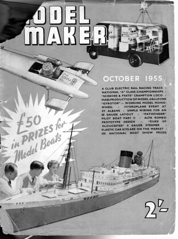
A CLUB ELECTRIC RAIL RACING TRACK NATIONAL “A” CLASS CHAMPIONSHIPS : “SCISSORS & PASTE” CRAMPTON LOCO MASS PRODUCTION OF MODEL GALLEONS “GYROTOR” — WORKING MODEL MONOHYDROPLANE EVENT AT : WHEEL ST. ALBANS : SIMPLE WIRING FOR AN “PATHFINDER” : 00 GAUGE LAYOUT ALFA ROMEO : tI PART PILOT BOAT “DUKE OF : PROTOTYPE DESIGN : GLOUCESTER” 0 GAUGE STEAMER : T MARKE THE ON PLASTIC CAR KITS ARE £50 NATIONAL BOAT SHOW { PRIZES
OCTOBER, 1955 The 1955 BRITISH & OPEN ‘A’ CLASS CHAMPIONSHIPS and the ‘YACHTING MONTHLY’ CHALLENGE CUP INTERNATIONAL RACE ‘held at Fleetwood, August 7-15th 1955 F LEETWOOD was again the scene of the British and Open A Class Championships this year, and in addition to a week’s splendid racing in this event, spectators had the opportunity of witnessing the first international race for the Yachting Monthly Cup to be held in this country since 1949. Both races gained in interest from the international flavour; our old friends Kai Ipsen (Denmark) and H. Boussy (France) were this time reinforced by F. Stout (U.S.A.) who had flown over, with his wife, from California. The one thing that marred the whole pro- gramme was the wind, which spent most of its time around the East. This means that large areas of the lake are blanketed and the wind is funnelled through the bridge (heading photo), giving untrue winds and areas of complete calm. When ‘starting from this end, “getting a fill” was largely a matter of luck, and the day on which these conditions were most noticeable was strictly a Black Friday for the two much-fancied boats Commando and Red Sabre. Commando dropped seventeen points off the reel, an incredible occurrence, and Red Sabre got away satisfactorily on only two boards all day ! With few exceptions, the standard of sailing of the 40 entries was very high; similarly, the equipment of most boats was better than in previous years, though some were still looking almost “parish-rigged”. Terylene sails and lightweight polythene spinnakers were virtually standard; notable exception was the processed nylon used by the French boat, in gorgeous colours for different suits! The O.0.D., Mr. J. Alexander, elected to sail in four fleets of 10 boats, A and B sailing alternately with C and D, then A sailing D and then C etc., making a full tournament but with smaller numbers to handle at one time and half the crews having half-day rests from Heading photo shows a general scene, including the bridge which influenced the sailing to a marked extent. Photographe r in white ducks is famous designer A. W. Littlejohn. Below, winner Moonraker leading Coppelia, and on right, Red Sabre TT
the strain. This worked so well that only one heat for the whole fleet remained to be sailed on Saturday, a fact which reflects great credit on the officials and also on the co-operation of the competitors. Saturday morning dawned with a light Westerly wind and Moonraker slightly ahead’ of Red Sabre. With five points possible for each boat, it was possible for Red Sabre to win if Moonraker dropped both beat and run; the Newcastle boat made her five but Moonraker’s successful beat pushed her into the top position by two points. Third place went to Celeste, due to the superb handling of R. Jurd and his brother, who sailed her in the early part of the week until R. J. could get to Fleetwood. One of the best of the new boats is Aramis, which won the Daily Dispatch Trophy the previous week-end. She was one of four Robertas (B. H. Priest), the others being Conquest, Finality and Roberta herself; the last-named sailed extremely well to secure fourth place (3rd in °54). Coppelia, 5th, is an enlarged Arabis and was sailed extremely well by her proxy skipper. It is an interesting thought that her lead was several pounds ‘heavier than the total all-on weight of the American boat! The Cup and prizes were presented by H. W. the Mayor of Fleetwood, and a special medallion, given by M. Boussy, went to Miss C. Corrooin, the youngest lady mate in the regatta. After receiving the congratulations of the other competitors, the winning skipper and mate were ceremoniously flung into the lake—a prophylatic treatment to obviate any chance of incipient hat-shrinkage! The Y.M. Cup After the above little ceremony, the Mayor started the first pair of the international race. Contenders were Moonraker (G.B.), as winner of the Championships, Revanche (Denmark), Viviane (France), and Magic (U.S.A.), and it had been agreed that eight rounds would be sailed. In a freshening wind some fast runs were made, fastest being Moonraker’’s 2 min. 12 sec., winning her the Wing and Wing Cup, which is awarded for the fastest time downwind during the main race. From top: The American boat Magic displays its ultra-long hull; boat in background is Bolton entry !Tosca. Next, M. Boussy releases Viviane for a run against Arthur Levison’s fill. Next, Conquest, and Ulster boat Firefly; former was still in process of tuning up. Bottom, I Cc do starts a board with Coronation. Bereted starter in upper photos is M.Y.A. racing secretary Mark Fairbrother; blazered official is Assistant 0.0.D. Frank Boardman 562
OCTOBER, cussion. Some considered it to be similar to 10-raters of 30 years ago, but on the other hand it earned itself the appellation “Spaceship”! The first striking feature was Three rounds were sailed on the Saturday, and the position when racing recommenced on the Sunday was Great Britain 33, Denmark, France and U.S.A. 19 each. A light Westerly wind was in the long, tapered bow, and the second, the plumb fore and aft edges of the keel. | Her dimensions (with Moonraker’s in parentheses) are:*-Liw.. 56und- “GS35), (63), 44lb. displacement. evidence, and as the morning wore on the lake banks were thick 6,000, with and spectators—over all the streets leading to the water were choked with parked cars! By lunchtime five rounds had been sailed, and the positions had opened out: G.B. 51, Denmark 43, France 32, and U.S.A. 24. The wind again freshened in the afternoon, and some beautiful sailing was seen. In the last heat of the seventh round Moonraker, in a tense struggle, took three points from Revanche to increase her lead and leave her requiring only two points for a clear win. The run back was started in an electric atmosphere; the crowd were kept in touch throughout by Mr. N. Frith, on the P.A. system, and a storm of applause broke when Moonraker crossed the line barely a length in front of Revanche to win her third trophy. Moonraker and Revanche are both well-known boats; Viviane is brand new and an enlarged Janine. Once over her teething troubles, she should be formidable. Most interest, however, was shown in the American ‘boat, which was beautifully built but very unorthodox, and provoked considerable disTop of page is the triple winner Moonraker; on right the magnificent Yachting Monthly Cup with the Wing and Wing Cup—the smaller is almost a foot high! Below left, Red Sabre drawing well, running neck and neck with ill. 1955 approx. beam 13.5 in. (15.6), sail area 1,160 Magic carries 38 lb. of lead; sq. in. (1,630). she is obviously a heavy weather boat, and in light winds her lack of sail is a handicap to leeward, while her lack of lateral area makes things difficult to windward. Nevertheless, she was well handled and, in her own weather, extremely fast. Once again the Mayor of Fleetwood attended for the prize-giving, which took place before a huge crowd which applauded all the skippers. M. Boussy produced another pair of medallions, one of which was presented to Mrs. Jeanne Stout (mate to Magic) for being the first lady mate ever seen in the international The races for the Y.M. Cup. * second went to J. Morley, mate to Viviane. All four skippers received a Fleetwood M.Y. and P.B.C. burgee as a memento of the event and also of the club, which celebrates its silver jubilee this year, and a further presentation was a beautifully carved plaque bearing the badges of all the Northern Centre, the lightweight Magic working to windward. Right, Commando, here seen with fill, had her mainsail holed on the first day by another boat’s spinnaker boom
Left to right—Scots entry Mercury has an unusual tosemscry position! Background boat is Viviane, sporting dark blue sails. Roberta sailed quietly and competently into a well- eserved fourth place. Coppelia finds a little wind to make this pleasing picture. Lastly, Aramis leads Embassy up the water Division clubs, given as an appreciation to H. Bradley, of Bolton, the wizard of the score sheets and racing schedules. The Regatta Dinner was held YACHTING MONTHLY CUP (Final scores) on _ the epic drn 4 Wednesday of the week, and was a most enjoyable affair. All in all, the premier regatta of 1955 was a highly successful affair and must certainly rank as one of the most outstanding ever held under the M.Y.A. flag. Viviane Reais tion I No. K. 676 Name’ Moonraker 2 3 4 5 K. 704 K. 688 Red Sabre Celeste K. 727 Coppelia 6 K, 731 Aramis K. 707 Club Roberta we ll 12 13 14 15 K. 716 K. 720 K. 500 K. 471 D. 22 Jill Juanita Elma Flame Revanche Y.M.6M.O.A. Birmingham Helensburgh Fleetwood Denmark 16 K. 514 Mercury Miniature 18 U. 522 F. 27 K. 733 20 K. 689 K. 734 21 22 23 K. 642 K. 721 K. 567 25 K. 698 K. 732 26 K. 738 27 28 29 30 31 K, 693 K. 664 Black Tarquin Conquest … K. 692 Coronation K. 621 718 706 729 702 K. 570 K. 531 K. 563 K. 730 Pinocchio Oberon Betty XII… Thunderbird Orchid Aes Tommy Tucker] Thistle Lady Love Firebrand ees Fleetwood East Hull Bolton… Birkenhead Morecambe Poole Saltcoats… Nottingham Port Glasgow Doncaster ae Littlejohn … Priest 145 Levison Jurd 143 140 Levison 132 Alexander 130 Levison 131 Daniels Daniels one W. Smith … Alexander … Ipsen = Levison Levison McGruer Dawson Ipsen 116 15 109 107 106 R. Bailey Bailey 102 Smallwood Atkinson 101 99 M. Boussy M. Tregenna “F. Smallwood H. Atkinson J. M. Fitzgerald Newcastle Priest West A. Levison eir… wus C. McKechnie E. L. Dawson K, Ipsen Bolton Fleetwood Pandora Andrews Turner Points 130 130 123 L. Paton Are W. J. Daniels A. McGruer … R. Bradley P. Mustill” Embassy Turner Builder Priest … J. Lace Alexander Morecambe … South London … Helensburgh Bolton wis North Liverpool K. 420 K, 682 36 40 tee 29 Priest an Las Corby after Feltwell] Alexander … an F. Stout * U.S.A. B. H. Priest … W. H. Jones L. Corrooin … . | T. Todd Ulster Bradford Ulster Felixstowe K. K. K. K. 37 France Ulster Firefly Finality Tosca oes Berkeley, U.S.A. Viviane Shangarry Wildfire Evaine 2.X% ees Birkenhead Birkenhead Southend Vixen IV Marian 32 33 34 35 38 Magic … Fe. J. Lofthouse … Commando Shikara Scamp … aes Doncaster K. 711 K. 723 K. 530 50 F. Stout Designer Y.M.6M.O.A. 9 France CHAMPIONSHIPS Kirtley & Andrews… R. Jurd si oes D. Lippett J. Anderton … Birmingham 56 H. Boussy for fastest run downwind—Moonraker, 2 min. 12 sec. P. West Newcastle Gosport … 75 Denmark Race stopped after 7 rounds Skipper Portsmouth Great Britain K. Ipsen… WING AND WING CUP BRITISH AND OPEN CLASS Posi- P. West P. Holbrook … F. Shackleton J.F.Craker … P,. L. Windsor W. F. Hugman Stout i Boussy wee W. J. Daniel Turner Priest : Turner te Daniels McGruer Norsworthy Priest Alexander … Alexander … Corby Andrews R. Bailey Alexander … Stout … 123 Boussy -s. | 102 R. H. Tregenna | 101 Paton … Daniels McGruer Bradley Mustill… 97 94 93 93 87 H. Fitzgerald * Tregenna Corby 86 85 83 Craker… 82 Bailey 80 Alexander 78 F. Dutton a J. Roberts H. Amlot J. Parkinson Littlejohn … Littlejohn … Priest ner J. Parkinson V. Crean Tucker H. & C. Poole 63 Daniels Lapsley 55 SS J.T. G. Bissett J. Lapsley J. Lynn D. Riley 5€4 Tucker Daniels Tucker Levison Roberts Amlot … Parkinson Bissett J. McMillan Boardman 77 71 69 66 zis 56 55 45
OCTOBER, 1955 sailplane thereby decreased. With the foregoing requirements in mind, let us therefore proceed to evolve from first principles a satisfactory arrangement for mast and standing rigging, and decide on materials and methods to be used. First consider the solid cone of Fig.I. This, as a mast structure, is essentially rigid, and, with an adequate width at the base, would be self-supporting. It would stand a heavy down thrust if required, and would have a low centre of gravity. But it would be heavy, and the windage would be excessive. As a first step, the cone could be hollow, and the weight thereby reduced very considerably, with very little loss of rigidity. To reduce the wind1 age, the width at the base Fig would have to be reduced considerably, in fact, to the point where the windage ceased to have an appreciable effect on the performance of the yacht. The sacrifice in rigidity would then be overcome to a sufficient extent by the use of-external supporters, e.g., wire stays. If the basic conical form is maintained, the loss of The above little table shows that the ratio of 128 produces masts of suitable and typical proportions in the smaller classes; the slightly lower ratio in the case of the A-class is perhaps also appropriate in view of the relatively greater sail pressure and weight in this class. This little rule of thumb should be useful in deciding proportions for masts for yachts of other sizes. Let us now compare the conical mast form of Fig. III with masts of other types. Fig. IIIa shows a type of mast often used on model yachts. This type, which is usually of solid wood, has its greatest diameter about 1/3rd of the way up, and is circular in cross-section. In fact, it is something like the form used for and archer’s bow, and, in fact behaves like one when subjected to the down thrust of shrouds and jib stay. It invariably bows under the pressure and has to be straightened as far as possible by additional shrouds attached to the widest part, so adding more weight and windage. The centre of gravity is also high, and unless the diameter is generous, such masts are liable to snap at the deck, where the diameter is less than maximum. Fig. IIb shows a commonly used and effective mast, cheap and simple to make. It consists of a straight metal tube of circular section, with a topmast of solid wood, tapered SSS inherent stability is minimised. This gives us the mast of Fig. II (which is not drawn to scale). The ratio I/d is chosen for the best out as follows:— Length of Class of Yacht A 10-rater M 36 in. mast (1) 94 in. 80 in. 72 in. 64 in. Diam. at 2 in. Zin. | Ratio 2 in. | 125 truck (d/2) base (d) + in. din. Diam. at | | + in. 2 in. din. I/d | 138 128 128 ! 4 compromise between stability and windage, a suitable figure for 1/d being in the range of 125 to 128. In typical cases this would work AE excess wind pressure. (2) The passage of air around the sails will be disturbed and the efficiency of the BY D. A. MACDONALD \ \ | I \ Fig Il Fig [a Fig Tb Fig IIc | | | \ { Be (1) Excessive windage will cause the boat to heel more under the pressure of the wind, and to be driven to leeward by the AN INTRODUCTION TO MODEL YACHT RACING PART THREE: FITTING OUT (2) THE STANDING RIGGING =I) for two reasons:— THE RIGHT TACK — = can be set up accurately, without strain on the sailcloth. The first requirement is for adequate rigidity; the weight should be kept down to 4a minimum without prejudice to this rigidity. There are further requirements, not hitherto explained, namely that the windage of mast and rigging must be kept as small as possible, STARTING ON L ie of the essential requirements laid down .in the first part of this series was that the mast and standing rigging must provide a light but rigid assembly upon which the sails
as required, the taper being usually arrangedto provide a straight edge for the luff of the mainsail. The tube usually extends to a point at or just above the spider band holding the shrouds and jibstay. Fig IIIc represents the familiar “fishing rod” mast. This is a commercial drawn tapered tube (steel or fibreglass), parallel for about 4rd of its length, and tapered for the remainder. It is made for use as a fishing rod and its shape is therefore more suitable for this purpose than for a mast. But if a large part of the straight portion is discarded, it corresponds closely to Fig. II, and, provided the proportions are suitable, it is then perfectly satisfactory. Two other types of simple mast are worthy of mention. Firstly, since solid wood masts are still popular, these are most satisfactory when made in the form of Fig. IJ. Such a mast would not be as effective as the hollow metal one as shown, because for equal rigidity it would have greater weight and much greater diameter. But it would not be subject to the corrosion troubles which affect metal masts, an important point for yachts sailed in salt water. Secondly, there is the hollow wooden mast, which I always admire as a piece of ‘craftsmanship. For maximum rigidity, it would have the form of Fig. II, but would need to be of considerably . greater diameter than the metal equivalent, but not necessarily greater weight. It is particularly suitable for A-class yachts, where a greater I/d ratio can be tolerated, as explained above. The other classes, however, with narrow sailplans of limited area, are not well served by such a mast, chiefly because of the wind eddies produced All the mast forms circular cross section, generally agreed that near the luff of the sail. so far described have a but it is by no means this (although the most common form) is the best. At first sight, the streamlined mast, with the luff of the sail efficiently snugged in, is an attractive propo- sition, since it can reduce wind eddies round the luff of the sail and so improve its efficiency. But to do this effectively, it must rotate with the sail, and this involves mechanical complications which most model yachtsmen would tather avoid. Also, the lateral cross section dimension is reduced, and this means a loss of rigidity, so that spreaders and topmast shrouds have to be added. These set up a fresh set of wind eddies and so offset at least a part of the advantage gained. Masts of the Fig. II type would not need these extra stays, if made to the I/d ratios given, provided that the forestay and main shrouds are attached to a point 568 75% or more of the main hoist from the deck, as is the case in most modern yachts. The general conclusion to be drawn from the foregoing brief study of mast types is that, in general, masts of the type of Fig. II are to be preferred, i.e… a tubular metal mast of 2/1 taper and an 1/d ratio of about 125-128. This straight-taper tube gives the best all-round performance, combining rigidity, light weight, small windage, and low centre of gravity. Unfortunately, such masts are not readily obtainable. The “Fishing-road” type of Fig. IIIc is, however, marketed, and the steel version is suitable for the 10-rater, and larger boats of the M-class. The writer has no experience of the fibreglass fishing rod mast, but presumably it could be adapted for M-class and 36 in. class, boats, provided 1/d were made 125 rather than 128. Information from readers with experience of these masts would be welcomed. The writer has, however, used several masts of the type shown in Fig. IIIb on 36 in. and Mclass yachts with complete satisfaction, using the dimensions shown in the table above. A similar mast to the dimensions shown for an A-class, and made of duralumin tube and spruce, is at present in use on one of the heaviest yachts in the class, and appears to be entirely satisfactory. We have now to fit the mast into the yacht, and the first decision to make is whether to step the mast or the deck, or to carry the mast through the deck and step it on to the keel. If the yacht is to have a sliding rig, the former method would normally be employed. A sliding rig is unnecessary on a correctly balanced yacht, and there is little evidence to show that the few yachts in this country equipped in this way are likely to excel in racing. We may therefore safely advise the novice to avoid sliding rigs, and, in fact, to avoid stepping the mast on deck in any case. With a normally rigged boat, the disadvantages of the method easily outweigh any small advantages it has to offer. Some adjustment of mast position is, of course, essential, and the normal method of providing this adjustment is to pass the mast through a movable mast slide on the deck, and to step it on to a rack which also provides for moying the mast fore and aft. Thus by the use of both slide and rack, the position, and also the rake of the mast can be adjusted within limits. A varia- tion of one inch on either side of the designed position should be quite adequate for any youn which has been correctly designed and ult.
MODEL MAKER) Readers write… The applicable to their size of model—they do not, however, know if they are going to find an impossible consumption figure: some kind of standardised load consumption figure must be given. And incidentally, what an appallingly high amperage is usually consumed by the motors you review! For over a year now all the members of our club have used iust one motor, ex-W.D., to drive models varying from 6ft. 6in. to 4ft.. weight 75 1b. to 40]b.. at over 4 m.p-h. My own 48in. Battleship, weight 40 ]b., twin 3-bladed props, has been timed at 4.4 m.p.h. on slightly ruffled water, with two of these motors fitted, each geared down 9:7, each run off 12v. through two 6 v. accummulators, and making a total elegant little plastic walletcontaining chrome vanadium double – ended B.A, spanners in the hard-toget model sizes will which be pre- sented to our **Readers Write” amperage consumption of .75amp. on load. Con- sumption off load is 300 milliamps. A similar speed is attained by a 6ft. 6in. liner, weight 751b., run by one motor only off 12 volts, cor- respondents. consumption on load .6 amps. This motor being A.C./D.C., it is possible to tap off 74 volts A.C. for Wee Free Wee Sixes Wanted ! Dear Sir, lighting portholes, etc., at night when the motor 1s on load from 12 volt D.C. supply. I am writing on behalf of the “ways and means” committee of the Alexandra and Dennistoun Model Yacht Clubs. ; In August our clubhouse was broken into and eighteen boats, including past and present British and Scottish champions, were completely destroyed. The reason for this mass destruction was the lead keels. The timely arrival of the police, however, prevented the vandals from escaping with their loot. Another half-hour and the two clubs would have been completely boatless. Some of these boats were owned by young lads who, for financial and other reasons, have no hope of replacing them. I am therefore appealing on their behalf to anyone in England—where the 6 metre class is now more or less defunct—that if you have a 6 metre that you no longer sail or is maybe taking up unnecessary room, would you give it to one of these lads? We Frankly, we are amazed that you have not long ago featured this well-known motor. No motor you have so far reviewed can produce consumption figures to match this, and the motor costs 5s., postage 6d., from a well-known Birmingham firm! Yours sincerely, Dr. S. K. KELLETT-SMiTH. Guernsey, C.I. More Schooner Drawings Please ! Dear Sir, May I add my support to all fellow-readers of the MopDEL MAKER, now campaigning for schooner drawings and instructions. Mr. D. S. Jones, of Radlett, also has my support when he says the MODEL MAKER should be a weekly publication. A month is too long to wait. Yours faithfully, R. WILLIAMS. Aldridge, Staffs. will make all necessary cartage arrangements at this end. For the sake of these lads, and the sport, I sincerely hope that this appeal does not fall upon deaf ears. All communications regarding this matter should be sent to the undermentioned address. Yours sincerely, ‘ H. CaTTELL, Commodore, A.M.Y.C. c/o Brown, 129 Bellfield Street. Glasgow, E.1. Circular Arc Stability Dear Sir, In an article of your July issue, Mr. Tucker made a few references to concentric circular sections with circular arc profile. He appears to be convinced that the entry and delivery should not be similar, whereas it is my experience that some models with short entry relative to delivery and others with long entry delivery have performed equally satisfactorily. He states “the reason the entry should be shorter and bluffer than the delivery is obvious … the bow Standard Tests for Electric Motors Dear Sir, I write in support of your correspondent D. S. Jones (M.M., September, 1955). Your M.M. Motor Tests are excellent, but the all-important point— what amperage will the motor take when on load, is necessarily omitted, as none of these motors are tested in a standard model boat with a standard gear down and standard propeller. This would not be too complicated a test to perform on a selected few motors; two hulls, say 30in. and 40in., two 3-bladed props, and a gear down system of say 3:1, would give quite invaluable information. Your readers, after all, can gather what size motor is meets water that is not in motion and has to push this aside. The delivery has deal with water already in motion”. Now Colin Archer advocated an entry long relative to delivery, using the same argument as Mr. Tucker. It therefore seemed to me that a compromise was worth testing. In my opinion the compromise, entry similar to delivery, works extremely satisfactorily. Trial has shown too these boats plane very efficiently and that a “run” is not essential for good planing. Mr. Tucker rightly points out that a hull sisting of concentric circular sections possesses no form stability, but it would appear that in the 578 that long conhullcase
——————e ———— ve = OCTOBER, 1955 of a deep-keeled hull this is no material disadvantage. As the angle of heel successively increases, the righting effect of the low centre of gravity increases in proportion to the size of the angle of heel. Simultaneously the wind on the sails diminishes in proportion to the cosine of the angle of heel. Should anyone wish to try out a boat with concentric circular sections with an entry shorter or longer than the delivery, he has only to choose a profile of his own choice to achieve this end, and to fit the circular sections to this profile. So long as the boat floats with her line of sectional centres parallel to water, she will be as well “balanced” as if she had a true arciform profile. For perfect static “balance” an effort should be made to place the centre of buoyancy of the fin as near as possible under the centre of buoyancy of the canoe body. Again, should anyone wish the hull to possess a degree of hull-form stability, let him flair out the sections thus, by suit ably raising the line of centres from 1 to 2, 2 to 3, etc., and increasing the radius t : . . Guy Blogg’s) circula yaobt Manatesr. > intrusion into the ane. ce ponden corres which showed up well recent by appropriately. sr reombe gi he Spot The line of metacentres raised successively is from 1 to 4 throughout all sections along the boat’s length, thereby effecting hull-form positive stability, successively increasing as boat heels. Such boat’s submerged shape will not now remain constant as in the case of true circular sections. Yours faithfully, G. BLOGG. London N.W.3. Help Wanted on Colouring lvory Dear Sir, I have two very detailed models of ships—The Prince (1666), and the Ark Royal of Queen Elizabeth the First’s Navy. I was helped over the construction of The Prince by the late Sir G. Laird Clowes, and I have a set of crew and officers carved very minutely in ivory for both ships—the scale of The Prince being 1/48 and of the Ark Royal 1/96. I have made many enquiries regarding the colouring of these (really exquisite) carvings, but have received no very useful or convincing replies. Paint of any sort—even water-colours—does not seem satisfactory, as it “blunts” the very fine details of the carving, representing, as one of your writers observed, in scale 48 and 96 coats of paint! I did think snooker balls were probably treated with some stain which is absorbed by the ivory; but I should be most grateful as a regular reader of your magazine, if you would kindly give me the benefit of your advice, or put me in touch with one of your readers who is likely to have knowledge of this matter. Yours faithfully, Bric. Sm G. T. FISHER, K.B.E, C.S.I., C.LE. Woking. Those Dooling Compression Ratios Dear Sir, It is now three years since I last ran my Dooling 61 engined car in competition and I therefore trust that will not be resented recent theI experts. ion in the, sit agree with A. N. races at Hove Other that vagueness exists regarding the compression-ratios (please do not confuse with OPTIMUM compression-ratio) of the various series types of Dooling 61 engines. Indeed I hoped that R. A. Brownson would clarify this matter, but find that the mystery is now more profound than ever. Mr. Brownson gives the following figures :— Dooling 61 “A” (7.1: 1), Dooling 61 “BY” (11:1) and since the displacement of this engine is 9.946 c.c. (stroke 0.75 in.) the equivalent combustion space yolumes will be 1.631 c.c. and 0.995 c.c. respectively (i.e.) 0.636 c.c. difference or approximately 0.048 in. of cylinder. On the other hand in his descriptions of the three types of cylinder heads the equivalent difference would appear to be 0.020 in. and I therefore have considerable difficulty in reconciling the figures. Before the advent of the Series ‘B’ in 1950, a contemporary magazine gave the compression ratio figure of 9.5:1 for the Dooling 61 (with SparkIgnition Head) and it is interesting to note that this is equivalent to the generally accepted figure for High (or should we say higher) compression heads (46 to 48 units). If such a head is raised by approximately 0.010 in. a ratio is obtained approximating to the 50 to 54 unit figure quoted by Peter Hugo (MODEL MAKER, October, 1951) and raising the head yet another 0.010 in. since the Hugo figure was higher than Standard, results in an initial figure of approximately 7.8: 1. practical side, from personal experience, a On the and a Series Standard “A” gave 59 units (7.7:1)very much like “B” gave 45 units (9.8:1). I would Mr. to know if the compression-ratios quoted by “B” Brownson for both the Standard “A” and Series engines are official Dooling figures. May I take advantage of this opportunity to congratulate Mr. R. A. Brownson in writing such an excellent and well illustrated series of articles. Sunderland. 579 aa rrnieaieeneeaite | Yours faithfully, KEN PROCTER.
EE ea WODED, ge, UCKER’S SOME TOPICAL . XY COMMENTS went NATIONAL ae QNE of the most interesting debutantes at Fleet- wood this year was Sir R. Fairey’s A-class “Evaine”, a full-keeler, designed, built and sailed by Mr. W. J. Daniels. It is interesting to recall that in 1928 Mr. R. Fairey, who then owned the Fife-designed 12-metre yacht “Modesty”, commissioned Mr. Daniels to build an A-class model from her lines. Naturally, the design of a full-sized 12-Metres required considerable adaptation to make the boat fit the A-class rating tule. This was, however, very skilfully done, and the resulting full-keel model was one of the handsomest craft ever built to the rule. She was only completed just before the 1928 Gosport Regatta, but Mr. Daniels got her going so well that she finished second with 108 points, only two points behind the winner, “Little Nell” (A. Jones, Gosport M.Y.C.). Twenty-seven years later, in 1955, Mr. Daniels received another commission from Sir R. Fairey to build another full-keel A-class model. This boat is called “Evaine” after another of the owner’s fullsized yachts, but this time, instead of being adapted from the full-size design, she is an original Daniels : The new boat is an extremely interesting design with many unusual features. “Evaine” is 56.0in. on the L.W.L. and displaces 67 1b. This gives her about 541b. lead in her keel and her S.A. is rather over 1,600 sq. in. In spite of her big displacement, she is a long, narrow, deep-bodied craft. The designer managed this by packing much of her displacement into the heavily bulbed keel and full garboards. The full-keel is long on top and short at the bottom, which gives a sharply raked sternpost, on which is hung the deep, narrow rudder. “Evaine” is not designed about a raking midsection, but both the Point of greatest Beam and the point of greatest Body Depth fall exactly at the middle of the L.W.L. The C.B. is also at the same point. Further, the after part of the Curve of Areas (including keel) is an exact replica of the forward half, and both halves are almost perfect Curves of Versed Sines. This, of course, means that the boat is of the cod’s-head and mackerel-tail consequently, type. the She is forward very profile deep-chested, rises steeply easily, but immediately he took the all shapes, seams opened and the strakes dropped into hollows between ribs. With great patience, he got her back to shape, and to hold her, CHAMPIONSHIPS creation. very hull off the moulds, trouble started, and the planking ON THE SEASON’S TALKS Another friend built a planked A-class. The wood worked gave the entire inside a coat of resin glue. This seemed to have done the trick, but added about a pound to the weight of the hull. However, the work proceeded, and she was decked, painted, and ready to fit out. Then without warning she more or less blew up over night, and when the builder came to look at her, about eight strakes on each side were split down the middle. As a result, the hull had to be scrapped. So, if the Manager at your Timber Yard offers Parana Pine, you know what to say to him! aii ee A major disappointment this year was the failure of the 36 in. Restricted Class National Championship to attract sufficient entries to warrant the race being held. This class, together with two smaller classes (24 in. and 30 in. L.O.A.), was instituted as an introductory class for beginners in model yachting, and for use on sailing 24in. and waters 30in. too the forward overhang is short. It is a very clever design, but I would not contend that she is nearly ‘as pretty a craft as “Modesty”. “Evaine” did not do well at Fleetwood, but both skipper and mate complained of steering trouble. What she will do, when these teething troubles are sorted out, remains to be seen. ee As many model yachtsmen will be building new yachts this winter, may I give them a timely warning against the use of parana pine. One of my friends built a bread-and-butter hull of this wood to one of my “Duck” designs. Before painting was finished, the skeg warped out of line. It held fairly well in the laminated hull construction, but a new skeg had to be fitted. 588 for were larger still-born boats. and The failed to take on because they were no bigger than toyshop boats, and regarded by the public as childish. Likewise, they were found too small for serious racing. The 36 in. Class was, however, an immediate success and many boats have been built to it. At present, over 250 are on the M.Y.A. Register. Why, then, did the Championship not fill? I suggest that the answer may be found in the choice of venue for the race. I know the Poole M.Y.C. handle big races admirably and in particular the M-Class Championship there in 1954 was most successful, but possibly the water is rather large and too exposed for these small boats, for it cannot be denied that in certain winds quite a nasty sea gets up across the duckboards Boating which Lake enclose and one surges side of through the the sailing wee Moreover, the local club do not use the 36 in. Class. Possibly, the solution is to be found by staging the race in future years on. waters like Dovercourt, Clapham, etc., which are more suitable for small boats, and also where there is a strong local fleet of the class. I feel that if this is done, the Championships is far more likely to attract an entry worthy of the class. and and small classes


