- Caribbee, 1/24th Scale Ocean Racing Yawl. By R.E. Moore.
- Argus, Semi-scale Wishbone Schooner. Designed By H.E. Andrews.
- Starting On The Right Tack, Fitting Out The Standing Rigging. By D.A. MacDonald.
- Tucker’s Topical Talks, Tips on the Constructional Side. By H.B. Tucker.

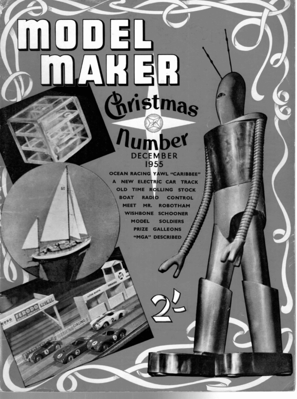
DECEMBER 1955 OCEAN RACING YAWL “CARIBBEE” A NEW OLD ELECTRIC TIME BOAT MEET RADIO) MR. MODEL TRACK STOCK CONTROL ROBOTHAM WISHBONE PRIZE CAR ROLLING SCHOONER SOLDIERS GALLEONS “MGA” DESCRIBED
[EARIBREE, DESIGNED (ees BY R.GMMoore COPYRIGHT MODEL MAKER 38, CLARENDON OF PLANS RO, SERVICE WATFORD, t : HERTS CAPSTAN Ze, LIGHT BEADING LAUNORY STUO TINFOIL REFLECTOR a WITH Rlalo Or KGAA A216 Cong Re Nam TMM PLY yy 1M PLY , P&S LIGHTS I-18 5G PIANO * “HOLES FOR BRASS sours ie sa sa sinch WOOD PLUG BRASS STRIP anass ORY MAHOGANY BINNACLE cLUTCH aD Fi GREY BLACK CHIMNEY CAPSTAN \VARNISHEO 1 MM. PLY / FORSAIL SHEET/ SELF IGNITING FLOAT YELLOW WITH ‘ / 5 Kemanocany & PRESS~/ STUD ALL OTHER/RIGGING A STATIC [WHITE CARPET THREAD RED : LETTERING sa WANS BIRCH CAPSTAN FROM BLOCK & P, ner z ee ~ PORTHOLES FROM 20 SWG LAUNDRY STUDS ~~ NG BRASS WIRE, BENT TO WHITE RA WHITE WITH RUSTY MOUTH st HAMMERED FLAT, AND GLUED ee a i ara her 5 pineees * oO / he A fs ( . WHITE —— ee =_\) \ 5) aS OC) fa X pole ORS ee Py YZ YF Me 5 z ae & 2 Sa a \ PIANO VARNISHED HAND \ | wis | “ WAY COVER EMERALD GREEN bs \ fe aes woe — a5 / ) \ SCREW EYE FOR FORESAIL we DECK IMM PLY IN 2 HALVES = WP MSs \ Nw poor arracHment FAIR LEAD & TWINE COILED ON WHITE ALL RIGGING STATIC ExceryT DIRECTIONAL WIRELESS AERIAL COMPANION — FAKE UNGLAZED PORTHOLE TRIANGULAR BULWARK STRENGTHENERS (PORT AS WELL) AN RAIL Ji SHEET Ye MAHOGANY CENTRE BOARD CASE COVERING le HAND RAIL ? — poe: oe CAPSTAN Swe ae — RA; oP oe i copper MAIN BOOM CRUTCH 18 SWG SOLDERED TO BRASS SCREWS TOP SURFACES JI8 SHEET | MM PL \ REEL ¥ NOTE: THESE ENDS ON ALL BEAMS MUST FIT NOT NISHEO | MM. PLY THE P CARVING, – PLAN ee eae rt a WHITE RAIL Ws, 8/2, 8 O/\,- SAME EXCEPT ec om t FOR LENGTH FOR ENGTH ges COCKPIT SEATS & ENGINE ROOM ROOF 46 MAHocany {va THE COMPLETE, FULLY-DETAILED DRAWINGS FOR THIS MAGNIFICENT SCALE WORKING MODEL ARE AVAILABLE ON THREE LARGE SHEETS, THE FIRST OF WHICH IS REPRODUCED ABOVE AT APPROXIMATELY 1/5 SCALE, PRICE PER SET IS 15/- POST FREE, FROM MODEL MAKER PLANS SERVICE, 38 CLARENDON ROAD, WATFORD, HERTS. ! –4-
é. ARIBBEE, a comparatively old yacht with every mod. con., and home comfort, has had an outstanding record, with success after success against her more spartan rivals. She not only came first in the 1952 TransAtlantic Race, winning Class I, but also had three years of continuous success in America beforehand. Not content with this, she won three out of four starts at Cowes in competi- tion with the British Ocean Racing Fleet, finally winning the New York Y.C. Challenge Cup, still in tip-top condition. Most of her rivals have either been lightdisplacement vessels, or those built to the most modern configurations that stipulate minimum weight with a deep draught, narrow beam, and long overhang. Caribbee, however, has a very broad beam and shallow draught, with a centre-board, an unheard of thing on any British yacht of her size (58 ft. L.O.A.). In her owner’s, Carleton Mitchell’s, own words before he began the Trans-Atlantic—“Caribbeeis about as different as possible, being the heaviest of heavy displacement boats: beamy, ruggedly constructed, with all the comforts of the home—wide bunks, big galley, bookcases, fireplace—the works. Plus two banks of storage batteries and a diesel engine”. He forgot to mention the three lavatories, the immense ice-box, the well-stocked larder (3,750 lb.), and an amazing assortment of tools covering four trades. These facts make it seem that there is some681 thing unusual about the Caribbee, but in fact she is perfectly conventional, and was the normal boat of her time, but is now rare because the majority of her class no longer exist. The only new devices incorporated in her, that I know of, are the bath and the spinnaker pole deck sockets, neither of which can have any bearing on her actual sailing capacity. The bath is unusual in as much as it consists of a canvas bag suspended between the lifelines and the cabin hand-rails, and works on the principle that as the air is generally hotter than the water, then if the bath is filled sometime before use, the water should have become warmer! The spinnaker pole fixings, consist of a pair of sockets that hold the pole in the manner of a bicycle pump and thus eliminate lashings. The Hull The first essential is a flat building board, large enough to accommodate the Starboard and Port halves of the hull, which are built simultaneously and cemented together after removal from the board. The hull is built up of 3in. thick (full) laminations. I warn you now that undersized wood should not be used, mine was 1/64in. proud. You will note that each half is built up of 10 laminations. Sections 11 A and B being sandwiched in between, when the two halves are assembled. First trace all sections on to the timber. For ease of carving, keep the grain running in the same direction, i.ec., keep the bow of the
TNOOEL MAKER! sections facing the same end of the timber. Now cut the sections out, I used a treadle saw, fectly well. Place sections 10 on the building board so that they are “deck” to “deck” and “bow” to “bow”, the deck lines should be 2in. to 3in. apart to allow for cramping. Trace the building template on to.a piece of cardboard and cut out. Take this template and hold it vertically on the deck line of one of the sections. Lay section 9 on top of 10 and align by the appropriate “step”. Mark the position round section 9 with a pencil. Remove template and thoroughly cement the sections together. Cramping is done by means of strips of wood roughly lin. x 14 in. section, about 8in. long to allow for the full depth of the boat. Holes are drilled about 1 ft. from the ends and two countersunk 3in. screws complete the cramp. Any number of cramps can be used, but six for each side is sufficient. Having got one side to this stage, take the template and repeat on the other side. When ready, remove the cramps, take section 8, align it as before, and do not forget to mark it. Cement and, of course, cramp as before. There is one very important thing, the space beneath section 9 should be packed with 3 in. plank to stop the pressure of the cramps bowing it. I saved the wood cut from the inner sections expressly for this purpose. This may sound wasteful but as most of the rest of the main structure is of the same material, nothing is wasted. There is no fear of this packing sticking because it is placed under the section which has already set hard. When this is in place, screw down the cramps as tight as you can. As before, repeat the action for the other This process is half, and leave to harden. repeated for each section INCLUDING the packing. When it is found necessary, longer screws will have to be substituted in the Make Now for one or two tips. cramps. sure with a set square that the deckline of each half is perpendicular to the building board, section by section; should one slip a little, ignore it and make sure the next one is true, Make sure the pressure of the cramps does not bow the wood either lengthwise or crosswise. When ABSOLUTELY SET, remove the two halves. ‘Note that the sections 11 A and B are cut to the finished contour in order to provide a datum line. Take these sections, align them on each half separately, and draw round them, cement them and then sandwich them between the two halves of the hull. Place the hull with the deckline flat on the building board. Nine cramps were used with packing to cramp the When set, it can be whole thing solid. removed from the board for examination. Carving To carve the outside of the hull, a plank is laid on the deck, about 6 in. longer than the boat, and a screw bow and stern is driven into the hull from the back of the plank. To carve the inside, the board is removed, and a rough cradle is built of scrap wood and covered with dusters. Carving is done with chisels, gouges, rasps, and glasspaper. It is advisable to do a bit to the inside and then a bit to the outside. Calipers should be used frequently, and the thinner the carving the better the boat. Try and get it to a little below }in. Another tip— an electric bulb held inside the boat will make When fully carved and thin places visible. This smoothed, the sheerline can be cut. should be done by placing the hull upside down on the building board. The centre line of the deck on the side view on the plan can be used as a datum. Use a strip of paper to measure distances from this datum to the sheerline. Do not forget to allow for the bulwarks shown on the plan, and mark this distance vertically This on the hull from the building board. can be roughly cut with chisels, but left 1/16 in. proud to allow for final sandings. (To be continued) 682
hl & ARG US b e SEMI-SCALE WISHBONE SCHOONER T HIS boat has been designed in response to the requests received from readers during recent months. There are many variations in schooners, both in rig and hull form, and no one reader specified any particular type. It was therefore decided to produce one of the later developments of the rig, and the yacht here shown should both perform well, and at the same time form an effective model for show case purposes. It should be stated that the lines are not those of a full-size yacht adapted for model use, they have been drawn and calculated as a true sailing model. The traditional home of schooners is the eastern seaboard of North America, and this design is typical of the many fine yachts produced there. The following notes will assist intending builders to interpret the design which has been drawn and represents a 60 ft. yacht. Hull Construction of the hull should not prove too difficult, and although one of the two traditional methods, rib and plank or “Bread and Butter” is recommended, other methods are not ruled out. Whichever method is used, however, great care must be exercised to keep down the weight. Any reduction in the weight of lead to compensate for increased hull weight will inevitably have a serious effect on the boat’s power to carry her sail. Displacement is 64 1b., lead weight 4 Ib. If plank building is employed, the use of Honduras mahogany is recommended, and if care is used, a plank thickness of 1/16in. is feasible. This will provide ample strength if the planking is edge-glued with resin glue. The deck should be made of 1/16 in. resinbonded ply, and before fitting, apertures should be cut in way of the well and deckhouse ARGUS’ FU (H PRI MA DO
IGNED BY H. E. ANDREWS ‘E structures, and 4 in. wood blocks should be glued on the underside, as indicated on the deck beam plan, in order that the sheet horses can be securely screwed down. For the best effect, the deck should be painted and lined as detailed by Mr. MacDonald in a recent article. The lining and kingplank are indicated on the deck plan drawing. The well and deckhouse should be pre-fabricated and should be made a nice push fit in the deck aperture provided. When fitting, it should be glued in place with resin glue, and a }in. quarter round beading should be affixed in the angle between the deck and the deckhouse sides. The well should, of course, be made watertight, and the bulkhead between the well and the deckhouse can be lined to represent COPIES OF THIS PLAN ENGTH 30 in.) ARE AVAILABLE 6 POST FREE FROM’ MODEL Mr. Max Aitken’s schooner Lumberjack, which served as the basic prototype on which Argus is based (Photo: Beken Bros, Cowes) PLANS SERVICE, 38 CLARENLOAD, WATFORD, HERTS. cabin doors. Details of the well seat are apparent from the drawings, and a grating for the well floor can be made by cutting a piece of Bristol board to fit, lining it in the form of a grating and cutting out the alternate squares in the lined pattern. It should then be glued to the well floor and varnished overall. The skylight should be made removable in order that access to the interior of the hull may be obtained if necessary. The well, deckhouse and skylight should be made of cedar, if obtain- able, otherwise any, and mahog- any of the transparent plastic can be used for the glazing. Rigging details Sails. The sails should be made of union silk and taped, hemmed and fitted with eyelets and hooks, as in normal model racing yacht practice. To secure scale appearance they should be pencil lined as indicated in the sail plan, or, preferably, cross sewn using light brown “Sylko” with a loose tension on the sewing machine. A row of reef eyelets is indicated in the mainsail, and these should be inserted as shown in order that the sail can be reefed using a cord lacing. The other sails are not reefed but are taken off as the wind increases. A parachute spinnaker is drawn and this can be used as necessary. Masts. It is suggested that 3 in. Birmabright tubes be used for these, with tapered spruce top masts socketed in. The spreaders should be made of mahogany, socketed into the mast bands as shown in the sketch of these fittings. Wire jack stays should be rigged up the after sides of the masts so that luffs of the mainsail and the wishbone sail can be hooked thereto. Holes should be drilled at 3in. intervals in the masts in a fore and aft direction, and 1/16in. split pins should be passed through the holes, the wire being then passed through the eyes in the split pins and secured at top and bottom, maintaining a tight tension in the wire. (Continued overleaf) 695 ew
| es Pe ee ee! > ae MODEL MAKER! “ARGUS” SCHOONER (continued) Running rigging. For ease of operation, normal model racing yacht practice should be followed. Fittings. Only two of the fittings are out of the ordinary run and call for special mention. Details of the wishbone gaff are clear from the drawing. The main members should be of ash and should be steamed and shaped over a former. The goosenecks and the outer end plates can be either riveted or bolted on The triangular plate (using 10BA bolts). should be loosely riveted to the spar end plates as movement has to take place at these points. The sail outhaul should be passed through the forward centre hole in the triangular plate and should have a bowsie adjustment to a screw eye placed about one third down the length of either of the arms. The sheet should be hooked to the outer hole in the triangular placed. The spar needs no halyards to hold A NEW 3D GAME it in place, when the sail is set the spar assumes : its correct position. The steering gear is an adaptation of the now obsolescent “Braine” gear. The amount of helm depends upon the position of the The tiller bars slides upon the tiller bars. should be made of 1/16in. brass wire and the slides should be a fairly tight sliding fit. The tiller will need to be curved up at its inboard end but the amount of curvature must be determined by experiment. A +in. elastic band will suffice for the centring line, one part being passed each side of the rudder stock. For those who are not familiar with a parachute spinnaker, the sketches show how to cut it and how to rig it. In size, its width should be twice the width of the fore triangle, and the length of the luff and leach should be the height of the fore triangle plus 2 in. For the boat to remain in character, all fittings should be finished the natural brass or gunmetal colour. Only fittings which are of use in the working of the yacht have been shown, and it is doubtful if weight schedule will allow the addition of any scale fittings for decorative purposes. For those, however, who wish to add halyard and sheet winches, backstay levers, anchor winch, etc., details of these fittings can be obtained from the yachting press. In conclusion, I would say that designing this boat has been a considerable change from designing boats to the M.Y.A. classes to which I have hitherto been accustomed, but the boat should perform well. BY J. G. RICHARDSON EADERS will recollect that in the December, 1954, issue of MopEL Maker, details were published of a game called “Cosmic Chequers”. The puzzle now described was based on the cube formed by the playing decks of the chequerboard, and the design is such that the missile can be seen throughout its journey from starting point to finishing point, but the angular journey cannot be traced by eye. Materials required for a small puzzle are about 4 sq. ft. of acrylic sheet or Perspex in the region of 4 in. or 3/16 in. thick, which might © well be obtained as an “offcut’”, and Perspex cement or balsa cement. The cube sides and planes are first cut from the sheet, working to lines lightly scribed on the material with a gramophone needle embedded in the end of a dowel or inserted in a pin vice. The saw used can be a fine tenon saw or one of the new razor saws in a holder. Care with the saw and a flat cut will guard against cracking of the material. With the saw handy, the baffle pieces can be cut in a long strip or strips ready for trimming to size prior to assembly. Fig. 1 gives the basic sizes, the constructor must add in dimension “T”, which is the allowance for thickness of material. Next, the No. 12 4in. diameter drillings can 696
ll roo STARTING ON THE RIGHT TACK AN INTRODUCTION TO MODEL YACHT RACING PART THREE: FITTING OUT (2) THE STANDING (continued) RIGGING BY D. A. MACDONALD OUR next problem is to provide adequat e staying for the mast, and the conventional form of mast staying in its simplest form is shown in Fig. 1. A” represents the jibstay (shown attached direct to deck for ease of explanation), “B” and “C” are shrouds attached to the deck edge at points behind the is mast. ‘The to provide primary the purpose necessary of lateral these shrouds rigidity. By attaching them to the gunwales at points aft of the mast they also counteract the forward pull of the jibstay and thus provide in addition a measure of fore-and-aft stability. When shrouds and jibstay are attached to the mast at a sufficiently high point, the top portion of the mast is short enough to need no further support. This arrangement as it stands provides adequate staying for small models (up to, say, 36 in.). There are, however, shortcomings which begin to become troublesome in larger craft. Firstly, modern designs are tending to put a larger proportion of the allotted sail area into the jib, giving a long-footed sail. The forward pull of the jibstay is thereby increased, and to keep it really taut (an absolute essential for efficient sailing io windward), the shrouds would have to be set up either well aft of the mast, or with a considerable tension. In addition, modern sailplans with a tall narrow mainsail usually require the mainboom to be well squared off for running before the wind, and this is impossible when the shrouds are carried well aft. Excessive tension on the shrouds also imposes heavy downthrust on the mast and a severe strain on the hull. As a result it is usually necessary to provide two sets of conditions :— 1. For sailing to windward, shrouds are set well aft to maintain a taut jibstay without undue strain on mast or hull. 2. For running before the wind, shrouds are set only skghtly aft of the mast, allowing the mainsail to be set sufficiently free. ae ER To meet both, requires two sets of shrouds as in Fig. II. “A” represents the jibstay, as before; “B” and “C” are the normal shrouds, and “D” and “E” are the additional shrouds used only when sailing close-hauled. When running before the wind, these “beating” shrouds are not used and the boom can be set free. However, the forward pressure on mainsail, jib, and spinnaker can cause the mast to bow forward, and this must be prevented, if only to avoid a risk of breaking or distorting the mast. A light backstay (“F” in Fig. II) is therefore advisable to prevent the top of the mast pulling too far forward. On reaching courses, the weather beating shroud can be set up and the lee beating shroud released. Fig. II therefore shows in outline the complete standing rigging for a mast of the types recommended in my previous article, and no further staying should be necessary. We can now pass on to the details of how this rigging may be carried out in practice. Firstly, all stays and shrouds (except possibly the backstay in the smaller classes) should be of stainless steel wire. Cord, however strong, should not be used as it will shrink and stretch, so causing the trim of the yacht to vary. Its elasticity also prevents the set-up being made truly rigid, and rigidity is an absolute essential for the standing rigging. There are advantages in both single core and stranded wire. The latter has the disadvantage of stretching for a period when new, and, except for certain special kinds, tends to develop kinks. But it is easier to make-off and attach the ends neatly to mast and deck fittings, and it can even be spliced. On the whole, I prefer a substantial single wire for main shrouds; stranded wire, if available in suitable sizes, can be used for other stays. The table below suggests suitable gauges (s.w.g.) for single strand wires for the various functions, in the four popular yacht classes :— Class MainShrouds 36 in. 24 M 10R 22 20 A BeatingShrouds Jibstay Backstay 26 26 cord. 24 22 24 24 26 26 (if required) 20 19 \, 706 22 24
TM > Me LC Fig 10 In general it is gauge, as this better to use a substantial wire enables the rigidity to be obtained without excessive tension. A taut, thin wire is easily snapped in a collision, and this could result in serious damage. To tension the shrouds accurately, turnbuckles (or wire strainers) are essential, for all the above classes of yachts. Locknuts or some other device will_be required to prevent them working upsetting the trim of the yacht. loose and so The forestay, once the yacht has been tuned up and the mast positions and rake established, could be made of a fixed length, with no provision for adjustment. This fixed length then ensures that the mast is subsequently always set up correctly once the shrouds have been made tight. The trim of the yacht is thus maintained when it is dismantled and re-assembled. There are several methods of attaching the wire shrouds to the mast fittings and turnbuckles, and many cut hands and fingers result from leaving wire ends uncovered. The usual method of terminating single strand wire shrouds is to twist the end as in Fig. Ill. Fig. IV shows a rather neater method. In both cases, the twisted or bound portion should be covered by a tight fitting sleeve (Polythene or P.V.C. sleeving is suitable), and this can be bound into place if necessary with silk or nylon thread (Fig. V). For stranded wire, the ends should be separated out as in Fig. VI and each strand in turn twisted into place, The bound giving a neat finish as in Fig. VII, portion should then be covered with sleeving as Soldering is possible only with the nonbefore. magnetic varieties of stainless steel wire—these, unfor- tunately are not easily obtainable in this country. But the binding in Fig. V can be of thin copper wire, and solder can be run into the binding to secure it and also provide a smooth external surface. ‘if Fig. VIIL shows a simple mast fitting which provides for attachment of shrouds (the screw. eyes should be substantial lugs for the larger classes, eyes or lugs A being brazed_ into It also position. provides for attaching the plate B, which the accommodates main halliard, jibstay, jib halliard and spinnaker hoist. This fitting should be pegged into the mast, since the band tension alone will not always prevent it slipping down jibstay. under the pull of shrouds and Fig. IX shows a simple fitting to provide deck plates for both main and beating shrouds. It is made of two pieces of T-section brass, joined by a runner of brass rod (3/32 in. to 4 in. diam.) on which a simple travelling hook is captive. The free holes of the main shroud plate A provide for attaching the main shrouds. The beating shrouds are attached to the captive hook B. When the beating shrouds are not in use, the hook is left free > and these shrouds are thereby slacked off. When the hook is pulled back and hooked into a subsidiary plate at C, the beating shrouds are then taut. The backstay on most models is liable to foul the roach unless it is spread back at the top of the mast. Fig. X shows a simple fitting for this purpose. The spreader bar must be fairly rigid in both planes otherwise it will bend downwards and slacken the backstay, or bend sideways and develop kinks. It must also be light, to reduce weight at the top of the mast. The fitting shown is made of a piece of tube A to which is A thin tube C is slotted brazed a flat strip B. to fit over the top of the strip and is soldered into position. This provides the necessary lateral stiffening, and the whole fitting is light and rigid. On yachts fitted with vane steering gear, the backstay is also in danger of fouling the vane feather. When the gear is well inboard, the backstay can be taken to the transom of the yacht. When the gear is aft of the rudder post it is usually necessary to take it to a point just behind the end of the mainboom. In either case it is often necessary to split the backstay at some point above the top of the vane feather and lead the two ends to points on the gunwales. The split portion of the backstay can be made of suitable cord (preferably terylene or fibreglass), with a simple bowsie adjustment, since the backstay is not normally set taut and does not influence the trim of the yacht. In the latter case, the points of attachment usually need to be selected with care to avoid fouling either the vane gear, mainsail roach or main boom. The gunwale eyes for the backstays should therefore be fitted only when the initial fitting-out of the yacht is otherwise complete, or alternatively a shroud plate with several attachment points, similar to that used for main shrouds, should be provided in order that the points of attachment can be varied if required. Fig. XI shows the princivle usually employed for attaching a jibstay. It is hooked to the mast at A, and to The latter is the jib-boom at B. fixed to the deck (via the usual jib rack) from a fixed point on the The jibstay is then boom at C. hauled up tight thereby pulling the clew of the jib hard down, thus keeping the leach of the sail taut. A If the luff of the sail were used as the stay, and pulled taut, the,sail would soon _ be stretched out of shape. The stay is therefore tensioned independently; the jib is hooked to the main-boom as in Fig. XII, the luff adjusted for tension as in Fig. XII, anda “laced” to the jib-stay by series of luff hooks or luff rings. (For Figs. XII and XIll see next instalment) (To be continued) fig It
ll MODEL AS r Tucker’s Topical Talks > H. B. T. OFFERS SOME PRACTICAL TIPS ON THE CONSTRUCTIONAL SIDE .e RECENTLY I received a letter from a reader who is building a yacht to plans obtained from the MopEL Maker Plans Service. He complained that the prints had stretched, and that the stretch was not even over the whole print. He sent the plan for inspection and pointed out Model yacht builders have quite rightly turned from casein glues to resin glues, such as Aerolite 300, but not all of them have appreciated that these glues have certain snags, especially in breadand-butter construction. Some months ago, I had occasion to compare the Rating Certificate of an A-class yacht with the designer’s figures. There were quite a few discrepancies, but the first thing that struck me was that the boat’s midship depth, obtained by adding the midship freeboard to the draught, was approximately {in. more than that shown on the plans. Enquiry elicited that she was built bread-and-butter on the W.L.s and glued up with resin glue, and in that, lay the answer as to how she had come out entirely different from design. Resin glues are water-resistant and casein glues are not. Further, resin glues make a much stronger joint. On the other hand, one can get a _ hairline glue joint with casein, which is impossible with that as the boat’s L.O.A. was given as 77.0 in., the resin glue. Actually resin glues are gap filling. half-size drawings should measure 38.5 in. overall, This makes them extremely useful to the rib-andbut were in fact about tin. too long. Now a stretch plank builder as his edge-to-edge plank fitting need of +in. on 38.5in. is 1 in 308, but as he used “not be so meticulously exact, since the glue can the term “about,” we can call this 1 in 300. be relied on to fill gaps up to 0.05 in. The best form of resin glue for model yacht In reply I pointed out that measurements are not taken from the far end of the ship, but from the building is a “separate application” type. This nearest intersection of the straight lines which repremeans that the resin is spread on one of the surfaces -sent W.L.s, buttocks and sections in the three plans to be joined, and the acid catalyst (or hardener) on the other. The glue only starts to set when which constitute a set of lines. Since W.u.s and buttocks the two surfaces are brought into contact. Only were spaced at 1 in. intervals, and sections at 5.5 in., sufficient pressure to ensure the surfaces being in on the half-sized lines, he could never be more than contact is required. O.Sin. or 2.75in. from the nearest intersection. Now the resin is thick and treacly, and imposHence the maximum possible error represented sible to spread as thinly as a less viscid glue. 1/300th of these distances, or 0.00016 in. and In parenthesis, I may mention that with Aerolite 0.0083 in. respectively. As the finest pencil line is powder glue, an extra 10 per cent. of water can be 0.01 in. wide and lines on a print 0.02 in., differences used when making up the resin. This is over and of well under these limits can be ignored. Yacht above the quantity of water stipulated by makers. building is hand work, not precision engineering, It will not detract from the strength of the joint and model yacht builders have not instruments to measure ten-thousandths of an inch, even if wood was a material that could be worked so precisely. Let us consider for a moment the prints themselves, and the original drawings from which these were made. Paper in itself is a material which moves appreciably within limits. It both contracts and expands, though it expands more than it contracts. It stretches as it is worked on, and erasures Atmospheric temperature and increase expansion. humidity also have an effect. Different kinds of paper—tracing paper, drawing paper, tracing cloth, etc., all move, but at different rates of expansion and In every case the movement is contraction, comparatively small, but the effects are cumulative, and make it impossible to produce a finalised print Yet if that is absolutely perfect in every detail. the prints are used aright by the worker, such minor discrepancies do not affect the value, and the resulIt is simply a tant boat will be true to design. question of the worker getting his straight lines correctly spaced and making all right angles an exact 90°. Then if measurements are taken from the nearest intersection of the basic straight lines, everything should be in order. I may add that it is always advisable, whenever possible, to work from a faired line on the plans. Thus when the profile is wanted, it should be taken from the sheer plan, rather than from the W.L. endings in the W.L. plan or the centreline in the body plan. * * in the least, but will add about 50 per cent. to the time required for complete hardening. On the other hand, it makes the resin easier to spread, and thus assists bread-and-butter builders to get a thinner glue-line. Even if this ‘is done, however, glue lines will. To get thin glue of necessity, be fairly thick. lines, as much pressure should be applied as possible, but even then the glue line will be thick enough to affect the construction. Turning back to the A-class yacht referred to above, from gunwale to the sole of the keel, there were sixteen lin. layers, and that implies fifteen glued joints. If each of these was 0.05 in. thick, it can easily be seen where that extra jin. came from. Now, how does one get over this difficulty? always come out exactly 0.05 in. thick, and one could get the saw-mills to plane timber to an But exact 0.95in., the matter would be easy. obviously one cannot, so the solution rests with the actual builder himself. We start by glueing the top two layers together. When they are sufficiently set, we gauge them accurately and see how one 1s working much they exceed our 2 in. (supposing to W.L.s at lin. spacing). A shaving or two is then planed off the bottom of the lower layer until we have our exact 2in. The reason why the bottom face is planed off instead of the top is that our most important markings are on the top face. (Continued on page 717) # 714 Of course, if one was certain that the glue line would


