- Witch, A New Marblehead By B.H. Priest.
- Vane Gear from Portugal, By M.Leitao.
- Circular Arc 10-Raters. By Guy Blogg.
- Tucker’s Topical Talks – Glass Fibre : Names : Plans. By H.B. Tucker.

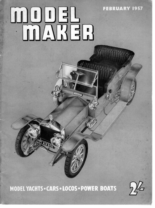
MOOEL MAKER! OUBTLESS many readers will remember 66 @ \ \ ) 1t ch 99 the previous Marblehead design MAKER. It A writer’s Witchcraft, which was published in the MoDEL NEW was stated at that time that she was designed for the advanced skipper who wanted a winning boat. It was further pointed out that the fullness of the for’d flare and’ tumblehome M ARBLEHE AD aft were put in to endeavour to counteract the desire found in most boats to the rule to put their nose under when driven hard on the run BY and then broach. Witchcraft has proved a most successful design in the North. Quite a number have been produced to the lines and, in most cases, if – B. H. PRIEST, M.I.Mar.L correctly handled, have won big races or at x | least won very high positions. What numbers have been produced in the South and how they WITCH DESIGNED BY B.H.Priest M.L.Mar. E| COPYRIGHT MODEL MAKER 38, ce | | \ CLAR END on | a oO. OF PLANS war FORD, SERVICE : WE arts. 2 FORD. POSITION OF MAST ON SLIDING RIG 4 > – 5 Res” \ (S fET POSITION OF MAST | | ON SLIDING Ric vl ae | 6 eee Te ee . z \ DISPLACEMENT 23 -25LBS SECTIONS WATERLINES 4.9″ |. 0″ Et = 70 == SS
FEBRUARY, have fared the writer unfortunately has no record. A very close observation has been made of the Northern editions of the design under all conditions. It has been decided that although good all-round boats, they are at their best to windward. Under all-round conditions it has been observed that they are slightly inferior to the Walter Jones skippered Floriana to windward, and her equal under most favourable conditions. They are not as good on the run as Floriana. But Floriana is a most exceptional ship and unless, as is hoped, Witch can better her, is very confidently tipped the 1957 National Marblehead Champion. Witchcraft would appear to be equal or slightly better to wind- So much for form in which the designer has endeavoured to be as honest as he possibly can. Notwithstanding all the effort put in the design to permit the hardest driving down wind Witchcraft proved little better than the usual run of Marbleheads. Driven hard she drove tight under, until the decks were some inches under water. Fortunately her balance was so good that driving she did ahead not broach under water. but kept on Floriana does exactly the same and a very pretty Lewis design stands vertically on her nose. Now running straight completely submerged may look very interesting but it is not the fastest method. To do that there is only one answer and that is on top of the water in a full plane. : When it was decided to design Witch the basic aims were : 1. To design a boat which in the hands of a top-class skipper could win the National Championship. To equal Witchcraft in light conditions windward and completely outsail her tN ward than the Tucker Duck design under all except heavy conditions, and a better boat on the run in all conditions than the Duck. 1957 : CA. RUDDER STOCK 8 C/L VANE TO TILLER LINKAGE as soon as weight came in the wind. ag 3. To design a boat which would lift and ‘plane instead of drive under. 10 x eae NE oe ” We will consider point No. 3 first. Nearly every effort on the part of British designers to produce a boat which will permit hard driving down wind has failed. It can be done by shortening the water line length and so by using an l.w.l. of about 44in. or 45 in. allow a degree of reserve buoyancy forward by the oes use of overhangs, most of which being put in for’’d. 68° \) \ \ ON This, however, loses out on windward work against a long waterline boat. A boat drives under because of the depress- \+—-Position oF MAST SLIDING RI WHEN RUNNING ing effect of the sail plan. How great this effect is can be gauged if the reader endeavours SAIL_AREA MAIN 64KI6%-5 = 512%”, 1B Stk “25S” _267 799°” NOTE MAINS & JIBS 040″ VARNISHED TERYLENE SPINNAKER -QO1S* POLYTHENE to push a Marblehead vertically downwards until the decks are submerged. What makes Sin. to 6in. for’d of the CB. That is the matters worse is that this effect is concentrated moment of C.E. to C.B. The only real answer to the problem is to use a modified version of a sliding rig. The mast should be positioned, after tuning up, to the correct position for windward work and either a catch lock fitted or the deck marked, so that the mast can always be returned to the correct beatin g position after it has been found. For runnin g the mast must be moved as far aft as the oe sliding rig will permit. This will cure the desire to drive the bow under once and for all. Further to assist the running of the new design it will be noted that whilst Witchcraft
MODE MAKER) had vee sections Witch has “U” sections with 47 in. in the former to what is probably the most that can be got in practice out of the rule. That is 49 in. extremely flat floors. Turning to point No. 2. To make Witch a more powerful boat in stronger winds than Witchcraft and at the same time to remain at least her equal in lighter conditions it was decided to keep the l.w.l. beam at least no longer than that of Witchcraft. In fact the lw.l. beam of the latter is 10.6in. against 10.5 in. in the former case. To make the new boat faster and more powerful in heavy winds, yet retaining the same lw.l. beam for not too much power in light winds, can only be done two ways. Firstly by a deep vee section and as this section is weak some three or four pounds extra displacement would be needed. This method is not good, as speed either to windward or downwind in fresh breezes is dependent for the main on the amount of energy used by the hull in making a wave formation. The deeper the body of a ship the deeper the wave formation it makes and the more power is required to produce the deep wave. Further a deep vee hull heels easily and so the sail plan is not so efficient as The new body section is such that the in and out wedges are so similar that when driving to windward the boat will not climb out of the water, become weaker and also lose l.w.l. length. All this has been done at the expense of 14 1b. extra weight and 4in. extra draft on a shallower body and less beam. Turning to the first point made in the conception of the design, whilst it is admitted that a designer can never be 100% certain, as the basic ideas put into Witchcraft are retained, as are balance and similar positions of C.B., and as it is 95% certain that the new ideas in Witch will give the predicted results, then, with the excellent results produced by the Witchcraft, the designer can say with almost certainty, “If it is correctly built and sailed with top-class championship skill, here is a winner !” Finally when finished the boat must weigh between 23.25 and 23.50lb. and not a fraction more. If the boat weighs more a block of lead must be drilled out of the keel is on a hull which is more nearly vertical. The same reasoning can be applied to the keel and as a result the deep vee hull will make more leeway than a hull sailed more upright. The problem was tackled as shown in the exactly over the C.G. lead. Some who build her may not wish to contend the highest honours and not wish to go to the trouble of fitting a sliding rig. For those the correct mast position will be between section No. 5 and lin. for’d of this section. Those fitting a sliding rig will require to offset the hatch. design which is the most powerful hull which can be designed for any I.w.l. beam. Wave formation has been reduced by reducing the 34in. body depth of Witchcraft to 3in. in Witch. The l.w.l. has been increased from . vane assembly and clamp 784 RIAL, a re E) ——# being formed around the shank of a drill. Hard soldering is only fe.) ig required in two places; at the joint between the vane disc and tube B, because the soldering line is too thin for anything else, with a tendency to come adrift after a limited number of course settings, and to fix the stops to strip F. All the other components do not 1 + 64″ xq” © bear any stress and do not require hard soldering; soft solder is used merely to hold them in place. It must be remembered that hard soldering anneals brass and the lighter may seem strange, but 5/32 in. is the diameter of the rods in Meccano sets and will permit the use of Meccano parts No. 63 for the counterweight (it comes tapped and equipped with parts will eventually be bent out of shape with use; furthermore, it is extremely difficult to set-screws), while 9/64 in. is roughly the inside diameter of thin-walled 3/16 in. brass tubing. The brass strip employed is 3/64 in. x 4 in. and ali brass wire is 1/16in. A piece of 1/32 in. brass for the clips of the vane assembly, clamp silver-solder larger items with a mouth pipe, because they lose the heat very rapidly and the silver alloy will not fuse into the joint properly. ‘ The drawings are self-explanatory, with the possible exception of parts X and Y. These are small tubes used to make radio connections and are obtainable at any radio parts shop. They are machine-made, with the tip turned in and a rib located a short distance from the other end. They come in several sizes which fit nicely into one another. Tubing is } in. and 3/16 in., and brass rod is 5/32 in. and 9/64in. The last two dimensions E and the vane disc completes the list of. brass stock required. Part X-sits on top of post B and is softsoldered in place. Part Y supports the vane assembly, which is slipped over it and soldered too, together with the guying arm. The vane assembly itself is begun at the top, with a piece of 1/16in. brass wire bent double: the two legs are passed through the various 1/32 in. clips and bent at the proper places, at the same 74
FEBRUARY, time, all joints receiving a touch of soft solder. The two adjusting screws on part F pass through two Meccano parts No. 59, which are tapped by the manufacturer as shown, retaining ring makes the assembly permanent. Pivot A has a small washer soldered to it, to hold it in place after the linkage arm is soldered to the vane disc. The second washer but which must have a flat filed on them for attachment to the T-section. It is quite a job to solder a flat strip at right angles on top of serves simply as a stop, to prevent the pivot from being pushed too far into the deck tube. By sawing a piece of 3/16 in. tubing lengthwise and fitting it to the end of the counterweight arm, a close fit will be obtained inside the 4 in. tubing forming the horizontal arm of a round tube, but by using a T-section sitting in a slot, for part F, perfect alignment is a simple matter, both horizontally and crosswise. A hole is drilled through the centre of part F and through the lower side of part D to take a piece of tubing (a small tube like part X will do very nicely) for a 1/16 in. centering pin, and a similar piece is fitted to the pointer of the part D. piece of jin. tubing sawn Linkage pin C is a rivet, or a bolt soldered in place and filed flat. With a linkage arm of 14 in. and a slot in the tiller beginning 23in. away from the rudder post and 1} in. long, leverage will be sufficie nt to prevent the vane from being overpo wered vane assembly, for automatic alignment. A 1957 lengthwise by the rudder of a Marblehead yacht. A distance between stops of lin. and a pointer (on the vane assembly) of 1 in. will give a vane angle of about 30° on either side of the fore and aft line, adjustable down to zero. If a serves as a retaining ring to hold down the vane assembly on post B. The latter is passed through part D, through the lower clip of the vane assembly, through the retaining ring and finally into part Y, after 3 balls have been placed therein. A spot of soft solder on the greater angle is required, increase the distance between stops to 14 in. to obtain 45°. —_— a D. A. MACDONALD REPORTS ON THE VANE 1 SEE no reason why this gear should not perform in the same way as the Weeks type, but both have a fundamental fault in that there is no toggle action in the self-tacking mechanism. This mechanism should open to the stop limit on the slightest heel angle, and stay open to the limit until the yacht changes tack and begins to heel the other way. It must not close up when the yacht comes upright, otherwise the boat will turn into the wind in a calm patch, and then shake up, possibly going about on the wrong tack when she finds the wind again. Normal vane gears such as the Lassel and Fisher types have of spring with adjustable tension on the Portuguese drawing. This simple toggle would make either of these “non-schismatic” gears operate reasona bly well, is correctly adjusted, but the adjustm ent might be rather critical in light wind conditions. Comment by Manuel Leitao Re. your criticism of the lack of toggle action, I must hasten to inform you that this aspect of the problem is precisely the one that preoccu pied me the most when designing the vane. However, although there is only a single pivot, I will endeavour to show that the deficiency is, in fact, only apparen t. a toggle action which is provided by the use of separate arms for vane and counterweight. Even so, a satisfactory toggle action is only secured when the outer ends of the arms considerably outweigh the inner ends with the slot and pin. Referring to the enclosed sketch, moments Al and B1 should be much greater than moments A2 and B2 respectively. On many Fisher and Lassel type gears, it is neces- sary to reinforce the toggle action by a tension spring between vane feather and weight arm. I suggest that both the Weeks and Leitao gears should have an external toggle, otherwise they cannot work satisfactorily at all. I have indicated an arrangement STOP a AR ~ Indeed, upon examination of the accompa nying sketch, it will readily be seen that, when the boat heels, the vane feather, which is heavier than the pointer of the vane assembly, rotates around the main pivot and falls to leeward, pushing said pointer up to windward. At the same time, the whole of the weighted balancing arm rotates around the same pivot and falls leeward, pulling at the S, which is mounted on it, the same way. Therefore, at the point S there VANE ARM WEIGHT ARM are two forces in opposition, which ensure constant pressure of the pointer against the stop, regardless of Al Vis,
MOoEL MAKER the position of the vane feather. This action becomes instantly evident when one handles the actual vane. Promptly and continues on the original tack without loss Final Observations by D. A. MacDonald The action of this gear does in one sense give a of way. Until the yacht is put firmly about (e.g. by poling off from the shore) the vane gear will not move from its original fully open position. form of toggle action, but this interpretation of a toggle is not the one normally applied to a vane gear, since the pressure required to hold the pointer against the stop is only present when the yacht is actually heeled. When the yacht meets a heading puff of The action of the Leitao vane, is, a matter of fact, almost identical in respect of its “togglin g” with a gear introduced by Hughie Wake of the M.Y.S.A. a few years ago, and widely copied for a while, until it was found to fail in practice due to the reasons I have mentioned. The only one retained for any length of time, had a substantial spring loading added wind and comes upright, wind pressure on the lee-side of the feather will separate the pointer and stop, remove the weather helm, and the yacht will stay in to ensure positive toggle. irons until wind pressure on the jib forced the yacht into a sailing course and heeled it again. When the pin-and-slot type of self tacking gear (Fisher or Lassel) is used, the pin, when the self tacking gear is fully open, has a partial lock by reason of its position at the end of the slot, and some force is required to move it. When moved from its end As a gear for the racing man, the Leitao has one other defect, and that is that quick adjustm ent of the self tacking angle during a windward board 1s not easy, as there is a separate adjustment for each tack. The trim is easily during boards, and one carry a protractor around lost if these are adjusted presumes the user must with him to set the thing position, the locking tendency is removed, and it freely finds its way back into a locked position again. again if it has to be altered. gear. by pin position is ideal, and in my experien ce this is by far the most practical form of vane gear. Asymmetry in the hull should not be correcte d by The Fisher type with a vernier screw giving a small range of control for use while racing, and a “preset” course adjustme nt This is the sort of “toggle” action required in a vane Now consider what happens in a heading puff with this type of mechanism. The yacht is headed and comes upright—but the pin is at the end of the slot, and will not move unless the yacht is given an appreciable heel on the other tack. The vane is therefore virtually at a fixed angle. The wind pres- asymmetry in the self tacking gear, but by off-setting the rudder. A spring gye on the self-tacking gear will give the yacht any required degree of preferen ce of sailing tack. Independent adjustments of the self tacker for both tacks are therefore unnecess ary, and in fact, a source of trouble. sure on the vane feather does not dislodge the pin, but rotates the whole gear, applying considerably more weather helm so that the yacht pays off i —. ee e 10 – (eae Main sections of (a) and (c) superimposed for purpose of compari- BY RATERS son (a) (c) BLOGG I was asked to give measurements of canoebody for a Ten-Rater class boat of total displacement 28 lb. with a load water-line of 53.5 in. LW.L (a) lf (c) In case this might interest others, here are the measurements for three such boats with main sections respectively of 60°, 65° and 68° character. (a) 60 deg. Height of Centres epth Se ote Radius Main Section Beam on W/L ds Profile Radius Radius Radius Radius Radius Radius at at at at at eS) esis … ae Sections Entry … 4 and } ¢ and # # and } wos we 3.08 in. 6.16 in. 10.67 in. 117.70in. (6) 65deg. 2.35 in, 3.21 in. 5.56 in. 10.08 in. 113.06in. I suggest therefore in light wind (slow speed), (c) would travel faster than (a). In moderate to fresher wind (a) would travel faster than (c) because she would create a shallower wave. With the extra wetted surface (a) would plane earlier than (c); (b) is, of (c) 68 deg. 1.97 in. 3.29 in. 5.26 in. 9.75 in. 110.39in. course, intermediate to (a) and (c). Area Area Area 3.08 — 2.35 — 197 — 4.46 6.14 3.76 5.81 3.42 5.66 5.40 14.66 4.76 14.22 4.45 14.17 5.97 20.81 5.36 20.76 5.06 20.72 6.16 23.25 5.56 23.25 5.26 23.25 $ Sail Area … Boa irlsen. ies 3.08 in. The wetted surface areas of (a), (b) and (c) are proportional to about 100, 95.8 and 94.6. wae Total Displacement with Normal Keel and Skeg 1,120 53.5 28 Ibs. 1,120 53.5 28 lbs. The total displacement of 28 lb. is based on the displacement of fin and skeg being approximately 9.2% of total displacement. (Displace- ment of appendages therefore approximately 2.6 Ib.). The topsides may need to be carried vertically upwards above level of sectional 1,120 53.5 28 Ibs. Actually the displacement of the 60° boat would be about 2% more than that of the 68° boat. (The 65° boat somewhere between). This difference is less than 0.56 Ib. centres or carried outwards from positions slightly below level of centres, in order to obtain sufficient freeboard at ends. This applies particularly to (b) and (c). 76
a moored Readers write… The elegant little plastic wallet containing chrome vanadium double-ended B.A. spanners in the hard-to-get model sizes which will be presented to our “Readers Write” correspondents. having spent that £50 on a T.V. set for the interest (?) of the family in order to preserve the sanctuary of solace and achievement among the materials, etc., the few remaining coins can provide. So steam away MONA to the end of the Amazon as even Taranaki’s plant taxes our ingenuity on production, but serves a much more worthwhile claim to fame. Let us hear no more on such veins, especially as our 10 years old invades the DEN in order to learn and master the arts with tools which have been in use for three generations, and at present is coping quite well with some odd fittings for Taranaki and Painted Lady, who we are going to christen “S.S. Lilibach of Fareham” (Mum’s name being Lilian and we of the Welsh, look you!) Yours very sincerely, A LITTLE Fareham. Dear Sir, May I add my voice to the faint cry from Mr. Paxton in the wilderness of distant Scotland, and heave another brickbat of disapproval at your long-suffering and probably unrepentant heads! When first I came upon your hitherto excellent journal, I was delighted to find, at last, a magazine which seemed to cater for the enthusiast who, for one reason or another, was obliged to do most of his modelling ‘‘on the kitchen table”, and to avoid any machining operations by every possible expedient. Basically, ship, boats, yachts and to a lesser degree, cars, can be made with few operations requiring elaborate workshop facilities, and without great capital outlay for materials. Patience and ingenuity taking the place of the fully equipped workshop your future policy would appear to envisage. After many years I have ceased to buy one of your contemporaries, owing to its increasing tendency to assume that all its readers were possessors of fully equipped workshops, and capable of working to **} thous.” or less. I would not like to miss L.B.S.C.’s entertaining contribution, but the possibility that future issues may tend towards favouring the machinist, particularly where a “‘willing horse’”” has been found, fills me with dismay. Yours faithfully, Portslade. CHAMPION S. EDWARDS. CHEER! B. Dumas. BRICKBAT! Dear Sir, October’s Brickbat and the closing paragraph of the Editorial prompt me to write my first letter to a worthy magazine, endorsing F. G. Paxton’s views, but condemning our Editor—why ? Are points of Nuclear Physics to be found in ‘‘Mrs. Beaton’s Cookery Manual ?” Can Vic Smeed supply an article on the mating habits of the Lesser Spotted Flycatcher? Why then should the ardent followers of MODEL MAKER have to tolerate MONA and L.B.S.C. (worthy he may be), when such articles are adequately covered in The Model Engineer, Railway Constructor or Model Railway News. Such infiltration must surely lead to articles to suit the tastes of the aeromodelling fraternity to the detriment of the poor kitchen tabled, inadequately “tooled up’’ but keen “‘craftsman’’. Such people do produce items worthy of a Museum, a sideboard, or to the satisfaction of the family, and lastly themselves, FIBRE GLASS ENTHUSIAST Dear Sir, May I congratulate Mr. A. G. Stainsby on his neat contribution to your columns, ““A Glassfibre Model Yacht Hull’’! A walk round Woolworth’s or a glance into any toy shop window will confirm beyond doubt that we are now in the Piastics AGE. Some idea of what can be accomplished in this medium will also be seen, and one wonders whether the lavishing of many highly skilled manhours on a handmade model is really worth it after all. Exquisite -weeds amd other conventional boat-building materials are a joy unto themselves; the very smell of timber, or the sight of a perfectly-made piece of timber construction will give satisfaction and pleasure to the craftsman—but let’s face it, these materials are getting scarce, and they have their drawbacks, too! Even old wardrobes, drawers, venetian blinds, and other similar sources of inspiration to the model maker, are taking more time to find, and are no longer cheap. In certain classes of modelling, and for some jobs such as decks, the traditional materials cannot be dispensed with, but in my opinion for all work that is normally finished by painting, #.e., hulls, fittings, etc., “Plastic” of one sort or another is the answer. This opinion has been forced on me over the past year while I have watched the finish on two of my models “disintegrate” before my eyes. In both cases only the best materials were used, and the finish was acquired after many hours of painstaking hard work, working after midnight when dust had settled; filtering all paints and varnishes at least twice before use; and waiting days in some cases for each of at least eight coats to thoroughly dry before rubbing down and proceeding with the next. No matter how much care is taken, it is impossible in a working model to avoid temperature and humidity changes—with the resulting disastrous effect on finish due to “movement” of the woodwork. Use of “Plastics” will avoid this heartbreak, simplify construction in some cases, and if the same degree of skill and care is absorbed, produce a_ better-looking and almost indestructible job. Finally may I add a small contribution to our pool of knowledge for beginners. One square foot of work in Fibreglass will cost about 5s. The addresses of suppliers and their specialities, the properties of these materials, and all essential information on the subject is contained in two _ books entitled: ‘“‘Fibreglass reinforced plastics’ 100 and “‘Motor car bodies moulded in fibreglass reinforced plastic’, obtainable from Messrs. Fibreglass Ltd., Ravenhead, St. Helens, Lancs. F. SKINNER. Cardiff. A CASE OF DEFINITIONS Dear Sir, _ Having been a reader of your excellent journal for some considerable time I notice the question of “Millionaire versus Paper and Glue” model makers has cropped up from time to time. Should you find space in your “Readers” column, I would like to make some observations. In the first instance, the millionaire model maker should be termed “miniature maker’ when all the best of tools and equipment are necessary, whereas at the other end of the scale is the true model maker necessitating all the wangling from “bits” on the kitchen table with the minimum of tools and a load of interest, patience and enthusiasm, guided by some of your articles. I. BASAGOITI. Nether Stowey, Somerset. LONG TERM SURVEY Dear Sir, For some time now it has been my intention to write complimenting you on a wonderful magazine. Now I feel that I must put my “penny in the plate’’. In “Readers Write’? November issue, “Let battle commence”, Card, Paste and Balsa are for the younger members alone (maybe). I am not entirely in agreement, though, for there are some readers of this magazine who are incapacitated and very often have to work while in bed or at a table. Also, being a parent, junior has to have a beginning and where better than from a book the same as father’s ? Before condemning this magazine, consideration should be given over a period, not to just one or two copies. Taking MoveEL MAKER over a few years it has covered a fairly large field, although, personally, I should like to see an article on the construction of a 1:5 or 2°5 c.c. Diesel Engine. K. R. FoLigy. Port Elizabeth, South Africa. PACIFIC SOLUTION Dear Sir, I have only just started to read your magazine and was very interested in this controversy about Mona—the steam engine. I personally believe that Mr. Paxton, who started the business, has no cause whatever for complaint. He states that he is interested in “Ships, Boats, Yachts and Cars”, and on browsing through some back number of MopDEL Maker I find that seven-eighths of the articles are on these subjects, and there is a very small proportion of models which require a lathe to be built. I therefore suggest that he either passes quickly over the three or four pages on Mona, or else he arranges that his paper-boy tears out these pages before the issue reaches his breakfast table, and leaves others to. enjoy them. J. WRIGHT. New Cross, S.E.14.
FEBRUARY… HAVE never built a boat of any material except wood, so I was much intrigued in Mr. Stainsby’s ‘i articles giving instructions for building a plastic hull. Of course the method he describes for making the male (or inner) mould has been in use for years in making formers for plywood boats, built of several skins of thin veneer. The advantages of plastic hulls are very obvious when one is making commercial “stock” boats, as they lend themselves to repetition work, but I am very dubious whether they show any worthwhile advantage for the ordinary model yacht builder over wooden boats, particularly plywood boats, especially when the additional work entailed by making the female (or outer) mould is considered. Fibre-glass hulls are extremely strong and light, but plywood hulls are almost equally so. Fibre-glass hulls, of course, obviate painting, provided one is content to use a single colour all over, but I think everyone will agree that a break at the L.W.L. greatly enhances the looks of a model yacht. Moreover, unpainted plastic hulls have (or so I think) an unpleasant glassy appearance. Perhaps this is a poor description, and it resembles some sort of boiled sugar sweetstuff. Whether one paints a plastic hull or not is purely a matter of personal taste, and I notice Mr. Stainsby painted his own boat. Mr. Stainsby unfortunately gives us no of how the expense and time involved in single boat compares with a similar craft In the case of an A-Class yacht, I imagine wooden hull would have the advantage, would probably be somewhat heavier. In indication making a in wood. a planked though it this con- nection, it must not be forgotten that in the heavyweight A’s, too great a proportion of lead can be a disadvantage as it may make the craft over-stiff, but this largely depends on the design. On the other hand, the fibre-glass hull would be stronger than either a planked or bread-and-butter one. In the 10-Rater class, undoubtedly the quickest, easiest and cheapest boat to build is constant chineangle sharpie with a skin of 1/16 or 3/32 in. resinbonded plywood. Nor need such a craft be under a disadvantage in competition with her round-bottomed sisters, if sufficiently well designed. Moreover, once the eye is accustomed to a chine boat, such a craft can be quite nice looking, though it is by no means easy to strike a good L.W.L. when painting. Though I have in my time designed quite a few sharpies, I never quite solved the waterline problem to my own satisfaction! * * A little while ago a model yachtsman invoked my aid in selecting a name for a new boat he was building to one of my designs. Naming a yacht is by no means easy. Yet yachts’ names are always interesting as they provide a glimpse of the owner’s mentality. In fact, they can be nostalgic or original, witty or whimsical, poetic or just unimaginative. The impressionable young man may sometimes be tempted to call his yacht after the girl friend of the moment, but this can well prove as embarrassing as the tattooed “Alice” on a bluejacket’s brawny chest, Tucker’s Topical Talks GLASS FIBRE * : NAMES * : PLANS [95:7 5, / * A month or so ago, a letter appeared in the Correspondence Column in which a reader complained of inaccuracies in data and plans, published in this magazine. As instances, he cited articles on the Royal Yacht “Britannia” and plans of a 10-Rater yacht. He added that the designer subsequently admitted the yacht lines were faulty. Now these two things are by no means analogous. In the case of “Britannia,” the prototype exists, and accuracy is merely a matter of scale reproduction. A model yacht design is altogether different as no prototype exists, unless the plans are those of an extant yacht. If the designer had to build and test every model he designs, he could only turn out one or two sets of lines a year. Further, the expense of building the prototype would have to be included in the cost of producing the design. Would the model yachtsman be prepared to pay more pounds for a design than he now pays shillings? I somehow doubt it! Admittedly, every new design, whether of model or full-sized yacht, cannot be guaranteed perfect before it has been built to and tested. Further, every designer, even the most celebrated, on occasion turns out an inferior set of lines, though naturally this is a rarer occurrence with an experienced designer than it is with one less expert. The designer, who knows his business, guards against unbalanced hulls, but balance, though absolutely essential, is not everything and in model yacht design innumerable other factors have to be considered. Hence, when striving for improvement, a small and apparently innocuous change may produce unforseen results. Such faults are often difficult to trace, but when found, may be easily curable, and only a minor alteration may be required to turn an apparent failure into a highly successful boat. Therefore, the builder to a new and untried design indubitably takes a certain amount of risk, and must, if necessary, be prepared to take a small amount of teething troubles in his stride. If he is not ready to do so, his only alternative is to build a replica of an existing yacht. However, taken by and large, the builder, particularly when he is a novice, is more often to blame than the designer, and the skipper is more often responsible for bad performance than either. For sustained success, a good design, accurately bui’t and well finished, is essential, but she must be handled by a good skipper who knows his boat inside out. From the above it might be thought that I am suggesting that builders and skippers are invariably to blame for troubles encountered with new boats. Far from it, but I do suggest that before blaming the design, the owner should make sure his boat is exactly to design, and on her correct waterline, and fore-and-aft trim. In case of difficulty, I am sure the designer will do his best to assist in clearing matters when Alice has been succeeded by Mary! Other owners plump for a humorous name, and I remember an old boatbuilder christening a smart little sharpie “‘Etukisook’”’ (he took his hook). There was a twinkle in the old chap’s eye, when asked by a rather dull acquaintance what the name implied, and he solemnly explained that “Etukisook” had been a celebrated Red Indian chief. up. 101


