The Model Yacht is a published three times a year by the US Vintage Model Yacht Group
- Woods Hole Model Boat Show Preview. by Jennifer Gaines
- 2018 US VMYG V36 and VM National Championships. by John Snow
- In Search of the “Classic” Marblehead. by Ken Young
- How to Make a Boom Vang. by Ivor Walton
- Bending Wood – Part 3. by John Stoudt
- Planning and Building Scale Models That Sail – Part 2: Design Calculations. by John Henderson
- US VMYG Clothing Available. by TMY editorial staff
- Model Yacht Construction Classes. by Rich Hilsinger

The Model Yacht Journal of the U.S. Vintage Model Yacht Group Volume 20, Number One Spring 2019 Summer SPRING
The Model Yacht Spring 2019 U.S. VMYG Leadership President: John Y. Stoudt, jstoudt309@gmail.com ……………………………………………………….(610) 316-8695 President Emeritus: John Snow, jsnowj@comcast.net ….……………………………………………….. (978) 594-8521 Treasurer: Ernie Mortensen, usvmygt@gmail.com .…………………………………………….………… (858) 525-5217 Journal Art and Design Director: Bruce Richter, richterbruce@gmail.com ……………………………….(917) 575-2221 Journal Editor: Jeff Beck, beck.jeff@gmail.com …………………..…………..……..……………. (240) 252-0236 Journal Editorial Staff, Ken Young, youngrun@sbcglobal.net…………………………………………………(630) 957-7490 Webmaster: Jim Flach, Jim.flach@gmail.com ……………………………………………………………(610) 299-8138 Membership: Ernie Mortensen, usvmygt@gmail.com ………………………….……………………. (858) 525-5217 Regatta Coordinator: Nick Mortgu, mortgu@comcast.net ……………….…………………………….. (609) 820-0509 Awards Coordinator: Rob Dutton, edwin653@aol.com………………………………………………………….. (703) 608-8812 Resource Coordinator: John Y. Stoudt, jstoudt309@gmail.com ……………….………………………. (610) 316-8695 Historian: Earl Boebert, boebert@swap.com ………………………………………………………………(505) 823-1046 Boat Yard: Jim Linville, linvillejim@gmail.com ………………………..………………………………..(781) 534-0203 Plans Coordinator: Ivor Walton, vintageplans@comcast.net Construction Advice: John Henderson, jgnhenderson@atlanticbb.net …………………………………….(443) 282-0277 Class Coordinators Free Sailed: John Fisher, jfisher577@gmail.com……………………………………………………………………(719) 651-0762 Intl A Boat: Mike Denest, mjd12k@yahoo.com ….……………………..…………………………………(610) 316-3570 Schooner: Tom Alessi, alessitr@icloud.com ………………………..…………………………………………(610) 566-9504 Skipjack: John Henderson, jgnhenderson@atlanticbb.net ………………………………………………..(443) 282-0277 Unrestricted: Russ Trapani, teamlebanner@gmail.com……………………………………………………………(501)-789-3927 Vintage 36: Alan Suydam, alansuydam@comcast.net …………………………………………………….(301) 653-4899 Vintage Marblehead: Bruce Richter, richterbruce@gmail.com ……………..……………………………(917) 575-2221 Regional Coordinators International: ………………………………………………………………….…………………………………. Open Mid-Atlantic: ……………………………………………………………………….…………………………….Open North Central:.……………………………………….……………………………………………………………Open North East:………………………………………………………………………….……………………………..Open North West:………………………………………………………………………….…………………………….Open South Central:………………………………………………………………………….…………………………Open South East:………………………………………………………………………….……………………………..Open South West: Ernie Mortensen, usvmygt@gmail.com ……………………………………………………………..(858) 525-5217 UK Coordinator: Graham Reeves, graham@reevesmail.co.uk……………………………………………..+44 151 936 1140
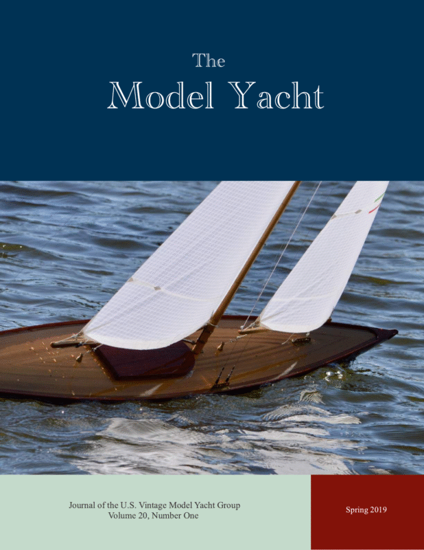
Spring 2019 Summer 2018 The Model Yacht The Model Yacht is published three times per year by the US Vintage Model Yacht Group. Copyright 1998 to 2019 by the USVMYG. Reproduction for noncommercial purposes permitted; all other rights reserved. Other copyrights are maintained by the original holders, and such material is used here under the fair use provisions of the relevant copyright acts for nonprofit research and educational purposes. The Layline President’s Message The US VMYG has a lot going on as can be seen in the issue of The Model Yacht. Make sure you take a look at the events list and all of the activities related to model yachting. Definition: A layline is a straight line (or bearing) extending from the next mark to indicate the course a boat should be able to sail on the one tack in order to pass to the windward side ofthe mark. (vsk. wikia. com/wiki/Layline) Editorial Address: John Stoudt 309 Sundance Drive Chester Springs, PA 19425 jstoudt309@gmail.com On the Cover: Domenick Bonanno’s new Traditional Marblehead, built by Harry Mote. Both are members of the Marbleheaders of Spring Lake Radio Control Model Yacht Club. Photo by Judy Bonanno. I would like to take a minute to discuss the work that has been going into preparing the issues of our newsletter, hereafter referred to as a journal. Our “newsletter” has not been a newsletter for a long time—it is something more than that. There are a handful of individuals who are preparing the journal. It is taking this group in the neighborhood of 250 hours to prepare each edition of our journal. Given this information we have to cut back to give our team some of their life back. Membership Renewals: The annual membership fee will be due and should be renewed with the publication of the first issue of the calendar year (this issue). Please reference the “Membership” form on pg.34 for dues amounts. And please use that form to complete your membership renewal. As a team we have been discussing ways to streamline the process. At this juncture the editorial team intends to: ● Continue to maintain a professional looking periodical. ● Maintain a flow of quality articles by well qualified individuals. ● Cut back the magazine to one of 32-36 pages not the 44 you have been receiving in 2018. Content is not an issue at this time. There is plenty out there. If you see something interesting pass on the information regarding the author and the content to me and/or Jeff Beck. If you have something to share, write it up. Do not be bashful because you don’t think you are a writer. We will help editorially. And please send high resolution photos that leave open space around the subject matter so that we can crop the photo to best fit the page. 1
Spring 2019 Summer 2018 The Model Yacht Inside Leadership Team……………..i The Layline…………………….1 Barnacles….5, 11, 15, 21, 29 Membership Renewal………1 Event Schedule……………….3 2019 National Regatta……..4 NOR: Freesail Marblehead Championship…………………5 Woods Hole Show…………..6 2018 US VMYG National Regatta…………………………..8 “Classic” Marblehead…….12 Make A Boom Vang………16 Schooner Rule Change…..18 Bending Wood Pt.3………..19 Scale Models Pt.2………….22 Corrections…………………..28 US VMYG Clothing……..29 We have a fine group of authors writing for us. Keep writing. Everything will get included in the journal. The reduction in the length of the journal may cause a delay in when an article appears. If an article is not in the next issue it will appear in an upcoming one. You can count on it. We are also using an electronic bulletin. It will go out from time-to-time. The purpose of this is to send information out between journals when we have it available. The information may be timely or important. This is one item mentioned in our survey, so we are trying it out now. 2019 celebrates the 25th anniversary of the United States Vintage Model Yacht Group. In conjunction with our anniversary, the Vintage National Regattas will be held in Honey Brook, PA, at the Tel Hai Camp and Retreat Center. Sponsored by the Chester Springs Model Yacht Club, it is scheduled for September 26–29, 2019. See the article later in this issue. The US VMYG has worked with Corporate Casuals to set up an apparel page featuring a clothing line with our logo embroidered on each piece. As an option you may have an anniversary note included under the logo to commemorate our 25th anniversary year. Look for more information in this issue. Issue 197 of the AMYA Model Yachting magazine will feature the US VMYG. We have put together quite a list of articles that will be submitted to the editorial staff of the magazine. These articles include: a President’s Message, a History of the US VMYG, Model Yachting Historical Milestones, Reward Sportsmanship, What Kind of Marblehead Is That?, Operation Layline, The Boats We Sail, Early Sailing Venues, Everything Old is New Again!, Early Building Techniques, Barnacles, Before Remote Control, and Early Pond Sailors. We have a great group of authors who have contributed to this edition of the magazine. If you are not a member of the AMYA you will want to join to get this feature issue. Chevrons are given to skippers who place in the vintage national events. AMYA has been providing them to us for the past few years, but they will no longer do that for the vintage group. Therefore, we will be providing our own “chevrons” to the winning skippers and their boats. We are going to provide our own distinctive design as shown. Construction Classes……..30 Resources…………………….32 Boat Registration………….33 Membership Form………..34 Be of good cheer and may the wind be in your sails. 2
Spring 2019 Summer 2018 The Model Yacht Event Schedule October 18, 2018 (opens) through 2-19………….Lighter, Stronger, Faster: The Herreshoff Legacy MIT Museum , 265 Massachusetts Avenue, Cambridge, MA 02139 April 13 – 14, 2019………………….Woods Hole Model Boat Show, Woods Hole, Massachusetts More information will be made available on the following website as it is finalized: www.woodsholemuseum.org/ April 27, 2019…………………………Vintage Invitational, Conservatory Waters, Central Park, New York, NY Hosted by the Central Park Model Yacht Club. WoodenBoat School Class July 7 – 14, 2019…………………….. Model Yacht Restoration (John Stoudt) WoodenBoat School, Brooklin, ME https://www.thewoodenboatschool.com/ WoodenBoat School Class September 15-21……………………..Build Your Own Plank Constructed Pond Yacht (Bruce Richter) WoodenBoat School, Brooklin, ME https://www.thewoodenboatschool.com/ September 21, 2019…………………..Free Sail Marblehead National Regatta, Spreckels Lake, San Francisco Hosted by the San Francisco Model Yacht Club. September 26–29, 2019……………. 2019 US VMYG National Championship Regatta. Tel Hai Camp and Retreat, Honey Brook, PA Hosted by the Chester Springs Model Yacht Club. October 19, 2019………………………Bill Bithell Cup (Vintage Marblehead Event) Redd’s Pond, Marblehead, MA October 20, 2019………………………Chowder Cup. Redd’s Pond, Marblehead, MA NOTES: • The US VMYG would like to identify and post the dates of events as soon as possible. If you are interested in hosting one of these events please contact Nick Mortgu at mortgu@comcast.net or (609) 820-0509. • The US VMYG encourages regional vintage events as well. Give it a go, get like minded individuals together and lets us know about it. We will publicize the event. • Watch our website for additions and changes to this schedule: http: //www.usvmyg.org/ • If you are aware of other noteworthy events lets us know so we can post them. 3
The Model Yacht Spring 2019 Summer 2018 Announcing 2019 National Championship Regatta The US VMYG and the Chester Springs Model Yacht Club (CSMYC) are proud to announce the celebration of the 25th anniversary of the US VMYG with the 2019 National Championship Regatta to be held on September 26–29 2019. The goals of the regatta schedule are to minimize travel costs, to maximize sailing time in each class and to accommodate skipper participation in conflicting events. The schedule may be modified at the discretion of the Regatta Committee based on fleet registrations, weather, and general sailing conditions. Thursday, September 26, 2019 Afternoon – Skipjack/Unrestricted Model Friday, September 27, 2019 Morning: Schooner/International A Boat Afternoon: Vintage 36/600, picnic Saturday, September 28, 2019 Morning: Vintage 36/600 Afternoon: Vintage Marblehead, dinner Sunday, September 29, 2019 Morning: Vintage Marblehead A spouses’ program is being arranged for Friday and Saturday (9:00 to 4:00) to Winterthur Museum/Gardens and Longwood Gardens on a costs bases with CSMYC spouses driving. The sailing location is Tel Hai Camp and Retreat Center, 1101 Beaver Dam Road, Honey Brook, PA 19344. This location can be accessed from either the Downingtown (Exit 312) or Morgantown (Exit 298) interchanges of the Pennsylvania Turnpike. Skippers of R/C Vintage Marbleheads, Vintage 36/600s, Schooners, Skipjacks, Unrestricted Boats, International A Boats, and other vintage model yachts are invited to participate. Membership in the US Vintage Model Yacht Group is required and the American Model Yachting Association is encouraged. Racing will be governed by the current Racing Rules of Sailing 2010 (RRS), as modified by Appendix E and the Regatta Sailing Instructions. The racing rules for all sanctioned classes as posted on the US VMYG website (usvmyg.org) will be followed. There are many hotels and restaurants in the Exton and Lionville, PA area. A Google search will produce many places to stay and eat. If you have questions, please feel free to contact the regatta coordinator. Eligible boats and skippers are entered upon receipt of completed Entry Form and entry fee. The entry fee ($60.00 for the first model yacht and $20.00 for each additional model yacht) covers trophies, on-site refreshments, a commemorative tee shirt, and lunch for skippers on each full day of sailing. There will be a mid-regatta dinner party at local restaurant on a per person cost and a regatta picnic. Lunch will be made available to skippers each full day of racing and is available to purchase for guests. The Notice of Race will be available on or before April 1, 2019. Information will be available in the US VMYG and the CSMYG websites on or before that date. More information can be found ● on the Chester Springs Model Yacht Club website:https://sites.google.com/site/csmyclub/ ● on the United States Vintage Model Yacht Group website: https://usvmyg.org/ ● or from John Stoudt (regatta coordinator) at 610-316-8695 or jstoudt309@gmail.com The entry form and fee are due on or before September 1, 2019. 4
The Model Yacht Spring 2019 Summer 2018 NOR Freesail Marblehead National Regatta By Colleen Stobbe, Commodore, SFMYC The San Francisco Model Yacht Club (SFMYC) is sponsoring a Freesail M Class Nationals, September 21, 2019, 1:00 pm at Spreckels Lake, Fulton Street and 36th Avenue, in Golden Gate Park, San Francisco, CA. There will be opportunity for practice the afternoon of Friday, September 20, 2019. No registration fee is required. 1. Going to the “Main Menu” on the left and about half way down clicking on “Sail Squadron” 2. Scrolling down to the list of classes at the bottom and clicking on “M Class”, 3. Scrolling down and clicking on the link entitled “M-class rating rules (pdf)”. 4. In the M-class rating rules (pdf) the BOLD text indicates the specific rules for Spreckels Lake. The SFMYC has developed M Class rating rules specifically for Freesail M Class boats on Spreckels Lake. In order to participate in Freesail M Class Nationals your boat will need to conform to the M Class rating rules designed for Spreckels Lake. The rules can be found on our website, www.sfmyc.org, and by: We welcome Freesail M sailors to join us in September for great camaraderie among freesailors and very fine competition on Spreckels Lake! Please contact SFMYC Freesail Squadron Officer, Dave Misunas, davemisunas@sbcglobal.net, no later than September 7, 2019, if you wish to participate or have questions. Barnacles worth checking out Battery Checker—A battery checker is a great tool to have in your tool box. It is a quick, clever, and convenient device for analyzing your batteries. The checker shows at a glance the remaining capacity in your battery pack, cell balance, cell voltages, and gap. This device provides the information and tools you need to maintain top performance and reliability from your batteries and to avoid costly mistakes. One example is the Hyperion Sentry EOS V3. Servo Checker—An R/C Servo Tester allows you to set up, test, and center up to 3 servos at one time. Featuring a Manual, Neutral, and Auto button, you can quickly move from one function to the next with a quick press of your finger. It is a great tool to verify the functionality of and to set up your servos. 5
The Model Yacht Spring 2019 Summer 2018 Woods Hole Model Boat Show April 13 & 14, 2019 Author Jennifer Gaines Sometimes, visitors are allowed to take the controls and try some “twothumbed sailing”. In the very first show, a former jeweler from Camden, ME exhibited his new model yacht replete with exquisite detail, including fittings made of gold. By contrast, at one of the most recent shows, John Fries of Fries Sail Design Company of Connecticut raced two of his carbon fiber monohull racing yachts, fitted out with Kevlar sails similar to the full-scaled sails he produced for an America’s Cup challenger. Over the course of its more than 20 years’ existence, the Woods Hole Model Boat Show, sponsored by the Woods Hole Historical Museum, has become a festival of model boating. At its core has always been a display by the US VMYG and races run by the AMYA, but over the years, a variety of displays, talks, and activities have been added that appeal to all levels and ages of participants and visitors. The show stretches the length of the main street in Woods Hole, an easy walk, with static models exhibited in six buildings, some owned by the world famous Woods Institution and Marine Biological Laboratory, plus two outdoor locations. This main road, Water Street, is wedged between the waters of Great Harbor where the ferries depart for Martha’s Vineyard, and the protected water of Eel Pond. The races are held just across the road from the main exhibit hall on Eel Pond. The races include the R/C “over 40 inch” Vintage Marbleheads and Wheelers and the “under 40 inch” class, which always includes a fleet of Solings from Martha’s Vineyard. All comers are welcome; slots for demonstration sails are always included. Conveniently located along the route between exhibit halls are a coffee shop and a bakery–sandwich shop, and a few steps away, several delicious and upscale restaurants which offer discounts to people attending the show. Photographer John Stoudt. 6
The Model Yacht Spring 2019 Summer 2018 The event is fun for the visitors, allowing them to interact with the modelers and racers. The Museum sets up a pool in their front yard where kids can build and sail simple pond models, based on the Museum’s icon, the Woods Hole Spritsail Boat. Practical talks are always included such as how to build Plexiglas cases for models given by Ed Thieler of Maryland and building scratch-built traditional sailing craft by John Stoudt of Pennsylvania. Modelers usually spend most of their time with their models, talking with the public and other modelers, creating an aura of great friendliness and goodwill. Alex Bellinger, creator of exquisitely detailed ships-in-bottles, always shares a table with local folk-artist and ship-in-bottle maker Gerald Ross who delights in showing the public the mysteries of their craft. They have been joined by Tony Colton, who builds most of his models in light bulbs, even to the extent of building the Nina, the Pinta, and the Santa Maria in matching bulbs. This year the talks will include Rib Napier speaking about his recent project researching and building a model of an 1877 full-rigged merchant ship, John Stoudt speaking about historical milestones in model yachting, and James Norton from Maine, telling the story of his building a model of St. Columba’s leather curragh, which dates to the 7th century. He built it in the traditional fashion, right down to the leather hides. Also, interesting, he builds all his human figures from scratch, from epoxy clay over wire armatures, and a great job he does! There are several commercial exhibitors in the Show, some selling kits and others selling completed craft. A popular “Dockyard Sale” has been added where people can sell their old, new, or unfinished boats, kits, and parts, all on consignment. Exhibitors are always treated well at this event. The Museum welcomes them into the village late Friday afternoon with a casual reception after they have set up their exhibits and again on Saturday after the successful first day of the show. Camaraderie abounds. Woods Hole Historical Museum Photo. Every show has included interesting talks, from the exquisite detail which Rob Napier showed in his restoration work on a 16th century vessel for Boston’s Museum of Fine Arts, to the bold education project started by Dick Baldwin who worked with school groups building his rugged 4-foot boats and setting them adrift in the Atlantic, tracing them with GPS, and occasionally retrieving one from the European coast. Usually an engineer from WHOI gives a presentation on some of their recent underwater “models” designed to capture information in the world’s oceans. The dates of the next Woods Hole Model Boat Show have been set to April 13 & 14, 2019. As usual, the Show will be held on Massachusetts’ Patriot’s Day weekend. Tickets are very reasonably priced for the two day show: $15, with children under five free, and older children $5. New participants are welcomed. More info and registration for exhibitors are available on their website www.woodsholemuseum.org. 7
The Model Yacht Author John Snow Photographer Judy Bonanno Spring 2019 Summer 2018 2018 US VMYG V36 & VM National Championships Sixteen skippers competed in the 24th annual US VMYG National Regatta on October 18–19, 2018 (Thursday and Friday) at historic Redd’s Pond, Marblehead, MA. These were part of the Mini-Race Week event that included the Marblehead Model Yacht Club’s Bithell VM Cup Regatta on October 20 (Saturday) and Chowder Race/Messenger Cup (Open) Regatta on October 21 (Sunday). The regattas were hosted by Marblehead MYC after a late venue change decision in May in close collaboration with the US VMYG. Activities featured Vintage 36 (36/600) and Vintage Marblehead (50/800) R/C models. The V36 and early VM Traditional (TR) designs cover the 1930–1945 Marblehead Class developmental period; the US VMYG’s High Flyer (HF) designs cover the 1946–1970 period. The V36 fleet was well represented. 8
The Model Yacht Spring 2019 Summer 2018 Volunteer appreciation awards were presented to those supporters plus Judy Bonanno for her two-day photo efforts. VMs taking advantage ofsteady winds. Harry Mote took top racing honors in V36 and VM TR design fleets through his superb sailing consistency, racing boats of his own design. Cliff Martin won in the VM HF design category racing 1960s era Magic Dragon model. Also noteworthy were the five skippers who competed in all 29 races: Dominick Bonanno, Rob Dutton, Harry Mote, Thom McLaughlin, and John Stoudt. Winds were mainly steady with gusts from the west– northwest Thursday and southwest on Friday. The winds accommodated a full pond-length racing course with both offset and gate marks. Skies were sunny with temperatures ranging from the 40s in the morning to upper 50s by midday. In total, there were 29 races including two throw-outs each for a seven-boat V36 fleet and the nine-boat VM fleet. Awards (crafted by Tod Johnstone of Mystic, CT) were presented to the top three skippers in each category: the V36 design and both VM TR and HF designs. Scorers were Rick Gates and Jerry Leach (from the Nashua Model Yacht Club) on Thursday with the addition of Sue Martin on Friday. They ably supported RD John Snow. Lunches were provided by Cheryl Emmons and Biff Martin. 9 RD John Snow (right) presents Harry Mote with one ofhis two 1st place race awards, this for his V36 win.
The Model Yacht ● Spring 2019 Summer 2018 2018 US VMYG V36 & VM National Championships Summary The Marshall Croft Sportsmanship Award was presented to John Stoudt for his extraordinary efforts as the new US VMYG President. This is a perpetual US VMYG non-racing sportsmanship trophy awarded based on a vote of peers (our “gray beards”). ● Marblehead Charter School students with teacher mentors joined us Thursday morning to learn about the history of the sport of model yachting at Redd’s Pond. They did this while conducting an onsite environmental study that included water quality testing. ● One unlucky skipper was Herb Dreher who ended his V36 racing day with an unexpected full immersion into Redd’s Pond’s waters. Classes Raced: V36 and VM Traditional and VM High Flyer Models Date: October 18–19, 2018 Location: Redd’s Pond, Marblehead, MA Host Club: Marblehead Model Yacht Club Entries: Vintage 36s, 7; Vintage Marbleheads, 9 Conditions: Gusty W 10/18 and Gusty SW 10/19; Partly Sunny 45–60o Races Complete: V36 Fleet, 13 (2 throw-outs); VM Fleet, 16 (2 throw-outs) Scoring: Low Point System Race Committee: Regatta Director, John Snow; Support; Rick Gates, Jerry Leach, and Sue Martin Food & Hydration: Cheryl Emmons, Biff Martin, and Rick Gates ● Another unlucky skipper was Cliff Martin who walked right off the edge on Friday during the the VM races to an unexpected full immersion of his own into Redd’s Pond’s waters. A much deserved “Volunteer Appreciation Award” presented to photographer Judy Bonanno by RD John Snow. 10
The Model Yacht Spring 2019 Summer 2018 Barnacle Miniature Electric Screwdriver – General Tools 500 Ultra Tech Power Precision Screwdriver. This small but precise screwdriver is the perfect tool for on-the-go repairs as well as working on electronics, small parts, and micro assemblies at home. It comes with six bits, runs on two AAA batteries, and at under $15 you can buy one for your travel case and one for the workbench. 11
The Model Yacht Spring 2019 Summer 2018 “Classic” In Search of the Author Ken Young When John Stoudt asked me to write an article describing the various divisions of the Marblehead Class for the AMYA magazine Model Yachting, I knew it would be a challenge. This was mainly because I knew nothing about the history of the boat. The most difficult of the divisions to describe was the “Classic”; that time period from about 1970 to the mid 1980s. As I did the research, I became fascinated with the developments the class went through. New technology (tank testing for model boats), new material, rule changes, and innovative designers lead to significant changes in the boat. But that’s the purpose of a developmental class. In 1930 Roy Clough, commodore of the Marblehead Model Yacht Club, proposed a new class of boats, the Marblehead 50/800, with a length of 50 in and 800 in2 of sail. With it being a developmental class, the design of the hull and rig changed over time with new technology and materials. Boats were originally free sailed, and still are. The introduction of radio control brought about many new developments. R/C Marbleheads have been differentiated into four divisions determined by design characteristics of a particular time period: Vintage Traditional (1930–1945), Vintage High Flyer (1945–1970), Classic (1971 through mid-1980s), and Modern (mid1980s through present). Marblehead Builder’s ads from the 1970s and 80s were interesting. You could rarely buy plans, but instead bought kits since there was more money in that. The ads also showed which boats were being pushed by various designers and boat shops. When new designs came out, sometimes only the top sailors could get them. If they proved successful they were made available to everybody. Rule changes in the early 1970s removed some of the restrictions that had been in place. Prognathous keels were no longer forbidden (No part of the bulb could extend beyond the leading edge of the keel). The requirement for 1-in garboard radius at the keel/fin joint was eliminated. This had been put in place to prevent movable keels and metal fins. Boats like the Littlejohn 50, Soling Marblehead, and Shadow had swept back keels, wide beams, shorter rigs, and large jibs. Rod Carr once said that the Littlejohn 50, designed by Sandy and Andy Littlejohn in California, looked like “a dough dish crossed with a punkin seed.” I have one. He’s right. But it’s fast. Aquilo profile. Doug Pederson’s Bingo and Ray Ozmun’s Aquilo both appeared about 1974. They were fairly typical of that period, but they did show the mix of designs. The Aquilo had a non-prognathous keel, while the Bingo did not. Bingo’s beam was 10 in, and the Aquilo’s was 13 in. Both had a draft of 15 in and displaced 15–16 lb. Yet both were competitive in 1976 ACCR. Bluff bows to increase waterline length became the signature look of the class. 12
The Model Yacht This period of the mid to late 1970s saw a real high point for the class. In the US, Marblehead registration was almost three times that of the next class (36/600) and was almost equal to the total of all other registered boats combined. So many skippers wanted to sail in the ACCR that there had to be qualifying regattas leading up to them. But it was also when complaints that M boats had become a “boat of the month” class. With so many new designs coming out people were buying one, if not multiple, new boats every year. Complaints were also starting that 10 AMYA classes was too many – 10! As an aside, unlike today, there were very few regattas in the South. Spring 2019 Summer 2018 Bingo’s 10 in beam. Aquilo’s 13 in beam. It’s at this point that geography seems to play a part in which boats did well. While most designs were sailed all over the country, the results from regattas would seem to indicate that Epics and Bingos were big on the west coast, Warrior and Warrior II on the east coast, and Magic Dragons in the Midwest. The late 1970s also saw taller rigs. Most mast heights had been about 72–77 in, but now we start to see main luffs at 80–82 in. Bingo profile. 13
The Model Yacht Spring 2019 Summer 2018 By this time, Mylar® sails had become the greatest things since pockets. Sailmakers were experimenting with different thicknesses, combination “sandwiches” of layers, and reinforcing string in the material. The sails became so important that regatta results would include not only the design of the boat, but also who made the sails. example, the Kisutch, designed by Bob Stearne in 1978, was a very successful boat. Bob owned Bob’s Boatyard, and in an ad in the AMYA quarterly in 1986 he was describing two new boat designs he had for sale. Almost as an afterthought the ad said “We still offer the Kisutch as a low tech, inexpensive Marblehead since some clubs desire to follow the approach.” Keels became longer so that less weight could be used. It took a while for keels to get much longer than 17 in because designers were having trouble eliminating what they called “flutter”. The keel would vibrate side to side. Carbon fiber, and the shape of the fin itself, helped solve the problem. They also realized, though, that in light air long keels are slow, and hitting the bottom of a shallow pond is even slower, so boats came with more than one keel. In 1982 the Bone arrives, which I consider to be the beginning of the Modern boat designs. It was designed specifically to be built of Kevlar®. But it had to be kept in a humidity controlled environment or it would warp. There were 15 designs of Bone, with considerable tank testing, but it garnered only mixed reviews: good off the wind but not so good to windward. In 1980 we see boats like Toad show up with more rocker in the stern—there is more freeboard in the bow than in the stern. This was to help prevent submarining downwind with the taller rigs. At this point there seems to be an explosion of new boat designs, and we start to see the old stalwarts like Bingo and Aquilo not showing up in results as often. The question is, did they get slower, or were skippers just replacing them with hot new designs? For Fiberglass remained the hull material of choice. When Chuck Black obtained the molds for Toad and Spot in 1984 you had a choice of Kevlar, carbon fiber, or fiberglass. While Kevlar and carbon fiber were the lighter materials, fiberglass was definitely cheaper. We don’t see swing rigs until after the World Championships in Germany in 1988 when Graham Bantock had them on two boats. Again, in my opinion, swing rigs are more modern. Black Watch, a Classic Marblehead with a prognathous keel. 14
The Model Yacht Spring 2019 Summer 2018 Bone, an early Modern Marblehead. Acknowledgments Unfortunately we start to see the falloff in participation in major regattas in the late 1980s. The complaint was that in order to be competitive at the upper levels, the boats had become too expensive. Almost tongue in cheek, Ray Ozmun said the boats were getting so fast you had to run to keep up with them. If so, that might discourage a certain segment of skippers. Boats like Magic Dragons, Bingos, Epics, etc continued to be raced successfully, but fell from the top tier of major regattas. I had a great deal of help with this project. Ed Wolfe is an encyclopedia of Marblehead history. Biff Martin and Standley Goodwin have been involved since the beginning. Graham Reeves in the UK wrote a book on the history of Marbleheads and shared parts of that with me. One of my best sources was my sailing buddy Jeff Gros, who showed up on my doorstep with 57 editions of the AMYA Quarterly magazine published from 1974–1990. These were priceless! I could see Annual Class Championship Regatta (ACCR) results, as well as many other regattas. There were also many critiques of various boat designs. One thing became clear. Just like now, the good guys did well no matter what they sailed. The thumbs on the sticks seemed to have more to do with success than the design of the boat. The Classic period saw very progressive thinking and creative uses of technology. The boats are still incredibly fun to sail. So if you have one of these Classic boats, dust it off, get it in the water, and reacquaint yourself with the fun you had the first time you got it wet. Barnacle The Boat Yard—Do not forget to check out the US VMYG Boat Yard. We are providing information on vintage model yachts for sale. All arrangements are between the seller and buyer. Go to: https://usvmyg.org/category/boat-yard/ 15
The Model Yacht Spring 2019 Summer 2018 How To Make A Boom Vang Author Ivor Walton This article describes how to make a boom vang with a turnbuckle. It can be whatever length is needed to fit your boat and have either a brass or aluminum finish. Fig. 1 shows two completed vangs: one brass and one aluminum. The dimensions given here are for a 6-in vang. slightly oversize and then trim to the correct length after gluing. A bench disk sander with a 90° sliding guide is a good tool for squaring tube ends. De-burr the inside ends of finished tubes with a sharp drill. Roughen gluing surfaces with a file or sandpaper and use slightly thickened epoxy for gluing. Materials for a 6-in aluminum vang Fig. 2 shows all the parts for the vang body: 2 ¾ in of 3/16” tube, 2 ⅜ in of 5/32” tube, ½ in of left-hand (L/H) threaded 1/8” tube, a turnbuckle, and a clevis. I use a jig to hold a 12-in length of 1/8” tube while tapping the 4-40 L/H thread and then cut off the ½in threaded piece. The jig is made from two pieces of one-by lumber, each 1 ½ in square. Clamp them together to make a cube and then drill a 7/64-in hole vertically down the line of the join, at the center of one side. When you unclamp the two pieces there should be a semi-cylindrical Directions for a 6-inch aluminum vang 1/8”, 5/32”, 3/16” diameter nested aluminum tubing. (Each tube fits exactly into the next size. Hobby shops and hardware stores carry these tubes in 12-in lengths.) ● 1/16” sheet aluminum ● A Dubro 4-40 turnbuckle ● Two 4-40 threaded steel clevises from Great Planes ● 5-min epoxy with micro-balloon filler ● Two 4-40 Left Hand taps: a starting tap and a bottoming tap ● I use either a Dremel rotary tool with a cutoff wheel or, better yet, a Drillmaster 2-in bench-top cutoff saw to cut the tubing. Both tools are very effective for cutting small tubes because they cut without distorting the tube. It’s better to cut the lengths Fig. 2. Parts for the vang body. 16
The Model Yacht Spring 2019 Summer 2018 Turning Wheel groove down the middle of each piece (see Fig. 3). Clamp the two pieces together in a vise with the 1/8” tube in the grooves, and it will be held securely so that you can tap the L/H thread. This is not a simple process, but it can be done with a little care and patience. Fig. 4 shows the parts needed: the turnbuckle, a ⅝ in diameter aluminum disk with a 5/32 in hole at the center, a ⅜ in length of 5/32” aluminum tube, and two 5/32 in long pieces of 3/16” aluminum tube. Cut and file the ⅝in disk from 1/16” aluminum sheet and drill a 5/32in hole at the center. The ⅝ in dimension can be smaller or larger depending on personal taste. Force the ⅜-in piece of 5/32” aluminum tube over the hexagonal section at the center of the turnbuckle so that it is equally spaced on either side of the turnbuckle center. I made a tool for doing this from Fig. 3. Jig for holding a tube while cutting the thread. It is important to get a full half inch of thread. You will need a bottoming tap in addition to a starting tap in order to achieve that. Epoxy the ½-in threaded piece into the end of the 2 ⅜ in length of 5/32” tube, being careful not to get glue on the threads. Then epoxy this assembly into the 2 ¾ in length of 3/16” tube. All three tubes should be flush at the threaded end. There will be a ⅜-in long opening at the other end to accept a clevis. Fig. 4. Parts for the turning wheel. a short length of ⅜-in hard wooden dowel with a 7/64 in hole down the middle. Place the aluminum tube onto the turnbuckle, followed by the dowel, and hammer the tube over the hexagon (see Fig. 5). Before proceeding further, make sure the turnbuckle turns freely all the way through the threaded piece. Now epoxy a clevis into the open end of the main body. Be sure to roughen the surface of the clevis thoroughly because the Great Planes clevis is chrome-plated. You can even file some grooves in it to help the epoxy get a good hold. Screw in the turnbuckle, add a clevis to the other end, and you have a fully functional boom vang. However, I like to go one step further and add a turning wheel as follows. Fig. 5: Dowel for driving the tube over the turnbuckle hexagon. 17
The Model Yacht Spring 2019 Summer 2018 Other Options This process expands the aluminum tube slightly, and it must then be filed back down to the original 5/32 in diameter so that the disk fits over it. For a brass vang, just substitute brass tubing for the aluminum tubing. The only exception is the ⅜-in piece for the wheel assembly. Stay with aluminum for that piece because it is not possible to force a brass tube over the hexagonal section on the turnbuckle. If you want an all-brass look, you can use Sullivan brass clevises instead of the steel ones from Great Planes. However, the Sullivan clevises are shorter and will give less total vang travel than the Great Planes clevises (1 in versus 1 ½ in). If you prefer a ball link at the mast end, epoxy a 7/32” tube over the main body and use a Dubro 2-56 swivel ball link instead of a clevis. It will fit exactly into the 7/32” tube. Now cut two pieces of 3/16” tube 5/32 in long. These will hold the disk in place. Put a slight countersink on both sides of the hole in the disk and on the end of each small tube that will butt up against the disk. These countersinks will provide more gluing surface for the epoxy. Now epoxy the three pieces together on the tube at the center of the turnbuckle to complete the wheel. Polish all the aluminum surfaces with very fine steel wool, and the boom vang is complete. Fig.6. The finished wheel. Schooner Rule Change—Follow-up Author Charlie Blume In the Fall 2018 issue of The Model Yacht, the question of changing the Schooner class rules to allow scale schooner models with extra draft to be still considered “scale” was presented. Since response has been minimal (two for, two against), and there does not seem to be any real pressure to change the rule, the rule will stand. Full disclosure, I am one of the two against. In my opinion “schooner models” are defined by their rigging. Scale models are built to scale. No one has ever been turned away from racing. 18
The Model Yacht Spring 2019 Summer 2018 W g o n o i d d n e B Part 3 Author and photographer John Stoudt In the last article in the series I discussed making the mold for bending items for use on a model yacht. This article describes using a mold to assemble a curved shape— in this case an ovalshaped hatch cover. I chose the smallest “cooking chamber” and added aqueous ammonia to the container to within two inches of the top. The wood strips were then placed in the container and the lid secured. The wood was allowed to cook for 24 hours. The first things you must do is choose your wood. Mahogany veneer was chosen for this application because mahogany is easy to bend, and the veneer is a nice thickness. I purchased a package of veneer from Woodcraft that included three 12×12-in pieces of Philippine mahogany. I decided to use the hatch opening (cowling) on the boat as the mold in this application. This cowling sticks up ~½ in above the deck and could be accessed easily with the clamps necessary to hold everything in place. A control band of aluminum would not be necessary in this application unlike with the mold described in Part 2. Cover the area around the hatch on the boat completely with masking tape. This keeps the glued-up assembly from sticking to the hatch cowling and deck while the glue is setting. Cut Veneer With Utility Knife. I calculated how many pieces I would need to construct the edge of the hatch cover using three layers of veneer. I added two pieces to the count, making it 11 pieces total. The veneer was cut into ¾-in strips using a utility knife on a cutting matt with a metal straight edge. Hold the straight edge tight to avoid slipping. Tape Area. 19
The Model Yacht Spring 2019 Summer 2018 Remove the veneer strips from the chamber when they are ready and wrap them around the hatch with some overlap and without cutting them. Consider the location of each butt joint: keep the joints away from the harshest curves on the oval. Wrap the strips around the cowling and clamp it in place with ¾-in spring clamps. Pay attention to the tightness of the assembly as the clamps are placed. Allow the assembly to dry overnight. Wrap the strips around the cowling and clamp it in place with ¾-in spring clamps. Pay attention to the tightness of the assembly as the clamps are placed. Allow the assembly to dry overnight. Begin to assemble the first layer of veneer. Select the pieces of veneer that will form the first inside ring of the of the hatch frame. Cut the ends of the first piece square, keeping the joints away from the most severe curves of the shape. Clamp this piece into place with a few clamps. A good pair of sharp scissors works well for this. Cut the ends of the next piece of veneer square and clamp it into place butting one edge against the edge of the first piece. Use only a few clamps. The last piece of veneer for the first ring should be cut to fit in the opening left by the first two pieces of the first ring of the assembly. The second ring needs to be cut and fit around the first ring. Make sure you stagger the joints—keep the joints at least one inch apart. Staggering the joints ensures the integrity and of the final assembly. Clamp this ring in place to the first ring and the cowling using a few clamps to hold everything in place. Repeat this process with the third and last ring. You now have a dry assembled hatch frame clamped to the hatch opening cowling secured with enough clamps to give you an idea of the final assemble. Now take it all apart and carefully lay all of the pieces in the relative relationship on a the workbench. Re-clamp the first ring onto cowling with a few clamps. Take one piece of the second ring and apply a generous amount of glue to the inside surface. Dry Assembly Before Gluing. When the strips have dried completely, remove the clamps. Arrange the bent strips on a flat surface in their relative position to each other— the way they came off of the “mold”. At this point the strips will hold the relative shape that was obtained through the bending process. Glue Applied to Veneer Strip. I use TiteBond II for this application. Remove enough clamps to apply this piece in location to the first ring. Make sure the top edges align. Replace the clamps. Repeat this process with the remaining 20
The Model Yacht Spring 2019 Summer 2018 pieces of the second ring. You only need enough clamps to hold the assembly in its general position at this point. Make sure that you have good glue coverage at the butt joints. Repeat this process for the third and last ring. Clamp the entire assembly with clamps placed around the entire assembly as close together as possible. This will help to give your assembly good shape and ensure joint integrity. When the glue has dried completely, remove the clamps and carefully pry the hatch cover frame from the cowling. This assembly is very strong at this point. It will be tight and may be sticking to the tape. Remove the tape from the hatch rim and the deck/cowling. Glued Assembly Prior to Final Clamps Being Added. 3. I wanted to show how this process could be used to form a completely round, in this case, elliptical shape. The construction of the hatch cover will be discussed in part 4. Sources Author’s Note: You may wonder why I did not use the mold described in part 2 of this series. I used this method for three reasons: 1. I was restoring a classic Marblehead that had this unique elliptical hatch opening, 2. I thought I would demonstrate using a shape on a boat for the mold. ¾-in spring clamps – 20-Piece ¾-in (19 mm) and 1in (25 mm) Jaw Open Steel Spring Clamp Set – they can be found on Amazon. Veneer Package – Woodcraft – Mahogany Veneer 1/16-in thick 3-ft2 pack. TiteBond II – Available at any hardware or large box store. Barnacles For centuries, Asians have been racing model yachts—Check out this link to a video of traditional sailing models in Asia called Malay Jongs: https://tinyurl.com/y4nw9nsa Mystic Seaport Museum—At a meeting with Paul O’Pecko, Vice President of Research Collections, he showed me much of the material they have collected on pond models. This includes a Nat Herreshoff Marblehead with a wishbone rig and a Gus Lassel Marblehead. Look for more information about these boats in the future. —John Stoudt. 21
The Model Yacht The Model Yacht Spring 2019 Planning and Building Scale Models that Sail Part 2 : Design Calculations Author and Photographer John Henderson We will begin with displacement calculations. A much-reduced set of lines drawings for the original Rainbow is shown in Fig. 1. In Part 1 of this series, we went through some “quick and dirty” calculations that enabled us to choose a suitable size and weight for a semi-scale model that can be expected to sail well. The example we used was a 1:23 model of the J-Class yacht Rainbow, and we will continue to use that example in the rest of this series. We will now undertake some more detailed and a bit more extensive calculations to try to get the boat right as built, requiring minimum modifications and fixes after the fact. Not only will this give us a model that is better-constructed, but the radio gear, the ballast, and the sail controls should be more accessible, meaning that they are likely to work better and be more easily and successfully maintained. Fig. 1. In Part 1 of this series, we used a very much simplified set of lines to explain the roles of the profile, sections, and plan views. The lines drawings for the full-size Rainbow in Fig. 1 are typical of the considerably greater complexity of drawings for an actual boat. Note that the sections drawing has been superimposed on the profile. As discussed previously, we will probably want our model to have a deeper keel, either by adding a Rainbow lines drawings. 22
The Model Yacht Spring 2019 Summer 2018 fin-and-bulb or by fairing in some greater depth to the keel profile. For my own 1:23 version of Rainbow, I opted to make the keel about 1.5 in deeper. The easiest way to visualize this (and preserve a pretty profile) is to start by modifying the profile drawing —but note that this means that the sections drawings must also be modified for all sections affected by deepening the keel profile. We would like to preserve the waterline location (for the sake of scale appearance when afloat), but we have added volume below the waterline, which will change the displacement from our “quick and dirty” estimate. online, but a formulation that is more specific to boat designing can be found in books like Skene’s Elements ofYacht Design . It requires no math skills beyond straightforward arithmetic, but it is timeconsuming. It is probably an afternoon of careful work, and you will not be pleased if you discover that you’ve made a mistake part way through. You begin by measuring the area below the waterline of each half-section on the sections plan of the lines drawings. Simpson’s Rule requires that the sections be evenly spaced and that there be an even number of sections. This explains the numbering of the sections—section #0 is usually located at the forward end of the waterline (not at the bow), and spacing is such that an even-numbered section is located at the aft end of the waterline (#20 in the example I will present). Note that sections in the bow and stern overhangs, which are outside the waterline, are not used in the displacement calculation. Also, it is common practice for models to have a rudder that is larger than scale size for better handling and control. I followed this practice and made the rudder about 50% larger in area than scale. This also changes the underwater volume. These changes to the underbody make it desirable to do a new calculation of the displacement. Additionally, I think we should do a more accurate calculation (than the simple division by the cube of the scale factor that we used for quick estimates in Part 1) because that estimate was based on some published weight, which is often inaccurate. Calculating Displacement Measuring the areas is the hard part. If you have access to a device called a planimeter, you can trace around each half-section and read the area directly (you probably should do it a couple of times and average the results). I don’t have such a device, so I used a more tedious method: get some engineering graph paper with a reasonably fine grid of squares or make such a grid yourself. Lay this grid of squares over the sections drawings and count the number of squares in each half-section. Since you know the area of each square on your grid, you can compute the area of each section in units of square inches. Be careful, and check each measurement against its neighboring sections for plausibility. In general, Simpson’s Rule is a method of numeric integration (as in calculus). You can look it up This tabulation of the (below-the-waterline) halfarea of each section is the input data to the Simpson’s Rule calculation. I will review the method of displacement calculation that uses Simpson’s Rule. This is a traditional method that may seem tedious and quaint for folks with access to computer-aided design tools, but it can be done with measuring tools available to everyone and it gives appreciation for the traditional design process. Think “vintage”. 23
The Model Yacht Spring 2019 Summer 2018 Displacement = 2 x [1/3] x [sum of functions of half-areas] x [inverted scale] x [station spacing interval] x 0.037 To perform the calculation, you will construct a table as shown in Table 1 below. The first column is the section number, from 0 to 20 in our example. ● The second column is the area in square inches of each half-section from the lines drawing, which is what you just measured with the graph paper. ● The third column shows “Simpson’s Multipliers”, which are 1, 2, or 4 in the pattern shown, always starting and ending with 1. ● The fourth column, labeled “Functions” is the result of multiplying each section half-area by its corresponding Multiplier. ● We’ll talk about the fifth column later when we discuss the Longitudinal Center of Buoyancy (LCB). ● where: ● The factor of “2” is because we only measured the half-areas. ● The factor of 1/3 is per Simpson. ● “Inverted scale” only pertains if we are using drawings that are not full size (as we would for a full-size boat). In our case, using plans that are the size of the actual model, this factor is 1. ● “0.037” is the density of salt water in pounds per cubic inch, because we measured area in square inches. (Salt water density is usually stated as 64 pounds per cubic foot.) ● The calculated units of Displacement are pounds. The data and associated arithmetic for our 1:23 scale Rainbow example is shown in Table 1. And now, the formula for displacement according to Simpson’s Rule: 24
The Model Yacht Spring 2019 Summer 2018 Inserting the sum of Simpson’s Functions into the equation above, and noting that the station spacing on my 1:23 Rainbow example is 2 and 5/32 in (2.156 in) gives right, but, basically, we want to get the center of gravity of the ballast in the right place fore-and-aft. Otherwise the boat will trim bow-up or bow-down. So where must the boat’s center of gravity be located? It must be at the Longitudinal Center of Buoyancy (LCB), which is determined by the shape of the boat’s underbody (the submerged portion of the hull). Calculating the LCB is the purpose of the 5th column in Table 1, called “Moments for LCB”. Displacement = 26.3 lb which is reasonable given the “quick and dirty” estimate of 25.5 lb and noting that we increased the volume of the underbody by adding draft and increasing the size of the rudder. Note that a model of this weight should settle exactly to the waterline. We may want to make the model a bit lighter so that some bottom paint shows at rest. The numbers in the LCB Moments column are generated by multiplying Simpson’s Functions (the 4th column) by the number of the station (column #1). This essentially gives the “leverage” that the buoyancy of each station provides relative to station 0 (the forward end of the waterline). Those moments are summed, as given at the bottom of column 5. The sum of these moments is then divided by the sum of Simpson’s Functions, to give: In fact, we can calculate how much higher the model will float as a function of weight change. To do this, we first calculate the area of the plane of the waterline in square inches. (Using the plan view of the lines drawings, I did an approximate calculation for the area between each station at the waterline and summed those areas.) Multiplying this area by 1 in gives the volume of water that is 1 in thick in a plane the size of the waterline plane, and we get its weight by multiplying by the density of water (0.037 lb/in3). Sparing you the tedium of yet another table of numbers, I’ll give the result: approximately 3 lb per ¼-in immersion. This means that we can expose a bit of the bottom paint by shaving a couple of pounds off the weight. Or, more usefully and less cosmetically, it shows us the degree of flexibility we have to adjust ballast or control system weight. 5282.6 / 494.74 = 10.68 This means that the LCB is located 10.68 stations aft of station 0, which, for the station spacing in this example model, is 23.03 in. So, if we suspend the boat (in the air) from this point, we must arrange the ballast and other gear so that it balances level. Ballast has the dominant effect, but it would be good to locate the radio gear approximately (especially the battery and any big servos) and to place 1.5–2 lb at the mast location (calculated below) to simulate the rig weight. Calculating Longitudinal Center of Bouyancy and Center of Gravity Mast Location and Center of Effort On any reasonable sailing model, the dominant component of total weight is the ballast, and its location fore-and-aft is the major factor in locating the center of gravity of the whole boat. We might want to reserve a small percentage of the total ballast to make trim adjustments if we didn’t get the weight estimates of the rig or the radio quite If we make changes to either the rig or the underbody—and we have made the case for such changes in all of the previous discussions—then we need to re-visit the helm balance. When sailing on a reasonably close-hauled course, the boat should want to continue sailing in a straight line or—as I prefer because it is what I like in a full-size boat— 25
The Model Yacht Spring 2019 Summer 2018 With reference to Fig. 2: 1. Create an accurate drawing of the sail plan, including main and jib. This could be much smaller than your actual model, but it must be scaled from your model plans. 2. For each sail, draw lines from each corner (tack, clew, head) to the center of the opposite edge of the sail. The CE for that sail is located where these lines meet. 3. The CE for the entire sail plan is located on a line that joins the individual Centers of Effort, and its exact location must be “weighted” by the relative areas of the two sails. Here we’ll compute the distance by which the total CE is aft of the mast, which is: the boat should have a slight tendency to round up to weather. This is called “weather helm”. The boat should never want to head off away from the wind (called “lee helm”) because correcting this with the rudder introduces drag and a sailing angle change that actually reduce progress to windward. Proper helm balance requires the right relationship between the Center of Effort of the sail plan and the Center of Lateral Resistance of the hull underbody. The locations of both of these Centers change dynamically with sail trim, sailing angle, and heel angle, but those dynamic changes are beyond the scope of this article. We can, however, get pretty close by considering the problem statically, and I think this is the traditional design technique. Both Centers can be thought of as the single points where all of the respective forces of wind on the sails and water on the underbody could be centered—analogous to the Center of Gravity for weight. {[area of main] x [dist. of its CE aft of mast] – [area of jib] x [dist. of its CE forward of mast]} / {total sail area} There is a simple and non-technical procedure for locating the Center of Lateral Resistance (CLR) of the underbody: 1. Trace the area of the profile view that is below the waterline onto a piece of light and stiff material, like cardboard. 2. Balance this cardboard cutout on a ruler edge that is perpendicular to the waterline. The fore-aft CLR is at this balance point. (You only need the fore-aft location for this exercise: the vertical location does not matter.) If you are planning to add a fin-and-bulb keel, then the CLR of this added keel should be at about the same position as the original CLR. Locating the Center of Effort (CE) of the sail plan is only slightly more complicated. Fig. 2. Sail plan drawing, showing CE measurement lines. 26
The Model Yacht Spring 2019 Summer 2018 To counteract this force turning the boat to weather too strongly, we can move the CE of the sail plan forward, which would tend to steer the boat to leeward. The problem is: “How much forward and at what heel angle do we make this calculation?” Hence the “trickiness” and uncertainty. I suggest that the mast be located so that the CE is forward of the CLR by 15 to 17% of the length of the waterline. I would also suggest that you construct the mast step and chain plates in a way that allows this location to be adjusted. Even full-size boats with professional designers often end up moving the mast or changing mast rake after sailing trials reveal the necessity. The reason for doing all this is to determine the location of the mast. Go through the same exercise on the plans for the original boat and compare your model boat’s CE and CLR locations with those of the original boat. It is likely that the CLR will have changed only very slightly, unless you have made the underbody substantially different. The CE of the sail plan may have changed much more (recall that we made the case for a significant reduction in the scale sail area). If the CLR is not much changed, then you must (re)locate the mast so that the CE of the sail plan (not the mast location) matches the original CE. If the mast must move to a non-scale position, that is the consequence of making a (semi) scale model that sails well. Figures 3 and 4 show the model on its initial sail, built according to the processes above and unmodified from “as built”. The conditions were light air and very sheltered water—also quite crowded and small, as the photos show. The boat was deliberately launched at about 3 lb below the weight calculated to float it at its exact waterline. In the event that the CLR has also moved substantially, then you must locate the sail plan relative to this new CLR. This is tricky, and I believe that the result obtained by using these static measurements will be only approximate. I have read many opinions on the proper relative locations of the CE vs the CLR, ranging from “CE directly above CLR” (which I believe to be wrong) to “CE forward of the CLR by ~17% of the waterline length” (which I believe more likely to be correct). The reason to try to get this right is to “balance” the helm with a slight amount of weather helm, which is what causes the boat to want to “round up” into the wind. When the boat is completely upright, the turning forces on the hull are balanced, but when the boat heels, the heeled waterline is not symmetric—the leeward side presents a more rounded entry than the heeled windward side, and this tends to turn the boat into the wind. Much more important, however, is the effect of heeling on the sail forces. When the boat heels, the driving force of the sail shifts from being more-or-less directly above the hull to being off to the leeward side by an amount that depends on the heel angle. This offset force produces a torque that turns the boat to weather. (If you doubt this reasoning, consider how a sailboard steers.) Fig 3. Initial sail. Note the amount ofbottom visible. 27
The Model Yacht Spring 2019 Summer 2018 The amount of waterline showing was very close to the predicted ¼ in. The helm balance was pretty neutral, with slight weather helm on a reach or if a gust came through. I intend to experiment with some added ballast and moving the mast aft ~½ in. These calculations and thought processes form a good basis for planning and building a sailing scale model of a real boat. There are many more calculations that designers make as they evaluate the performance of their designs, but our exercise is not about undertaking an original design. For whatever reason, we will choose a design with its associated performance characteristics, and we hope to make a reasonable scale reproduction, modified only to the extent necessary to make it sail well at our chosen scale. In a future article, we will go through the process of building the model we have been using as an example, solving some of the practical issues that are unique to sailing models. Fig 4. Under sail. Corrections Fig.4. Under sail the text in the next paragraph indicates. 4. On page 15, in the left column, the 2nd paragraph should read: There are some editorial notes that we must point out relative to the article Planning and “Building Scale Models That Sail, Part 1” in the last issue of The Model Yacht. The author’s original text was accurate. The corrections are as follows: 1. On page 12, in the left column, the 1st equation says “233 = 23x23x23”. It should be 23-cubed (23 3 ) = 23x23x23. 2. Also on page 12, the same problem occurred in the 1st equation in the right column: “232” should be “23 2”, i.e., 23-squared. 3. And on page 13, the final ”2/3” in the equation in the right column should be an exponent, as Note, that unless specifically stated otherwise, these sections show the outside of the planking, as necessary because these sections are used to calculate the displacement of the boat, which, as we have seen, is the underwater volume and necessarily includes the thickness of the planking. We discovered a few software issues and have made changes to our editorial review process to correct them. 28
The Model Yacht Spring 2019 Summer 2018 US VMYG Clothing Available! We have an agreement with Corporate Casuals, Concord, MA to make a line of US VMYG clothing available, embroidered with our logo. This company uses high quality clothing manufacturers and provides the clothing at reasonable cost with a onepiece minimum order. You can place your order through the online store: http://jektek.com/us_vintage_model_y acht_group/shop/home The line of clothing includes: ● knit caps and ball caps ● denim shirts, sport shirts, and long and short sleeve tee shirts ● hooded soft-shell jackets, fleece jackets, and rain jackets ● pullovers and v-neck sweaters Clothing is available with our logo or with our logo and an anniversary statement for a slight upcharge. A #&$@*%!! Barnacle I Dropped My Radio in the Pond—It will happen! What do you do? DO NOT WAIT! Quickly open up your radio—carefully remove the back (usually six small screws) with a small Phillips head screwdriver. Pour out the water. Blot up the excess water with a clean dry cloth. Spray the electronics liberally with CRC or WD-40. These products displace water. Place the open radio in the sun. When you get home use a blow dryer to further dry out the transmitter. Turn your radio on and give it a try. This is not perfect but it works a lot of the time. Salt water is another story. 29
The Model Yacht Spring 2019 Summer 2018 Model Yacht Construction Classes Author Rich Hilsinger The WoodenBoat School, Brooklin, ME, is offering two classes this summer for those interested in building or restoring their own pond yacht. These courses will be offered July 7–13 and September 9–14, 2018. Pond Yacht Restoration electronics working, installing new electronics, or re-rigging the boat. An unfinished boat could have a planked deck built and installed, hatch openings framed, hatches built and fitted, spars constructed, electronics installed and set up,or the rig built and installed. A display and travel stand could also be built. And there may even be the chance to establish a waterline and paint the model to your specifications. Restore/complete your own pond yacht and get it ready for sailing or display. Students may bring any type of pond yacht, especially those rigged for remote control. Some older self-steering boats could be reconfigured for remote control sailing or the self-steering mechanism could be repaired. If you have any questions about the boat or model you have, you can contact the instructor through the WoodenBoat School office. Instructor: John Stoudt Course dates: July 7–13, 2019 Tuition: $875.00 Material Cost: The fee will be determined on your boat, the work involved, and the materials, parts, and supplies used during the course. This is a six-day course ending Saturday afternoon. John Stoudt will consult with each student prior to the course to develop an understanding of your boat and plan of work. Together you will determine what materials and supplies you will need to bring along and what John will make available. He will have other materials and parts on hand for the unexpected. A final plan for the restoration and/or completion of your boat will be established on the first day of class. Each morning, the students and John will evaluate where they are, how they have progressed, and how to proceed. Come spend a week at WoodenBoat School and develop a passion for models that is both fun and rewarding! There are various models and pond yachts out in the world in need of repair or restoration. The boat may have been a family heirloom, a model you found in an antique shop or at a flea market, or a project that you began but couldn’t find time to complete. If you happen to have such a boat, this week with John Stoudt will present you with the opportunity to evaluate your model and determine a plan for its restoration and completion. The work might include repairing a damaged hull, building a new rig, making fittings, repairing a vane gear, getting the 30
The Model Yacht Spring 2019 Summer 2018 Build Your Own Plank-Constructed Pond Yacht A Vintage Marblehead-Class Pond Yacht designed for radio control. Instructor: Bruce Richter Course Dates: September 15–21, 2019 This is a six-day course ending Saturday afternoon. In this course each student will build his/her own pond yacht. This type of small boat originated in 1932 using minimal design requirements of 50 in LOA and 800 sq in of sail. The class is still actively sailed today. When fully rigged the boat is over 7 ft tall, which makes it quite impressive from shore. The boat can be easily dismantled for transport. The course boat Norumbega was designed by Thom McLaughlin. Construction of this pond yacht will challenge and inform students in planking practices similar to those used in building full-sized boats. Students will make decisions based on blueprints and developing an eye for form. During this week, the boat will be planked and faired, and the fin and rudder will be fabricated. Bruce will also discuss the steps that follow to complete the boat: decking, rigging, electronic installation, and painting. Dave Bosart’s Norumbega Vintage Marblehead-Class pond yacht, finshed in last fall’s class. Students who have started construction of their model in previous years at WoodenBoat School are also welcome to participate in this course to finish their boat. This week will be an excellent opportunity for further guidance. This will also allow those just beginning their boat to view firsthand the final steps in construction. More information about these classes, WoodenBoat School, the delightful location, and the wonderful experience can be found at: https://www.thewoodenboatschool.com This is an experience unlike any other you have had. Come join us for a wonderful week on Downeast Maine. 31
The Model Yacht Spring 2019 Resources Plans: • A.J. Fisher (http://www.ajfisher.com/) • Pinterest (http://www.pinterest.com/pin/506866133039763052/) • Solomons Island Model Boat Club (https://sites.google.com/site/simbclub/home) • Sublime Boatworks (http://www.sublimeboatworks.com) • The Vintage Model Yacht Group, UK (http://www.vmyg.org.uk) • US Vintage Model Yacht Group (http://www.usvmyg.org) Hulls: • Biff Martin, Marblehead, MA – Biff Martin (978-828-9765) • Blue Crab Model Yacht, Cambridge, MD – Scott Todd (410-310-2453) • The Vintage Model Yacht Group, UK (http://www.vmyg.org.uk) Construction Manual and frames for Wampum • Steve Deligan, stevedeligan@gmail.com (www.rcmodelyachts.com) Parts and Tools: • Horizon Hobbies: https://www.horizonhobby.com/ • Long Beach RC, Hickory Corners, MI (http://www.longbeachrc.com) Micro-Fasteners: http://www.microfasteners.com/ • Micro-Mark: https://www.micromark.com/ • MidWest Model Yachts, Plainfield, IN (http://www.midwestmodelyachting.com/) • Model Yacht Fittings, The Villages, FL (http://www.modelyachtfittings.com) • SAILSetc (http://www.sailsetc2.com/store/index.php/products-by-category/fittings/vintage-style.html: • ServoCity: https://www.servocity.com/ • Small Parts: https://www.smallpartsinc.com/ • Tower Hobbies: https://www.towerhobbies.com/ • West Systems: https://www.towerhobbies.com/ • Worth Marine, Marblehead, MA http://www.worthmarine.com/store2/) 32
The Model Yacht Spring 2019 US Vintage Model Yacht Group Boat Registration Form (effective July 2018) Name: ____________________________________ AMYA #: ___________________________ Address: ______________________________________________________________________ Email Address: _________________________________________________________________ Phone Number (home): ___________________________ (cell) __________________________ I would like to register/obtain a sail number for the following boat/s: • Free Sailed Boats – Request sail number ________ or the next available number Boat Design: _______________ Circa: ___________________ John Fisher, 16735 Forest Green Terrace, Elbert, CO 80106 Email: jfisher577@gmail.com phone: (719) 651-0762 • Vintage International A Boat – Request sail number ________ or the next available number Boat Design: _______________ Circa: ___________________ Mike Denest, 2 Whitehaven Court, Newark, DE 19711 Email: mjd12k@yahoo.com phone: 1-610-316-3570 • Schooner – Request a sail number ________ or the next available number Boat Design: _______________ Circa: ___________________ Tom Alessi, 1 Rampart East, Media, PA 19063 Email: alessitr@icloud.com phone: 1-610-566-9504 • Skipjack – Request a sail number ________ or the next available number Boat Design: _______________ Circa: ___________________ John Henderson, 465 Gull Court, Chestertown, MD 21620 Email: jgnhenderson@atlanticbb.net phone: 1-443-282-0277 • Unrestricted Class – Request a sail number ________ or the next available number Boat Design: _______________ Circa: ___________________ Russ Trapani, 3500 Bernal Ave #155, Pleasanton, CA 94566 Email: teamlebanner@gmail.com phone: 1-501-789-3927 • Vintage 36/600 – Request a sail number ________ or the next available number Boat Design: _______________ Circa: ___________________ Alan Suydam, 11665 Asbury Court, #560, Solomons, MD 20688 Email: alansuydam@comcast.net phone: 1-410-394-3150 • Vintage Marblehead (50/800) – Request a sail number ________ or the next available number Boat Design: _______________ Circa: ___________________ Select one – Traditional:________ High Flyer________ Classic________ Bruce Richter, 345 West 13th Street, Apt. 3G New York, NY 10014 Email: richterbruce@gmail.com phone: (917) 575-2221 Please mail this form with a check for ($7.00 x number of boats) to the class coordinator. Checks should be made payable to the US VMYG. 33
The Model Yacht Spring 2019 Summer 2018 US VMYG Membership Form (2019) NAME ___________________________________________________ AMYA # ______________* First Initial Last STREET _____________________________________ PHONE # ___________________________ CITY ____________________________ STATE ___________ CTRY __________ZIP _________ Email Address ____________________________________________________________________ (required) DUES – emailed newsletter ____ $30.00 for U.S., Canada, and Overseas DUES – mailed newsletter (please do not request a mailed copy if you have an email address) ____ $40.00 for U.S. and Canada ____ $50.00 for Overseas ____ Life Member Contribution in the amount of $ _______________ COMPLIMENTARY MEMBERSHIP – The US VMYG makes complimentary memberships available to museum personnel, school directors, et cetera by email only. If you would like to have a complimentary membership for your organization please provide an email address for the individual who will be receiving the newsletter and other communication. Organization: _____________________________________________________________________ PREFERRED METHOD OF PAYMENT – You may pay using PayPal. Go to PayPal.com and sign into your account. • Click on the Pay or Send Money button. • Click on the Pay for Goods or Services button. • Enter this email address – usvmyg@gmail.com • Enter the correct amount in USD (United States dollars). • Click the Send button. • If you pay by PayPal please send this completed membership form to the address below. • Pay in U.S. funds only. You may also send a check along with this form for the correct amount to: US Vintage Model Yacht Group P.O. BOX 9721 San Diego, California 92169 NOTE: The US VMYG will not share your personal information with outside parties. *The US VMYG strongly recommends membership in the AMYA. 34


