The Model Yacht is a published three times a year by the US Vintage Model Yacht Group
- Deriving a Vintage 36 Model from a Favorite Vintage Marblehead Design. by John Henderson – How to change a design/plan to build an effective model yacht.
- Building a Skeg and Rudder for a Fiberglas Hull. by Ivor Walton – Materials and process to install a wooden skeg and rudder in a Madcap hull.
- Building Odyssey. by Michael Neben – Building a model sailboat from a 40-year-old kit.
- Sanding and Finishing. by John Stoudt – Preparing a wood surface for finishing and the finishing process.
- The Cutter in Deal. by John Kinghorn – The process of building a free sailed cutter rig model yacht.
- Bending Wood: The Last Episode. by John Stoudt – Completion and installation of the hatch cover on a Classic Marblehead.
- Setting Up Swing-Arm Controls. by John Henderson – A simple explanation to determine sail arm length.
- Get Your Boy One (For Yourself). by Peter Kelley – A discussion about the vintage power model yachts sold by the Boucher, Inc.

The Model Yacht Construction Techniques Journal of the US Vintage Model Yacht Group Volume 22, Number One Spring 2021
The Model Yacht Spring 2021 US VMYG Leadership President: John Y. Stoudt. jstoudt309@gmail.com……………………………………………………………..(610) 316-8695 President Emeritus: John Snow, jsnowj@comcast.net…………………………………………………………(978) 594-8521 Treasurer: Tom Alessi, usvmygt@gmail.com……………………………………………………………………(610) 566-9504 Art Director: Bruce Richter, richterbruce@gmail.com………………………………………………………..(917) 575-2221 Journal Editor: Jeff Beck, beck.jeff@gmail.com………………………………………………………………..(240) 252-0236 Editorial Staff: John Henderson, jgnhenderson@atlanticbb.net…………………………………………….(443) 282-0277 Ken Young, youngrun@sbcglobal.net…………………………………………………………(630) 957-7490 Webmaster: Jim Flach, Jim.flach@gmail.com…………………………………………………………………….(610)299-8138 Membership: Tom Alessi, usvmygt@gmail.com………………………………………………………………..(610) 566-9504 Regatta Coordinator: Nick Mortgu, mortgu@comcast.net……………………………………………………(609) 820-0509 Awards Coordinator: Rob Dutton, edwin653@aol.com.mortgu@comcast.net……………………….(703) 608-8812 Resources Coordinator: John Y. Stoudt, jstoudt309@gmail.com………………………………………….(610) 316-8695 Plans Coordinator: Ivor Walton, modelyachtplans@comcast.net Historian: Earl Boebert, boebert@swap.com……………………………………………………………………..(505) 823-1046 Boat Yard Coordinator: Jim Linville, linvillejim@gmail.com………………………………………………(781) 534-0203 Construction Advice: John Henderson, jgnhenderson@atlanticbb.net…………………………………..(443) 282-0277 Social Media: Steve LaBrenz, srlabrenz@hotmail.com……………………………………………………….(484) 947-1327 Class Coordinators Free Sailed: John Fisher, jfisher577@gmail.com……………………………………………………………….(719) 651-0762 Intl A Boat: Mike Denest, mjd12k@yahoo.com…………………………………………………………………(610) 316-3570 Schooner: Tom Alessi, usvmygt@gmail.com…………………………………………………………………….(610) 566-9504 Skipjack: John Henderson, jgnhenderson@atlanticbb.net……………………………………………………(443) 282-0277 Unrestricted: John Henderson, jgnhenderson@atlanticbb.net………………………………………………(443) 282-0277 Vintage 36: Alan Suydam, alansuydam@comcast.net…………………………………………………………(301) 653-4899 Vintage Marblehead: Bruce Richter, richterbruce@gmail.com…………………………………………….(917) 575-2221 Vintage Power: Peter Kelley,pdkelley@sympatico.ca…………………………………………………………(905) 301-9977 Regional Coordinators Canada: Peter Kelley, pdkelley@sympatico.ca…………………………………………………………………..(905) 301-9977 European Continent: Russ Trapani, teamlebanner@gmail.com……………………………………………(501)-789-3927 Mid Atlantic: Scott Todd, dscotttodd63@gmail.com…………………………………………………………..(410) 310-2453 North Central: Ken Young, youngrun@sbcglobal.net………………………………………………………….(630) 957-7490 North East: Cliff Martin, c_martin5@comcast.net………………………………………………………………(508) 533-5971 North West:…………………………………………………………………………………………………………………….Currently Open South Central:…………………………………………………………………………………………………………………Currently Open South East: Phil Ehlinger, philair41@gmail.com……………………………………………………………….(386) 383-8415 South West: Ernie Mortensen, usvmygsw@gmail.com……………………………………………………….(858) 525-5217 United Kingdom: Graham Reeves, graham@reevesmail.co.uk…………………………………………+44 151 936 1140 i
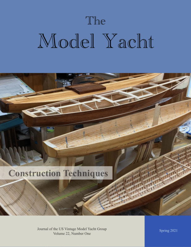
Spring 2021 The Model Yacht The Model Yacht is published three times per year by the US Vintage Model Yacht Group. Copyright 1980 to 2021 by the US VMYG. Reproduction for noncommercial purposes permitted; all other rights reserved. Other copyrights are maintained by the original holders, and such material is used here under the fair use provisions of the relevant copyright acts for nonprofit research and educational purposes. Editorial Address: John Stoudt 309 Sundance Drive Chester Springs, PA 19425 On the Cover: A range of deck and hull planking techniques, from straight edge and tapered edge planks to cold molded veneer strips, some fastened to ribs and floors, some without. In the shop of Thom McLaughlin, Blue Hill, ME. Photo by Thom. Membership Renewals: The annual membership fee will be due and should be renewed with the publication of the first journal of the calendar year. Please reference “Membership” on page 42 for dues amounts. Please use the form that accompanies this issue of The Model Yacht to complete your membership renewal. The Layline By John Stoudt Definition: A layline is a straight line (or bearing) extending from the next mark to indicate the course a boat should be able to sail on the one tack in order to pass to the windward side of the mark. (vsk.wikia.com/wiki/Layline) I truly hope that you and all of your friends and relatives have been able to stay safe and well in these trying times. We have certainly had an interesting 2020. Here is hoping that 2021 is a better year and that we can get back to doing normal things including pond sailing. Membership Dues are due at the beginning of each year. The membership form is the last page of this issue. There are three ways to pay: 1. by PayPal (using the following email address: usvmygt@gmail.com) 2. by check using the form at the end of this issue, or 3. online using the electronic membership link at: https://form.jotform.com/90405575663966/ Articles for The Model Yacht The vintage group is in a very good place with article flow for our Journal. Nearly everyone we have asked has written for us, giving us material for the next couple of years. For this the editorial team is very thankful. We ask authors to understand that their piece may not show up in print right away. It will be in the queue and be published as soon as we can fit into the featured theme or another issue. We will keep asking you to write and hope you will. If you are uncomfortable writing, get the words down on paper. We can assist with the editing. Remember, photos make the article so much more interesting. So, take good high-resolution photos and send them along. 1
Spring 2021 The Model Yacht Inside The Leadership Team……..i The Layline…………..…1-3 Barnacles………………3, 21 2020 Financial Summary….4 Deriving a Vintage 36 from a Vintage Marblehead….5-10 Photo by Judy Bonanno Photo by Judy Bonanno Building a Skeg and Rudder for a Fiberglass Hull.….11-15 Building Odyssey…..…16-18 Sanding & Finishing…..19-21 The Cutter In Deal……. 22-26 Bending Wood…………27-28 Setting Up Swing Arm Controls……………….29-31 Get One For Your Boy (for yourself)………….32-39 Resources…………………40 Boat Registration Form…..41 US VMYG Membership…42 Vintage Nationals Well we missed the event in 2020 due to the virus but are planning on being able to have vintage nationals this year. The US VMYG National Championship Regatta will be held October 6–10, 2021 and hosted by the Chester Springs Model Yacht Club. It will take place at Tel Hai Camp and Retreat Center, on their lake at 1101 Beaver Dam Road, Honey Brook, PA, 19344. The tentative schedule is: • Wednesday, October 6 (no lunch served) • 1:30 – Skipjack event • Thursday, October 7 • 9:30 – Schooner event (includes restricted class and A boats) • 1:30 – V36 class event • Friday, October 8, Mid-Regatta Day • 9:00 – Three presentations • 12:30 – Lunch and boat display/parade of boats* • 2:30 – Two presentations • 5:00 – Picnic provided by Tel Camp and Retreat Center • Saturday, October 9 • 9:30 – V36 event • 1:00 – Vintage Marblehead event • Banquet – At a location to be determined • Sunday, October 10 (no lunch served) • 9:30 – Vintage Marblehead event 2
Spring 2021 The Model Yacht *There will be two aspects to this piece of the program: the display of boats that you may not necessarily want to put in the water, and the parade of boats. Both of these features are open to any vintage model yacht. It may be a boat you sailed in the regatta or something special! What boat might it be? that yawl? a catboat, maybe a catamaran? how about a tall ship? a Boucher Albatross? You get the idea! Let us get a lot of very cool vintage boats out there for a photo shoot and some video. Lunch will be provided each day for skippers (except where noted) and available for others at a nominal fee. Spouses programs will also be made available and hosted by the CSMYC spouses. The US VMYG NCR NOR can be found at: https://tinyurl.com/2gqda9bn Budget Our 2020 budget has been posted in this issue on page 4. Please review it. If you have any questions, please feel free to contact Tom Alessi or myself. Either of us will be glad to respond to you. You will note the one line item under income is “Plans and Publications”. The US VMYG has automated purchasing and added these to our website for sale. In 2019 we sold $1,000 worth of merchandise. In 2020 that number was $1,355. A nice way to augment our bottom line. Plans/books have been sold here and in Canada, the United Kingdom, France, and New Zealand. Total Number of Products Available: Number of Transactions in 2020: Different Items Sold in 2020: Total Item Count in 2020: Total Sales Amount in 2020: 160 63 47 105 $1,355 I hope to see many of you at the pond this year! Barnacle Interesting writings on the subjects of model boat and full size boat design Taylor, Roger C., L. Francis Herreshoff: The Flowering of Genius, 1931-1972, Volume II. Mystic Seaport Museum, Mystic CT. 2019. This book covers the second half of his life and many of his most beautiful and influential designs. With 230 plans and 146 illustrations. Did you know John Black wrote a series on building model yachts that appeared in Boston Evening Transcript during 1933? If you have copies of this series, we would love to get copies. Ours are partial copies of the original articles. James D. Cooney wrote an essay for his master’s degree in 1960 entitled A Study of the Methods of Construction of Model Yachts in the Detroit Public Schools. 3
Spring 2021 The Model Yacht 4
Spring 2021 The Model Yacht Deriving a Vintage 36 Model from a Favorite Vintage Marblehead Design Article, photos and drawings by John Henderson The inspiration for the work described in this article came from discussions at the 2019 Vintage National Regatta. Members of both the Vintage Marblehead (VM) and Vintage 36 (V36) fleets noted the good sailing qualities of both fleets as well as the similarities in the class rules. In fact, the rules for the two classes are deliberately as similar as possible, with differences related only to the sizes (e.g., length, sail area, draft). Could a V36 be “scaled down” from a VM? Several members had favorite VM designs and were curious how this scaling could be accomplished. fact that it is somewhat tricky to build in planked wood made it an even more interesting candidate for “scaling” into a V36. General Scaling Effects The first step in thinking about this project is acknowledgement of some annoying facts of geometry and physics. If we reduce the length by some factor, the sail area reduces by the square of that factor, and the displacement reduces by the cube of that factor. Think about this: 1. sail area is the product of two length measurements (luff and foot), hence proportional to the square of the scale; 2. volume—which gives us the weight of water displaced—is the product of three length measurements (length, beam, and draft), and hence the cube. I was among the curious. My own favorite VM is the Mad Hatter design by Roger Stollery, with plans available in the Traditional Marblehead section of our US VMYG website. This design is somewhat unusual in its completely rounded cross sections (no defined deck edge or sheer line). The 5
Spring 2021 The Model Yacht Making Sure that the Smaller Boat Floats on its Intended Waterline An example: Suppose that we intend to scale a full-size boat down to 1/10th size for a model. The area of the mainsail of the original is: The most obvious problem revealed by these simple calculations is that straightforward scaling results in a boat that lacks volume—i.e., displacement, or weight. The V36 design would have to have a deeper and/or wider hull below the waterline to support a practical weight. My own preliminary target for my V36 was an all-up weight of 8–9 lb, with ~5 lb of lead ballast. SAorig = ½ ⨉ luff ⨉ foot Scaling the luff and foot by the 1/10th scale factor gives: SAmodel = ½ ⨉ (luff/10) ⨉ (foot/10) = ½ ⨉ (luff x foot)/102 = SAorig / 102 Although my original inspiration was the Mad Hatter, there is another similar design, also by Roger Stollery, available among our Traditional VM plans; it is called the March Hare. The March Hare is somewhat heavier than the Mad Hatter, so it seemed like a good starting point for a V36 design. In deference to its origins, I have called the new V36 design the April Bunny. Here is what happens if we apply these facts in a straightforward way to the Mad Hatter VM design, for which LOA = 50 in, SA = 800 in2, and Displacement = 16 lb: • A V36 scaled simply from this design to LOA = 36 in gives a scale factor of 36/50 = 0.72. • Therefore, a “scale” sail area would be: 800 in2 ⨉ (0.72 ⨉ 0.72) = 415 in2. • And a “scale” displacement would be: 16 lb ⨉ (0.72 ⨉ 0.72 ⨉ 0.72) = 6 lb. The design goal is to preserve the appearance of the March Hare/Mad Hatter design, but in a 36-in length with a displacement between 8 and 9 lb. With 5 lb of ballast, this leaves ~3.5 pounds for hull, rig, and radio. The waterline for this boat is defined by the bow and stern just kissing the water simultaneously, and I think this criterion must be met accurately to avoid dragging the stern or immersing the fairly blunt bow—and to preserve the full waterline length. Other hull shapes might be more forgiving of the exact waterline location, but I think this particular design requires getting the weight exactly right. The attentive reader will note that this sail area is only about two thirds of what is permitted in the V36 class, and a 6-lb boat is probably not buildable with any reasonable amount of ballast. The key take-away: Simply scaling down all the dimensions of a VM will not result in a satisfactory V36. We must modify the design somewhat to preserve the character of the original while providing volume, sail area, and stability to enable a practical smaller boat. In the end, after some exercises in drawing lines and calculating displacements, the hull depth of 6
Spring 2021 The Model Yacht the V36 was made about ¾ in deeper and about ¼ in wider than a scaled version of March Hare. In this context, “hull depth” refers to the fairbody and does not include the keel fin. Fig. 1 compares the profile of the VM design shrunken to 36 in LOA (solid lines) with the profile of the V36 obtained by including the design revisions discussed herein (dashed lines). Note the increased depth of the hull below the waterline. Note also the proportionally deeper and wider keel fin according to V36 class rules. Fig. 2. Lines of the V36 April Bunny Fig. 1. Profile comparisons. Making displacement calculations from lines drawings is tedious but not difficult. The procedure, using Simpson’s Rule, is described in my article beginning on page 22 of the Spring 2019 issue of The Model Yacht. The calculated displacement of this V36 design is 9 lb—at the high end of my target weight, but it allowed for some tolerance if I missed my light building weight goal. Although I did not make detailed stability calculations, the ballast/displacement ratio and the sail area/displacement ratio were both within reasonable ranges. Stability is enhanced because the V36 class rules allow 11 in of draft, which is proportionally greater than the 12-in draft allowed for Traditional Marbleheads. The draft of April Bunny is 10.5 in. Fig. 3 shows the finished hull, rough sanded with the rudder skeg installed. This photo may provide a more familiar view from which to judge the lines and the shape. Obviously, all of the lines in all three views – sections, profile, and plan – must be fair curves with consistent dimensions despite the increase in depth and beam. The result is shown in Fig. 2. Fig. 3. Planking finished 7
Spring 2021 The Model Yacht a small amount of weather helm), I moved the keel aft about 1 in. There were some additional factors that played into positioning the keel: Sail Plan Revisions Another design issue is the sail plan. The V36 class rules permit a proportionally larger sail plan then the VM, as noted above. To get an idea of the V36 spar lengths, we can write an equation that “scales” the sail areas—600 in2 for the V36 and 800 in2 for the VM: 1. The minimum keel chord based on V36 rules is slightly larger proportionally than the VM minimum chord. 2. April Bunny’s V36 hull is slightly narrower proportionally than my Mad Hatter. Heel angles might be slightly greater, which pushes the sails’ center of effort outboard more and increases weather helm. 3. Moving the keel aft required a slight reshaping of the lead bulb to keep the center of gravity in the same place. 600 = s2 ⨉ 800 where s is the linear scale factor for spar lengths. Solving for s gives Note that these helm balance effects are hard to calculate (and designers frequently get them wrong). I left the usual adjustment range for mast and jib positions, but I can report that the boat seems happy with the middle positions, so I got lucky. which says that we can find the edge dimensions (e.g., foot and luff) of the V36 sails by multiplying the VM sail plan dimensions by 0.866. I used the B-rig shown on the March Hare plans in order to get dimensions that are acceptable to the V36 class rules. Calculating the Center of Effort of the sail plan is straightforward and documented in many places (see my article in the Spring 2019 issue of The Model Yacht, which I referenced previously). The sail plan revisions pointed out another problem. March Hare’s B-rig jib had a bit lower aspect ratio (longer foot, shorter hoist), so the jib tack got perilously close to the bow of the V36 boat. I decided to move the mast about 1 in aft relative to its “scale” position based on the VM March Hare. To preserve helm balance (I like Building the Boat Fig. 4. Frames and planking 8 The V36 April Bunny was built essentially the same way as the VM Mad Hatter, which I documented in the Spring 2020 issue of The Model Yacht. A photograph of the partially planked boat is shown in Fig. 4. Note that there are no fulllength longitudinal frame members—not even a full-length external keel nor internal keelson.
Spring 2021 The Model Yacht Fig. 5. Framing and keel naturally in Asia, and it is considered an invasive species here. (It is actually banned in some parts of the US.) It happens that there are stands of this wood in the eastern shore of Maryland, where I live, and it has been used locally for boatbuilding. It is reasonably strong and quite light – generally a bit less dense than cedar, although density varies with growing conditions. I chose it as an experiment and because it was available locally. As Fig. 3 shows, it is generally light in color, although it can have strong grain patterns that, to my eye, are disruptive to the appearance of a small model. For that reason, I chose to stain the wood with a water-based stain, which is compatible with the epoxy overcoat. On balance, I prefer the straight grain and general appearance of a nice piece of cedar. The keel fin is locked into notches in the central frames, which are stronger plywood than the rest of the frames. The idea, which I have used before, is to tie the major stress points of the boat (keel, mast support, chainplates) together. The hull, especially with a shape like this one, forms a rigid monocoque structure to help carry stresses. The ends of the boat can be built more lightly, since they only need to keep the water out. I installed a ¼- by ¾-in king plank from Station 1 to Station 5 to provide support for the mast mount and the jib tack. Fig. 5 shows the framing in the way of the keel; it also shows the top of the keel fin locking into the central frames. Notches for the king plank are shown. I planked the boat and made most of the frames from Paulownia wood. This wood grows 9
Spring 2021 The Model Yacht Here is a list of the “as-built” weights: Bare Hull:1.75 lb Keel: 5 lb Rudder: 0.8 oz Radio Board: 11 oz (with 2000 mAhr 5-cell NiMH battery and sail and rudder servos) Rig and sails: ~ 0.75 lb Total: ~ 8.3 lb In its initial tests in moderate winds (10–12 knots), the boat seemed to perform well. Speed relative to other designs is a matter for future learning. For those who may be interested in building this Vintage 36, plans are available on the US VMYG website. Fig. 6. April Bunny under sail 10
Spring 2021 The Model Yacht Building a Skeg and Rudder for a Fiberglass Hull Article and photos by Ivor Walton T Materials list: ¾-in hardwood for keel ⅜-in hardwood for skeg ¼-in hardwood for rudder 3/4- by ⅜-in softwood, 5-in long 5/32-in brass rod 3/16-in brass tube (that nests with 5/32-in brass rod) Dubro #155 Steering Arm (5/32 in) he challenge in building a skeg and rudder is to get them perfectly aligned with the keel. Accurate drilling is required, so a drill press with a drill vise is recommended. For this project I used a fiberglass hull for a V36 Chico II from Blue Crab Model Yachts. I modified the shape of the skeg compared with the one on the plans in order to simplify the building process. 11
Spring 2021 The Model Yacht The hull requires an additional layer of ¾-in wood between the fiberglass keel and the lead ballast, which is pinned in place with two 5/32-in brass pins. It will be secured with screws and epoxy after the lead ballast has been attached to it. Drill the two holes for the pins through the wood with a drill press so that they are exactly perpendicular to the waterline. Then, holding the wood in place on the keel, continue the holes through the fiberglass keel with a hand drill. Put a 5/32-in brass pin through the first hole before drilling the second one. Leave the pins loose at this time, and leave a couple of inches protruding above the keel. The next step is to epoxy a piece of ¾- by ⅜-in wood inside the hull that is long enough to span the area where the skeg and the rudder tube will be. This will be the support for both the rudder tube and the screws that fasten the skeg. To drill a true vertical hole for the rudder tube, the hull must lie perfectly flat (side-to-side) on the drill press. If the port and starboard sheers are not exactly the same height, one side must be filed down. You can either sight down the protruding brass pins on the keel to check that they are vertical or, better yet, use a spirit level on the pins. Now use the drill press to drill a 3/16-in hole through the fiberglass and the wood. Before epoxying the rudder tube in place, check the alignment between the rudder tube and the two pins on the keel. All three should line up. 12
Spring 2021 The Model Yacht Epoxy a 3/16-in brass tube in place, leaving a couple of inches protruding both inside the hull and outside. Add thickened epoxy inside the hull to secure the rudder tube to the wood. Cut the skeg to shape from a piece of ⅜-in hardwood so that it fits snugly between the hull and the rudder tube. The Chico hull has a slight bulge where the skeg is located so the underside of the skeg must be hollowed out to match the shape of the bulge. Now carve and file a ¼-in diameter semicircular groove in the back of the skeg where it meets the rudder tube. Put the skeg in the drill press vise with the base horizontal and facing up, and drill two 3/32-in holes all the way through the skeg, on the centerline. The picture to the left shows where to drill the holes. Wrap four or five layers of blue masking tape around the front of the rudder tube. This provides the clearance needed for the rudder to rotate. Draw a centerline along the hull at the front of the skeg. 13
Spring 2021 The Model Yacht Now position the skeg up against the taped rudder post and tape it to the post, making sure that the front of the skeg is on the centerline of the hull. Hold the skeg firmly in place and drill down the two previously drilled 3/32-in holes with a hand drill through the fiberglass and through the wood block inside the hull. You will need an extension drill to do this. (If you don’t have an extension drill (jobberlength bit), workaround would be to cut the skeg in half horizontally, follow the steps above, and then glue the skeg back together.) Open up the holes through the wood block and the fiberglass to accept small-diameter screws that are long enough to secure the skeg to the hull. Remove the tape from the rudder post and screw the skeg to the hull. If the skeg doesn’t line up perfectly with the rudder tube, file either the base of the skeg or the fiberglass hull until it does. This may take several attempts. When the fit is satisfactory, cut the rudder tube where it exits the fiberglass, making sure that the cut is perpendicular to the tube. Taper the skeg toward the leading edge, fill the two holes with wood filler, sand it smooth, and epoxy and screw it to the hull. 14
Spring 2021 The Model Yacht The rudder is next and is a lot easier. Cut the shape from a piece of ¼-in thick hardwood. Carve and file a 3/16-in diameter semicircular groove into the leading edge, and epoxy a 3/16-in brass tube into the groove. Use thickened epoxy to make a fillet between the tube and the end of the wood. Cut a length of 5/32-in brass rod for the rudder post and epoxy it into the 3/16-in tube. The next step is not mandatory, but I epoxied two 1/16-in brass pins through the brass and into the wood for added strength. Taper the rudder toward the back to about a ⅛-in thickness and sand the leading edge to a nice smooth radius. Cut the rudder tube inside the hull to the correct length and cut the rudder post so that it extends about ⅜ in above the rudder tube. I file a flat on the forward side of the rudder post so that the rudder arm lines up correctly when the set screw is tightened. I use a Dubro #155 Steering Arm (5/32 in) from Tower Hobbies. 15
Spring 2021 The Model Yacht Odyssey Building I was waiting, expectantly, like a 10year-old. The Post Office had sent me a notice that I had a package to be delivered that afternoon. I knew it was the 40-year-old sailboat kit I had bought on eBay, and I could not wait to see what it looked like. And then the box arrived—crushed in several places and held together with tape that said it had been re-sealed at the Post Office. On further inspection I found that the plastic hull had been cracked open along the transom and a piece of the transom was missing. Who knows what else is broken or missing, I thought? Being 70 years removed from that 10-year-old boy (although I still consider myself a 50year-old trapped in an 80-year-old body) the first thing I did was try to contact the seller to let him know about the situation. Once that failed, I went to eBay and PayPal to file a claim, which was in good time resolved in my favor. Article and photos by Michael Neben Then began the odyssey of building this kit. Three things saved me from total failure: 1) in my old age I’ve learned to be patient and resourceful; 2) I’ve been sailing and owning sailboats since I was 19; and 3) I already own two R/C boats, a DF 65 and a DF 95, so I’m familiar with R/C control systems. 16
Spring 2021 The Model Yacht to your own measurements. Once the hull was completed and the servo tray and associated controls were in place, the pre-formed and finished deck needed to be glued to the hull (by the way, the deck detailing and finish were a thing of beauty, probably the highlight of this kit). There was a tiny flange on the hull to use in the gluing process, but the deck had substantial overhang so it was at best a process of guesswork. Then the instructions called for the flange to be ground (filed) down flush. When that was finished, it looked terribly amateurish and not at all like the fine yacht it was supposed to represent. The first task was laying everything out to discover what was there, what was missing, and what the condition of everything was. Using the full-scale drawings provided and my trusty cell phone language app to translate the Japanese writing, I found that I had all of the critical parts. The instruction manual that came with it was a barely adequate translation of Japanese to English and didn’t coincide with the scale drawings correctly, leaving it something of a guessing game to figure out what went where. This kit, called a “Peerless Newport” by Kyosho, was meant to be a freesailed boat with the added After inspecting one of the hand-crafted boats made feature of having an electric motor, propeller shaft, ______________________ by one of the members and prop to get it back of my R/C sailing somewhere along the The deck detailing and finish club, I fashioned a toe shore. So, it meant that rail of a piece of ⅛were a thing of beauty, there was no servo tray by ⅛-in stock that or clear locations for probably the highlight of this kit. found at Michaels running control lines ______________________ Craft Store laid along through the hull and deck. the top edge of the deck and a vertical ¼- by ⅛-in As I was finishing the hull and the interior frames, around the outside of the hull. Once stained the same I kept thinking about where to place a home-made finish as the deck, this looked very authentic, and servo tray and how to run the control lines. Once I I’m sure it added to both the structural strength and got the wooden deck glued to the hull, I would not water resistance of the boat. be able to go back and design and install these necessary controls. (I did not install the electric Now to the cabin house and cockpit. Whoever motor, being the purist that I am). designed these was obviously not an R/C sailor. The person who previously owned the kit had The cabin house was a piece of thin vacuumcompleted the construction and attachment of the formed plastic that was supposed to be glued to the keel. That left the skeg and rudder assembly to be top of the deck using a flange on the bottom. It not completed. Both (as well as the keel) are hollow only looked ugly, but the mast went through a hole plastic sections (halves) that needed to be glued in the cabin top, making it necessary to remove the together and then faired and glued to the hull. mast to take off the cabin house (if it was converted Nowhere in the instructions did it mention “filler” as I did for R/C) to get to the battery, servos, and for the skeg or rudder, or how and where to place receiver. My first attempt at solving this was to cut the rudder post inside the rudder itself. The the plastic cabin house in two pieces, leaving one completed rudder post assembly had to be mounted piece in place for the mast housing and the other inside the hull at an unmarked location. The only piece removable to get to the mechanisms. It looked way to judge where was to locate the skeg and AWFUL. It was awkward to operate. And it was not rudder on the drawings and place them according watertight. 17
Spring 2021 The Model Yacht provenance of the boat (I cannot find it anywhere) or solutions to her sailing capabilities. If anyone knows of other Peerless Newport boats, I would appreciate hearing from them. Using 1/16-in beech veneer sheets (I think about 5 ply, because while it bends it is relatively stiff) I built a mast housing that rises from the deck about ¾ in and completely encloses that area, which is permanently cemented to the deck. Aft of that I built, of the same beech, a fairly authentic looking cabin that is removable to get to the interior (servos and receiver), and again using the 1/16-in beech I built a sunken cockpit that is also removable to get to the battery and the rudder post. Once stained and varnished I added “portlights” using the backside of brass grommets with a piece of blue self-stick vinyl in the inner circle, both glued to the cabin sides. Mike Neben has been sailing big boats for over 60 years and has owned, built, and restored numerous sailboats. He currently sails a Catalina 30 out of Dana Point, CA. This was his first attempt at building a kit boat, but it probably will not be the last. He can be reached at mikeneben@gmail.com. Now came the time to sea trial Odyssey. I took her over to our large community swimming pool and launched her. Fortunately, she did not sink, and she actually sailed across the pool, tacked when I pushed the lever on my transmitter, and came back to my spot. She took on a little water, but I knew it was mainly from the deck-top structures not being fitted watertight. It did give me an opportunity to mark approximate waterlines, however. Back at the workshop, it was time to paint and try to waterproof. I decided to paint the bottom red and the topsides white with a ⅛-in blue waterline stripe. Now that she’s finished I have several issues: 1) she is quite tender and heels excessively ( I have tried adding weight to the keel and that helps somewhat but she is already heavy and slow); 2) she is still taking in water (although this may be solved if I can keep her more upright); and 3) I’m not happy with the set of the sails. The last one may be fixed once I get out my trusty sewing machine and take about 1 in off the foot of the main at the clew and then leave it loose-footed. While not typical of sails from that period, it works well today and probably will not diminish the accuracy of the boat anymore than I already have in the topside redesign. So, that is the story of Odyssey. I welcome any suggestions and feedback, both about the 18
Fall 2020 The Model Yacht Sanding & Finishing Article, photos and illustrations by John Stoudt Having been an industrial arts teacher I apply a lot of what I was taught and what I have learned to model yacht building and restoration. So here are some methods I use that have worked well for me. There are other processes individuals use that are just as successful for them as these are for me. I prefer hand processes over “power” processes, although sometimes the random orbit sander has to come out of the cabinet. Preparing a wood surface for finishing There are a number of steps that you should go through as you prepare a wooden surface for finish. This is assuming the wood is either new or that the old finish has been removed. 1. Carefully examine the surface to be finished for defects. 2. If there are dents in the surface they can be repaired by raising the grain. Start by applying a drop of hot water to the dent. Place a small piece of hot water soaked fabric over the area. Allow it to sit there for a few minutes. This should raise the grain and bring the depressed area back up in line with the rest of the area. If this does not work, go through the steps again and use a steam iron (or soldering iron) on the soaked fabric. This will change the water to steam and cause the wood to swell, quickly removing the dent. 3. You will need to sand the area flat as it will be rough and the dent may have been raised above the surface. Use a sanding block on a flat surface or a sanding board on a curved surface. 4. If there are small scratches or small surface defects, sand them lightly. Do not get too aggressive here. These will likely fill in as you apply and build up your finish. 5. Make sure you wipe the surface with a solvent to remove grease and oil. 19 6. Make sure that all traces of glue are sanded out or removed with a thinner appropriate for the glue used. 7. A good sanding can remove any stain that may have been applied to the wood. 8. Nail holes, poor fits, and large defects can be filled in a number of ways. I have success using epoxy (West System) to float a clear fill over an area prior to applying the finish. If you are going to stain the surface do that first. Stain will not penetrate the epoxy. (see the Rub Rail article in The Model Yacht, Vol. 20 No. 2, Summer 2019 on p. 17.) 9. Next, sand the entire surface with a sanding block (see Fig. 1) if it is a flat surface and with a sanding board if it is a curved surface. Start with 100-grit open face sandpaper and progress through 180- to 220-grit paper. Make sure you vacuum and a fine dust brush to remove the dust after each sanding. Then wipe with a tack cloth. Fig. 1. Sanding block Note: You are trying to get the flattest surface possible prior to beginning the application of your finish. Fig 2. Magnified surface of the wood before sanding 10. Wipe the surface with a wet rag. Re-sand with 220-grit sandpaper, vacuum, wipe down with denatured alcohol.
Fall 2020 The Model Yacht Comments on Finish Finishing your boat There are many finishes you may use to finish your boat. Some of you have your own favorite. Use whatever you are comfortable with. I happen to be partial to a product called Waterlox (original). I first used this product in 1966. I was studying woodworking in my undergraduate degree program and discovered this product in the feed and grain store down the street from my dormitory. I purchased it because it was a tung oil based product. It is a resin-modified tung oil wood finish. The finish being pushed by the professor was a shellac and varnish finish. I was making something out of teak and he was concerned about the way his recommended finish would work over a very oily wood like teak. So I stepped out on my own and used this product on my project, which was by the way a silver chest. The finish worked fabulously. It was the talk of the class and to the chagrin of my professor. I got an “A”. He deemed it, “smooth as a baby’s _ _ _!” Back to the Waterlox! It is a product that provides a warm amber appearance after the correct application of the finish. I often get comments about the appearance of the decks on my boats. The one drawback is that it takes numerous coats to get the buildup needed for the finish I want. Sometimes as many as many as 12 to 14 coats, as it goes down very thin, like “water”. Waterlox is a durable finish and one that is very forgiving. If you get a scratch in the finish you can sand the area lightly with very fine sandpaper or 0000 steel wool and wipe on several coats of finish with a lint free rag to restore the appearance. This discussion relates to the use of a very watery finish. If you use a thicker product (marine varnish) you would apply fewer coats. Make sure you use a high quality brush designed for clear finishes. I prefer to apply the finish by hand rather than spraying it. 1. Once you have prepared the surface apply your first coat of finish. 2. After the first coat of finish was applied and dry, sand it out using 220-grit sandpaper and a sanding block. You want to knock down the high points and “fill” the low areas. Fig 3. Magnified surface of the wood after first sanding Note: Make sure you brush across the grain and that you cover the entire area. Look at the reflection of the finished area to see areas you might have missed. Caution: Be careful not to sand across the grain. If you have to sand out scratches do this carefully by sanding with the grain. 3. Vacuum the dust off of the surface (use a fine 4-in paint brush to dust the residue into the vacuum nozzle) and wipe the area with a tack cloth. Then wipe the surface again with denatured alcohol. 4. Apply a second coat and repeat the procedure of sanding lightly, cleaning, and applying your finish. As you continue to apply finish and sand the surface, it will become one plane. Fig 4. Magnified surface of the wood after first sanding with a coat of finish applied 20
Fall 2020 The Model Yacht 5. Repeat applications until you have six coats of finish built up on the deck. Fewer if you use a thicker finish. 6. Now switch your application technique. Begin to apply the finish with a lint-free rag. I usually apply an additional six to eight coats of Waterlox this way. You can control how wet the surface is using this wipe on technique and you can allow finish to puddle in areas if necessary. 7. At this time you will want to change sanding technique to use 0000 steel wool (very fine) after each coat of finish. 8. Continue to vacuum and clean the surface in the same way. 9. The last coat determines the glossiness of the finish. I prefer matt finishes so I rub out the finish aggressively which shortens the dry time and produces the semi-gloss finish I like. You can rub out the last coat of finish after a light sanding with the 0000 steel wool using pumice and oil (satin) or pumice and water (glossy) to control the sheen of your finish. Note: Use a high quality brush designed for clear finishes (varnishes, etc). Clean it well between applications of finish. Clean first with the appropriate solvent for the finish being used, wipe out the solvent on newspapers, and then clean the brush with soap and warm water. Shake out the excess water and carefully wrap the brush in paper towels to protect and wick the water out of the bristles while it dries. It will be ready when the coat of finish dries. WaterLox can be found online and at Woodcraft, large hardware stores and other suppliers. It sells for about $35.00 per quart. I have never warmed up to their VOC-compliant product. Barnacle Another resource for model boats plans and more – You’re probably familiar with the Boat Plans store page on our US VMYG website: https:// usvmyg.org/store/plans/ But Model Boats (British) magazine also has a slew of plans available, from model sloops, catamarans, cutters, clipper ships, motor boats and yachts, to a pirate brig, and a scale model of a bamboo raft built to prove that the ancient Asian mariners had reached America, across the Pacific, long before Columbus. They even have a set of plans for a variety of Braine and vane steering and sail control devices. The link is: https://www.sarikhobbies.com/product-category/model-boat-builder/plans/sailing-boats-yachts/ 21
Spring 2021 The Model Yacht The Cutter in Deal Article and photos by Jonathan Kinghorn I’m an enthusiast for both the cutter rig and early free sailing models. Back in 1998, when I last wrote an article for The Model Yacht, I was beginning to build a large sailing model of a 25-ton cutter yacht following instructions I’d found in a magazine from 1870. Drawings were drawn, sawdust was made, and I even sourced sheets of mica for glazing the skylights, but before long I was frustrated by the design’s many impracticalities. Fortunately, I stumbled upon something even more exciting. A tiny museum in Deal, on the English coast just north of Dover, contains a true gem from the early 1830s. It is an impressive sailing model of a 10-gun naval cutter almost 5 ft long overall and 5 ft tall. Almost everything on it originally worked—including the pump and the guns! And as if it couldn’t get any better than that, a sheet of paper found inside the hull contained detailed notes written in 1908 to record the model’s origins. The note was written by 77-year old Frederick Harvey, whose father and uncle had built the model in Deal with the help of a servant and a neighbor. All four were veterans of the Napoleonic Wars and the War of 1812. The Harvey family owned significant property in the area and had an extraordinary naval heritage. At least two dozen of them followed naval careers or married naval officers between the 1750s and 1920. Frederick’s father and uncle, Henry and John, had six uncles and first cousins who became admirals, and their heroic grandfather has a monument in Westminster Abbey! John chose Able Seaman James Butler as his servant when he joined his first ship as a midshipman in 1804 and retained him for 53 years. The neighbor, Captain John Watts, was an infantry officer who served in the final phase of the Peninsula War and in the attacks on Washington, Baltimore, and New Orleans. Construction of the model started in a workshop at Captain Watt’s home in 1830 and seems to have coincided with the birth of Henry’s first son, Frederick. Watts moved to nearby Walmer Castle (the official residence of the Lord Warden of the Cinque Ports) when he was appointed Captain of the Castle in 1833. In that role Watts served as personal assistant to the Lord Warden, the Duke of Wellington (who later retired to Walmer and died there in 1852). After serving the next Lord Warden, Watts became Lieutenant Governor of 22
Spring 2021 The Model Yacht Dover Castle in 1860 and ended his days as one of the 12 Military Knights of Windsor Castle. The cutter was evidently completed in about 1836 by Henry Harvey at his home in Middle Deal House where young Frederick helped make rope and the ladies of the family sewed the sails. beam of 14 in, was carved from a single block of timber and hollowed out with a gouge. Beams of beechwood support the deck, which is a thin sheet of wood with a slight sheer but no camber. A wide whale was nailed on to mask the join between the hull and bulwarks. Neatly cut rebates around each of the gunports suggest that gunport lids were planned, but there is no sign of them having been fitted. The rudder hangs from just two pintles, like that on a small boat, and while the more substantial lower spars appear to be original, the gaff and topmast are clearly replacements. It is not known what led these four men to build their sailing model. Organized model yachting was in its infancy in the 1830s, with working class men racing informally on a reservoir in London’s Green Park, for example. But there were no clubs, magazines, or how-to books available. We know that Butler built a 4-ft high working model of a corn mill that could winch up miniature sacks of grain and grind them into flour. If this was built before the cutter, maybe it inspired the sailing model. Or could Frederick’s birth perhaps have been the catalyst? A sailing model would have been a great way to prepare the boy for his almost inevitable naval career. (Frederick ended his service in 1873 as an instructor for the primitive torpedo that he and his uncle had developed—one of the first adopted for trials by the Royal Navy.) Frederick recorded that the cutter was sailed in a low-lying flood-prone spot a mile from Middle Deal House behind the beach at Sandown Castle, “where the sea overflowed”. Its guns could be charged with gunpowder and linked with a lit fuse to go off one after another as she sailed! In his note, Frederick described and sketched the method used to provide a degree of helm control. This consisted of a lead bullet on the deck linked by a line through eyebolts in either bulwark to the tiller. As the model heeled over the bullet slid across the deck, pulling the helm over in the opposite direction. The cutter’s hull, which is 36-in long and has a Fig. 2. The cutter’s helm control as reconstructed on the copy 23
Spring 2021 The Model Yacht Beautifully modeled reefing gear on the boom implies that the cutter’s original mainsail had four lines of reef points and could possibly be reefed! The reeving bowsprit can be set at three different lengths, and there may have been a corresponding jib sail for each of them (real cutters would have carried half a dozen). There may also have been both fore-and-aft and square-rigged topsails to set as conditions warranted. The 5-lb strip of lead dovetailed and screwed into the keel may not be original, and she could simply have been ballasted with some of the fine shingle forming the adjacent beach. The historic model cutter has, unfortunately, been altered by two well-intentioned but ill-informed restorations. The first of these was probably carried out by Adams himself and seems to have recommissioned the cutter as a usable sailing model in about 1900. The workmanship was crude and shop-bought model boat fittings were used. This was a typically Victorian “restoration” in that it evidently embellished the model with non-functional features such as a binnacle and stern davits. Thus improved, the cutter became a feature of the summer home in Deal. Adams’ son inherited the house and its contents in 1944 and gave the cutter to the town 2 years later to join a collection of model boats accumulating in the Town Hall. These models were eventually stored, and when it was rediscovered in the early 1960s the cutter needed significant repairs once more. This time it was competently restored by a local ship modeler (a retired merchant navy captain) and emerged in 1965 as a more-completely rigged static exhibit. She had acquired anchor buoys, boats, white nylon rigging, and new sails sewn by the restorer’s wife. The town gave its collection to the Local History Society in 1973, and the cutter is to be found today in their Maritime Museum, about 400 yards as the crow flies from where it was originally completed. The model remained with the Harvey family into the 1890s, but by then the guns had been stolen “by some tramp” and it seems to have been in a sorry state generally. The cutter passed to a friend of Frederick’s youngest brother, Edgar Adams, who built a summer home in Deal in 1893. Adams was a wealthy brewer with a wide range of interests. He was a gifted artist and photographer, for example, and a keen sailor and an avid collector of maritime artifacts. His superb navigational instruments form the core of the collection at the National Maritime Museum in Greenwich, but he also accumulated books, prints, and model ships. Fig. 4. The foredeck of the copy is still a work in progress Fig. 3. The foredeck of the historic model as restored in the 1960s 24
Spring 2021 The Model Yacht The copy is not carved from a block of timber but built up from vertical lifts cut from 1-in pine boards. Marine plywood has been used for the deck to prevent it from splitting like that on the historic model. Modern paints and adhesives have been used, but there is no plastic—only wood, lead, and brass. Although it seems unlikely that the cutter had ground tackle when built, Admiralty pattern anchors have been fitted. Here I treated myself to a little 21st century technology. Since no anchors big enough are available from suppliers—and to save time and improve the end result—the anchors were cast in brass from 3D-printed wax patterns. The only shop-bought fittings used on the reproduction cutter are the brass pulley wheels for the blocks and the rigging rope. Following traditional shipwright practice, a silver coin has been placed under the mast for good luck. For many years I have been researching the historic cutter and the men who created it so I could build a copy. The initial goal was to reconstruct the model’s original form and functionality following the many clues that it retains. No sailor would belay more than one line to each belaying point, for example, and sheave holes in the yardarms of the square-rigged crossjack yard can only be there for the sheets of a long-lost square-rigged topsail. There is, however, no evidence for how—or indeed if—the cutter was originally painted, so the appearance of a pair of cutters in an 1842 watercolor by Henry Harvey was reproduced. Clearly, the cutter was rigged following full-size practice, but in a simplified form. With no rigging for a traveler on the bowsprit apparently possible, for instance, the jib sail probably hooked to an eyebolt at the tip of the spar, but this isn’t certain. Because there is no clear evidence for many aspects of the model like this, an authoritative reconstruction of its original configuration proved impossible. As it progressed, my copy therefore developed more into a demonstration of what the model probably should have become had its restorers known better. The diminutive shop-bought cannons fitted in the first restoration have, for example, been replaced by period-correct Fig. 5. The cutter’s carronades laid out on the working 18-pounder carronades modeled drawing used for the copy to the cutter’s assumed scale of ½ in to the The project was possible because the museum’s foot—and they fit the gunports perfectly! They curator kindly removed the cutter from its were made by a guy in Wisconsin who reported display case so it could be measured and that a test firing produced a very loud bang and an photographed; lines were also taken off the hull impressive amount of smoke! 25
Fall 2020 The Model Yacht using a custom-made profile gauge. Armed with this information, the cutter was first reconstructed on paper. After I moved to the US, construction began in the early 2000s with the help of a US VMYG member in Swampscott, MA, who cast the lead for the keel. Because life kept getting in the way, the project has proceeded slowly. Today, the hull is complete, all spars have been made, and a suit of nine sails has been commissioned from Nylet in the UK. Fabrication of the 95 working blocks required has begun, and preparation for the rigging has commenced. The copy floats nicely but only time will tell how well she actually sails. Fig. 6. The copy set up with temporary rigging and paper templates for the principal sails 26
Spring 2021 The Model Yacht The Last Episode Article, photos and illustrations by John Stoudt This article is not technically about bending wood. It is about using the bent wood hatch rim, made using the ammonia process, to complete the new hatch on BlackWatch, a classic Marblehead. The new hatch is designed to use the original hatch cover to keep the grain match between the cover and the deck on the boat. The reason for this exercise is that the original hatch cover (OHC) did not fit correctly on the deck opening on the boat. Fig. 1. Original Hatch Cover (OHC) The hatch cover did not have the same curvature that the deck had; therefore, it would not seat on one side of the opening. This allowed water running along the deck to spill into the bilge. I described the procedure to make the bent hatch cover frame in The Model Yacht, Volume 20, Number 1, page 19. Hatch Cowling Fit onto Deck Making the new waterproof hatch was a multistep process. The bent wood hatch frame was built directly on the cowling, using the cowling as the mold. The fit of the new hatch cover was controlled by the masking tape placed around the cowling where the bent hatch frame was constructed. Refer to Part 3 of this series. Close Up of Hatch Frame (Bent). 27
Spring 2021 The Model Yacht 1. A hatch cowling was cut out of a ¾ x 6 x 8-in mahogany. This was carefully fitted into the groove on the deck and adhered with thickened 1-hour epoxy. A small fillet was formed around the outside seam between the cowling and the deck. The inner edge between the deck and the cowling was sanded fair. 2. The original hatch cover was carefully epoxied into the top of the bent wood hatch frame. A fillet was formed around the inside corner of the hatch cover and the hatch cover frame. 4. The entire assembly was sanded to fair in the cover and the finger grips, and to round the edges and shape the bottom of the new hatch cover. 5. Finishing the cowling and hatch cover began with a coat of epoxy. Both areas were sanded to remove excess epoxy, smooth out the area and prep it for the application of the waterproof finish. Multiple coats of WaterLox were applied and allowed to dry. After each coat dried, the surface was sanded lightly to control high spots and increase the smoothness of the surface finish. The final coat was applied with a lint-free rag and rubbed out to allow for a semi-gloss finish. Care was taken with the deck area around the cowling installation to not damage it much by the sanding process. Fig. 2. Finished Hatch Cover (OHC, original hatch cover; HC, hatch cowling; NHC, new hatch cover). 3. Finger grips were fastened to each side of the new hatch cover to assist lifting the hatch cover off the boat. The new hatch cover performs well, allowing no water into the boat and incorporating the original hatch cover into the new design. Finished Hatch Cover 28
Spring 2021 The Model Yacht Setting Up Swing-Arm Sail Controls Article, photos and illustration by John Henderson Servo arm length Everyone who has built an R/C boat has There are some practical faced the problem of how limits. The length is Fig. 1. Servo Arm Travel to get the sails to trim over their constrained by the beam of the entire wind angle range without stalling boat. If you want to use oppositethe servo at either extreme of its travel. side arms of equal length on a single For those who have not already worked out servo to control the main and jib, then the a formal procedure of their liking, I offer in this maximum length of each arm is a bit less than half note a straightforward method that is easy and of the beam after allowing for planking thickness minimizes trial and error. and internal frames. If the arms for the main and jib are of unequal length, the sum of the lengths The variables under our control are: must be less than the beam. (Always check the 1. length of the servo arm. swing for interference over its entire range.) 2. sheet attachment position on the boom. 3. height of the boom above the deck The length is also constrained by the available torque. (although this has a much smaller effect The longer the arm, the more torque is required. The than the first two items). necessary torque depends on the sail area, wind 4. choice of servo – both the rotation range strength, and friction on the sheet(s). I know of no (the number of degrees through which it easy formula for these factors. Look at the servos rotates) and the torque (which might affect that have worked for similar boats. For the purposes how we use mechanical advantage). of this article – which is about determining the lengths 29
Spring 2021 The Model Yacht effectively. The attachment point is measured from the gooseneck “hinge”. Pick a distance (say, 12 in) and mark it with tape. Now, with the mast and boom installed and the boom in position at the height above deck that you expect for sailing, make 2 measurements: of sheet lines and arms – I will assume that a servo of adequate torque is available. The first step is to measure the linear distance between the locations of the end of the arm at each extreme of its travel range. See Fig. 1 where the “maximum linear travel distance” is shown. The figure shows the swing arm positions for a servo with its (one-sided) arm at each extreme of rotation. The “maximum linear travel distance”, as shown in the figure, is the measurement needed, and it depends on the length of the arm and the rotation range of the particular servo. Note: this must be done using the transmitter to move the arm; it is not unusual for the servo to have greater available range of travel than is achieved using the signal from any particular transmitter. You also must account for how transmitter trim adjustments affect this range. 1. with the boom trimmed to close-hauled (near or at the boat’s centerline), measure the distance from the deck fairlead to the boom attachment point. 2. with the boom all the way out (presumably hitting the shrouds or close to it), again measure the distance from the deck fairlead to the boom attachment point. The difference between these two distances is the amount of sheet you need to pull in for that particular attachment point. Adjust the assumed attachment point, and repeat these measurements until you match the amount of string that the servo arm can move. The amount of sheet line that you can pull in is directly related to the distance you just measured. If you attach the sheet directly to the arm, then the available amount of sheet length change is exactly the distance you measured. If you pass the sheet through the arm and then back to an attachment somewhere in the hull, then you can pull in twice as much sheet line – but this comes with a mechanical disadvantage of 2:1, so more torque is required. This is the “no free lunch” rule of physics. Fig. 2 A and B show the boom in each of these positions with the ruler in place to show the difference in sheet length. In this particular Position of attachment to the boom Having determined the maximum length of string that we can move with the selected servo and arm, we now find the boom attachment point that uses this length Fig 2A. Full Inboard Trim 30
Spring 2021 The Model Yacht hatch. In this case, you might start with the boom attachment location and work “backwards” to get the arm length. If the boat is arranged so that the jib and main are controlled by the same sheet, then the attachment on the jib boom should be the same distance from its pivot point as the main is from the gooseneck. If the main and jib sheets are led to opposite sides of a servo arm that sticks out on both sides of Fig 2B. Full Outboard Trim example, the close-hauled (inboard) measurement is about 3 ¾ in, and the outboard measurement is about 10 ½ in, which requires the servo to move about 6 ¾ in of sheet line. I used a 2:1 arrangement with a wide-rotation sail servo and an arm length of about 2 in, which could move the necessary amount of line. (The boat is a fairly narrow Vintage 36, and I used equal-length opposite-side arms for main and jib, so arm length was a very real constraint.) the servo, then there is more flexibility because the arm lengths are not required to be equal. As a practical matter, it is often easier to make a symmetrical arm and equal boom attachment point lengths. If you use the 2:1 arrangement, then you must find a suitable attachment point above or below deck for the “dead end” of the sheet. This point must be at or beyond the maximum travel of the swing arm, or else the full benefit of the 2:1 arrangement will be lost. Some additional comments Note that if you use opposite sides of the servo for main and jib, then the respective sheets must be led from opposite ends of the servo – typically, the jib sheet through the deck forward of the servo and the main sheet aft. The description above starts with a given servo arm and adjusts the boom attachment. You could just as well start with the desired boom attachment point and then determine the necessary servo arm length. It is often desirable, for example, that the boom attachment point be more or less directly over the deck fairlead and that fairlead’s location may be constrained by (for example) the deck Double-check your installation to be sure that the main and jib angles track each other over the full range of wind angles. 31
Spring 2021 The Model Yacht Get Your Boy One (For Yourself) Article and catalog copy by Peter Kelley It may not have been nearly as inspirational as “Just Do It” (Nike, 1987), nor as unforgettable as “Finger Lickin’ Good” (KFC, 1952), but over 100 years ago “Get Your Boy One (For Yourself)” was the slogan used to promote Boucher Inc., a relatively little-known American manufacturer of model sail- and powerboats. As slogans go I think Boucher’s has stood the test of time quite well. A quick introduction: I am Peter Kelley, US VMYG’s recently appointed Class Coordinator for Vintage Power Yachts and, for the past 35 years, a collector of vintage model yachts, both sail and power. Because the world of model powerboats is new to the US VMYG, I will periodically write about them. I thought I would start first with this brief look at the scale model powerboats manufactured and sold by Boucher Inc., a New York City-based company that operated from 1905 until about 1950. (I have never found any actual record of the company’s demise, and certain parts of the company’s business appear to be carried on to this day by others. See Bluejacket Ship Crafters, which claims Boucher as part of its corporate heritage.) Boucher catalog 32
Spring 2021 The Model Yacht So, why start with Boucher? Well, Boucher Inc. was more than just a “toy” manufacturer; it was founded by Horace E. Boucher (1874– 1935), a college-educated naval architect who served as head of the model shop of the US Navy in Washington, DC, from about 1895 until 1905. As a result of the training and experience of its founder, the model boats later produced by Boucher Inc. were beautifully engineered, wonderfully crafted, and awfully expensive for the time. These are characteristics which have heavily shaped my collecting preferences. While there were several manufacturers of model power- and sailboats in operation at the time in England and Continental Europe (Bassett-Lowke, Marklin, Radiguet, Kellner) Boucher Inc.’s “model studio” in New York City was unique to the US. The new business allowed Horace Boucher to continue his commercial ship modeling work (for the Navy, as well as for private shipbuilding and marine engineering firms) while massproducing ready-to-launch model power- and sailboats sold through the company’s own catalog and also through high-end toy retailers like FAO Schwartz. And, in case the finished product was too expensive for your blood (as it must have been for many, as you’ll see below), each component of each model boat was offered for sale separately or in pre-cut “construction set” form through Boucher’s catalog as well. Boucher promoted his catalog of models through small advertisements placed in relevant periodicals, ranging from the modelmaking and model engineering monthlies that were then popular to science and mechanics magazines and, occasionally, in preChristmas editions of the New York Times. Leitch cover page Boucher’s hand is also clearly evident in the book Miniature Boat Building (Leitch, Albert C. (1928) Norman W. Henley Publishing Co., New York) which contains over 500 illustrations of “construction methodology” for a range of model sailboats and power speedboats, each of which happens to be identical in dimension and design to those offered in Boucher Inc.’s 1922 catalog. (Aside from a fullpage “Boucher Inc.” advertisement on page 243 there is no reference to Boucher anywhere in Leitch’s book, but I 33
Spring 2021 The Model Yacht would note that all of the diagrams of the different power plants, boilers, and torches contained therein refer to each variant using the same nomenclature as does Boucher’s catalog. (The high-speed 4cylinder steam engine is, in both cases, called the “S-74”, for example.) Personally, I believe that “Albert C. Leitch, Naval Architect” is, in fact, the nom de plume used by “Horace E. Boucher, Naval Architect”, but Boucher ad 34 since I have yet to find anyone else who cares I haven’t bothered trying to prove it. So, some focus on the line up of powerboat models produced by Boucher Inc. is in order. Most of this material comes directly from the several Boucher catalogs that I have collected over the years. Boucher Inc. did not issue catalogs annually; it did, however, send “aged” catalogs out with fresh price lists where necessary. For the most part the product offering remained substantially the same over those years for which I have catalogs, from 1922 into the 1940s. All of the products are well illustrated in a combination of line-drawing and black and white photography. In addition to the stock offerings, the earlier catalogs each offer hand-built, commissioned custom jobs, built to the plans or specifications of the customer. Although shortly after the death of Horace Boucher in 1935 this service was no longer offered in any of Boucher’s catalogs. These “custom jobs” are quite rare. In over 35 years of collecting I have managed to find only three: a 5ft, 4-cylinder, steam powered “racing launch”; a 3-ft, 2 cylinder, steam powered “open launch”; and a 30-in single cylinder, steam-powered singlestep racing hydroplane.
Spring 2021 The Model Yacht In addition to the Minnow, the stock line consisted of four progressively larger model launches, all steam powered. The four are similar in design and construction but with slightly larger plants and boilers as the hull size is increased. At 30 in, the Snapper was fitted with a single cylinder plant and was designed to give the boy captain “experience in handling engines, boilers and fuel”. On a more upbeat note, the catalog states that Snapper was designed to provide a “maximum of Safety with steam Power”. Catalog picture of Minnow Initially, Boucher offered a line of five stock model speed boats. The “entry level” version was the Minnow, 24 in LOA and powered by a Boucherbranded spring motor designed to look like the model of a single cylinder gasoline engine. The catalog heralded the Minnow as “A Real Power Boat for a Real Boy- No Acids, Flame, Heat or Steam”- not exactly a catchy pitch, but likely quite comforting to many moms back in the day! The catalog also claimed that a 5-min run at 3 mph was possible on a full wind up. Catalog picture of Snapper 35
Spring 2021 The Model Yacht The Dolphin, at 36 in LOA, is powered by a 2cylinder Boucher S-62 high speed (3,500 rpm) engine. In my opinion this was about the prettiest of Boucher’s designs and must have been the most popular of its powerboat models based upon the number (still relatively small) that have survived to this day. I have collected a dozen or so of this model and would estimate that at least half of all the Boucher Inc. model powerboats that I have seen have been Dolphins. At 3 ft in length, and weighing in at about 9 lb dry, the Dolphin likely represented a good compromise between speed and cost, impressive length, and ease of handling, transport, and storage. Catalog picture of Grayling along with Dolphin and Barracuda The Grayling is the second largest of Boucher’s fleet of stock powerboat models. At 42 in LOA with a 10-in beam and bearing one of two of Boucher’s largest 2-cylinder steam plants, this was an impressive launch. I have only managed to find a couple in all my time collecting, leading me to the conclusion that this model was not produced in large volumes, perhaps because of the perceived compromise between the extra size and weight of the hull and the fact that it’s still only powered by a 2cylinder plant. Catalog picture of Dolphin 36
Spring 2021 The Model Yacht Catalog picture of Barracuda The king of the Boucher stock steam powered model launches is the Barracuda. At 4 ft in length, with a beam of nearly a foot and powered by Boucher’s unique 4-cylinder S-64 plant, this bruiser weighs in at over 16 lb. and has an advertised speed of 12 mph. The power plant is unique: literally, it consists of two Boucher Inc. 2-cylinder steam engines joined by a single 4-throw crankshaft. With an oversized boiler and large torch, it is a sight to behold. I have been lucky enough to find four or five for my collection, but they are rare in part due to their initial retail price. The 1922 Boucher catalog lists the Barracuda at $184.75. To put that in context: in 1922 a new Ford Model T runabout sold for $319. And bearing in mind that, adjusted for inflation, $185 “1922” dollars equals about $2,750 today, “Get Your Boy One (For Yourself)” takes on a whole new meaning at that price. They are unwieldy, heavy, fragile to move, and difficult to display, but the Boucher Barracuda commands attention on display. 37 There are three additional powerboats that Boucher Inc. manufactured and sold as part of its stock line. Each filled a unique niche in the range of boats on offer. First, in the early 1930s Boucher Inc. introduced the Shark to its lineup. Unlike the rest of the Boucher fleet, which was made of wood, Shark’s 28-in hull was made entirely of heavy gauge pressed steel, and it was
Spring 2021 The Model Yacht powered by a single cylinder Boucher steam engine. It is styled in the fashion of a cabin cruiser and is exceedingly difficult to find in good condition today because the combination of water, fire and metal has naturally left most ravaged by rust. Catalog picture of Polly Wog Finally, just before the outbreak of WWII, the hobby of model making was in decline and in an effort (I believe) to try to increase the failing market for its products Boucher Inc. introduced the Bluebird, a 28 in LOA single-step hydroplane made of wood that was sold either finished or as a kit (but, in both cases, without power) as an entrant to the then fast-growing hobby of tether boat racing. (Tether boats, for those who may not know, are scale model racing boats powered either by steam or gas engines and which are raced against the clock while tethered to the end of a 52 ½-ft wire attached to a pylon at the center of a shallow pond. They were run in sanctioned races in one of three or four classes. The class was determined by length, weight, and engine displacement, and, in the 1930s, the heyday of the sport, the Class A boats achieved Catalog picture of Shark One of my favorite Boucher powerboat models is the quirky Polly Wog, which I believe first appeared in Boucher Inc.’s 1931 catalogue. This 24 in LOA model skiff consists of a wood hull and an aluminum deck, along with a highly unusual 2cylinder, horizontally opposed, steam-powered outboard motor. The boiler/burner resides under the aluminum deck. and the name Polly Wog is emblazoned in gold leaf down each side of the hull. If Barracuda commands attention because of its imposing size, then Polly Wog’s allure is the “cute” factor and the unusual combination of “steam” and “outboard motor” that powers it. 38
Spring 2021 The Model Yacht an embossed manufacturer’s plaque. And, if you were a customer back in the day who could not justify the cost of the finished product, each boat was offered as an unassembled “construction set”, by individual component, or as a simple set of plans. So that brings me to the end of my walk through the model powerboats offered by Boucher Inc. over its roughly 40-year run. There were a few other “strays”. I have some low-production models that I can find little information on and a few “private label” models clearly manufactured by Boucher but labelled in the name of another retailer, such as FAO Schwartz. I have also collected many “hybridized” versions of these boats, boats that may have been originally bought as a set of plans, or perhaps by individual component, and which combine some obvious product of Boucher Inc. with the creative energy of some unknown modeler. Catalog picture of Bluebird actual speeds approaching 90 mph. Boucher Inc.’s intention was to sell the Bluebird hulls to tether racers to be powered by one of the many hobbystore gas powered model airplane engines that were available at the time. I believe the Bluebird was first revealed in the 1939 catalog, and the timing could not have been worse. The Second World War not only seconded many young male model enthusiasts away from the hobby but the “war effort” legislation all but banned the production of hobby model engines. Very few Bluebirds exist, and many of those that do have seen heavy abuse caused by the very nature of the sport of tether racing. To me, Boucher Inc. represents the absolute best of the “American Dream”. Horace Boucher immigrated to the US at a young age and applied himself to his studies and his work. He achieved great success as a young man serving in a senior capacity for the Navy department of his adopted homeland. When he saw that the skills and experience gained from his effort with the Navy might be useful in private life, he started Boucher Inc. and was then fortunate enough to spend the rest of his life working at something that many of us might well have considered doing for free. My collecting activity has slowed a bit recently, but I still actively search out power- and sailboat models bearing the Boucher brand. It gives me great joy to restore, recommission, clean, or simply inspect each of them regardless of pedigree or condition. When it comes to Boucher Inc.’s vintage model boats, both sail and power, my own personal slogan continues to be “Get Me Another”. A quick final note about the Boucher powerboat models: as in the case of its sailing yacht models, all the powerboat models sold by Boucher were wonderfully designed, produced, and packaged for shipment. The fit and finish were excellent, the construction was sturdy, and the designs were very appealing. All fittings were meticulously manufactured from superior materials. Each hull (and almost every component of each power plant) was embossed with the Boucher mark, or fitted with Peter Kelley is the US VMYG Class Coordinator for Vintage Power Model Yachts and the Canadian Regional Coordinator. 39
Fall 2020 The Model Yacht Resources Plans can be found from multiple sources including: • AJ Fisher – http://www.ajfisher.com/ • Pinterest – http://www.pinterest.com/pin/506866133039763052/ • Solomons Island Model Boat Club – https://sites.google.com/site/simbclub/home • Sublime Boatworks – http://www.sublimeboatworks.com • The Vintage Model Yacht Group, UK – http://www.vmyg.org.uk • US Vintage Model Yacht Group – http://www.usvmyg.org Hulls can be acquired from sources such as: • Biff Martin, Marblehead, MA – Biff Martin (978-828-9765) • Blue Crab Model Yacht, Cambridge Maryland – Scott Todd (410-310-2453) • The Vintage Model Yacht Group, UK – http://www.vmyg.org.uk Parts are available from a number of suppliers including: • Carr Sails – http://www.carrsails.com/ • Long Beach RC, Hickory Corners, MI – http://www.longbeachrc.com • Micro Fasteners – https://www.microfasteners.com/ • MidWest Model Yachts, Plainfield, IN – http://www.midwestmodelyachting.com/ • Model Yacht Fittings, The Villages, FL – http://www.modelyachtfittings.com • Pekabe (Worth Marine) – https://www.ebay.com/b/pekabe/bn_7024907023 • SAILSetc (UK) – www.sailsetc2.com • ServoCity – https://www.servocity.com/ • Tower Hobbies – https://www.towerhobbies.com/ 40
Fall 2020 The Model Yacht US Vintage Model Yacht Group Boat Registration Form Name: ______________________________________________ AMYA #: (optional) ________________________ Address: _____________________________________________________________________________________ Email Address: ________________________________________________________________________________ Phone Number (home): _________________________________ (cell) ___________________________________ I would like to register/obtain a sail number for the following boat/s: Free Sailed Boat – Request sail number ______________________________ or the next available number Boat Design: _________________________________ Circa: ___________________________________ John Fisher Email: jfisher577@gmail.com phone: 1-719-651-0762 International A Boat (vintage) – Request sail number ______________ or the next available number Boat Design: _________________________________ Circa: ___________________________________ Mike Denest Email: mjd12k@yahoo.com phone: 1-610-316-3570 Schooner – Request a sail number ________ or the next available number Boat Design: _________________________________ Circa: ___________________________________ Tom Alessi Email: usvmygt@gmail.com phone: 1-610-566-9504 Skipjack – Request a sail number ________ or the next available number Boat Design: _________________________________ Circa: ___________________________________ John Henderson Email: jgnhenderson@atlanticbb.net phone: 1-443-282-0277 Unrestricted Class – Request a sail number ___________________________ or the next available number Boat Design: _________________________________ Circa: ___________________________________ John Henderson Email: jgnhenderson@atlanticbb.net phone: 1-443-282-0277 Vintage 36/600 – Request a sail number ______________________________ or the next available number Boat Design: _________________________________ Circa: ___________________________________ Alan Suydam Email: alansuydam@comcast.net phone: 1-410-394-3150 Vintage Marblehead (50/800) – Request a sail number _________________ or the next available number Boat Design: _________________________________ Circa: ___________________________________ Bruce Richter Email: richterbruce@gmail.com phone: (917) 575-2221 Vintage Power Manufacturer: __________________ Boat Design: ___________________ Power Plant: ______________ Peter Kelley Email: pdkelley@sympatico.ca phone: (905) 301-9977 Please mail this form with a check for ($7.00 x number of boats) to: Please make your check payable to the US VMYG Mail to: US Vintage Model Yacht Group, P.O. Box 319, Lima, PA 19037-0319 Tom Alessi will forward your form to the class coordinator who will process your sail number. 41
Spring 2021 The Model Yacht NAME _____________________________________________________ AMYA # ________________________* First Initial Last STREET _________________________________________ PHONE #____________________________ CITY _________________________________ STATE ___________ CTRY __________ZIP __________ Email Address _________________________________________________________________________ (required) *The US VMYG recommends membership in the AMYA. DUES – emailed newsletter (new members) $30.00 for U.S., Canada, and Overseas DUES – mailed newsletter (we ask current members to help reduce costs – select emailed newsletter) $40.00 for U.S. and Canada $50.00 for Overseas Life Member Contribution in the amount of $ _______________ COMPLIMENTARY MEMBERSHIP – The US VMYG makes complimentary memberships available to museum personnel, school directors, et cetera by email only. If you would like to have a complimentary membership for your organization, please provide an email address for the individual who will be receiving the newsletter and other communication. Organization: _____________________________________________________________________ PREFERRED METHOD OF PAYMENT: You may now join/renew electronically at: https://form.jotform.com/90405575663966/ Mail in membership: You may also send a check along with this form for the correct amount to: US Vintage Model Yacht Group P.O. Box 319 Lima, PA 19037-0319 42


