The Model Yacht is a published three times a year by the US Vintage Model Yacht Group
- A New Vintage 36 Based on a Marblehead 450. by Alain Jousse. Alain takes us through the process of building a Vintage 36/600 from the plans for a Marblehead 450.>
- Naval Architecture for Small Boats and Model Yacht Builders: Lesson 1 & 2. by Thomas L Lathrop. Originally published in 1928 as part of a series. Thomas gives the basics for creating line drawings for boats from a naval architect’s point of view. In Lesson 1 he covers getting started with tools and equipment. Lesson two discusses creating line drawings when the lines are all curved.
- Make A Pondside Boat Stand. by TMY Editorial Staff. The process and materials needed to build a simple, sturdy pond side boat stand for rigging or working on your boat are described.
- Friendship Rigged Nottingham: The Deck . by Gudmund Thompson. This is the next article in a series detailing the construction Gudmund’s cutter Nottingham. In this installment he discusses planking and finishing the deck, including an inlaid compass rose, and determining the placement of deck fittings to control five sails.
- Cecil Adams: The Grand Old Man of Model Yachting. by Graham Reeves. Cecil Adams was born in England. He moved to Chicago where he was introduced to model yachting. A builder by trade, he was soon designing and building model boats of various sizes. Some of his designs are still sailing today.
- In Pursuit of “Good Enough”: Building A Vintage Marblehead During Nights and Naptimes. by Martin Beels. Martin is building a new vintage Marblehead with the “help” of his 5- and 9-year-old sons. He talks about getting the youngsters involve in doing simple things to get them started working with wood, but always keeping it fun. He describes his building process of Bewitched and includes conversations he had with John Henderson on building techniques.

The Model Yacht Journal of the U.S. Vintage Model Yacht Group Volume 21, Number Three Journal of the US Vintage Model Yacht Group Volume 25, Number Two Summer 2024
The Model Yacht Summer 2024 US VMYG Leadership President: John Y. Stoudt*, jstoudt309@gmail.com…………………………………………………………………..(610) 316-8695 President Emeritus: John Snow, jsnowj@comcast.net……………………………………………………………….(978) 594-8521 Treasurer: Chuck Lage*, usvmygt@gmail.com……………………………………………………………………….(484) 682-3091 Secretary: Richard McOrmond*, mcormondrc@gmail.com………………………………………………………(610) 717-8285 Journal Editor: Jeffrey Beck*, beck.jeff@gmail.com………………………………………………………………..(240) 252-0236 Editorial Staff: John Henderson, jgnhenderson@gmail.com………………………………………………………(443) 282-0277 Ken Young*, youngrun@sbcglobal.net………………………………………………………………(630) 957-7490 Gudmund Thompson, gudmund.thompson@gmail.com……………………………………….(613) 852-0648 Webmaster: Gregg Heimer, gheimer@itcadence.net…………………………………………………………………(610) 960-2185 Membership: Chuck Lage*, usvmygt@gmail.com…………………………………………………………………..(484) 682-3091 Regatta Coordinator: Nick Mortgu, mortgu@comcast.net………………………………………………………….(609) 820-0509 Awards Coordinator: Rob Dutton, edwin653@aol.com……………………………………………………………..(703) 608-8812 Resources Coordinator: John Y. Stoudt, jstoudt309@gmail.com………………………………………………..(610) 316-8695 Plans Coordinator: ……………………………………………………………………………………………………………….Currently Open Historian: Earl Boebert, boebert@swap.com……………………………………………………………………………(505) 823-1046 Boat Yard Coordinator: Cliff Martin, Cliff-Martin@comcast.net………………………………………………..(508) 533-5971 Construction Advice: John Henderson, jgnhenderson@gmail.com……………………………………………..(443) 282-0277 Jeff Gros, jeffreygros@sbcglobal.net………………………………………………………..(630) 673-2201 Social Media: Chuck Lage*, usvmygt@gmail.com…………………………………………………………………..(484) 682-3091 Model Yacht Data Set: Jim Freeze, jrfreeeze@gmail.com…………………………………………………………..(484) 402-3550 Class Coordinators Free Sailed: John Fisher, j sher577@gmail.com……………………………………………………………………..(719) 651-0762 Intl A Boat: Mike Denest, mjd12k@yahoo.com……………………………………………………………………….(610) 316-3570 Schooner: Tom Alessi, alessitr@icloud.com…………………………………………………………………………….(610) 566-9504 Skipjack: John Henderson, jgnhenderson@gmail.com………………………………………………………………(443) 282-0277 Unrestricted: John Henderson, jgnhenderson@gmail.com…………………………………………………………(443) 282-0277 Vintage 10-Rater: Jeffrey Beck, beck.jeff@gmail.com………………………………………………………………(240) 252-0236 Vintage 36: Rob Dutton, edwin653@aol.com…………………………………………………………………………..(703) 608-8812 Vintage Marblehead: Colin Parker, captcparker@yahoo.com…………………………………………………….(410) 404-3093 Vintage Power: Peter Kelley, pdkelley@sympatico.ca……………………………………………………………….(905) 301-9977 Regional Coordinators Australia:……………………………………………………………………………………………………………………………..Currently Open Canada: Gudmund Thompson, gudmund.thompson@gmail.com……………………………………………….(613) 852-0648 European Continent:………………………………………………………………………………………………………………Currently Open Mid Atlantic: Scott Todd, dscotttodd63@gmail.com…………………………………………………………………(410) 310-2453 North Central: Ken Young, youngrun@sbcglobal.net………………………………………………………………..(630) 957-7490 North East: Cliff Martin, Cliff-Martin@comcast.net………………………………………………………………….(508) 533-5971 North West: Brian Schneider, schneider560@gmail.com …………………………………………………………..(206) 715-2644 South Central:……………………………………………………………………………………………………………………….Currently Open South East: …………………………………………………………………………………………………………………………..Currently Open South West: Ernie Mortensen, usvmygsw@gmail.com……………………………………………………………..(858) 525-5217 United Kingdom: Graham Reeves, graham@reevesmail.co.uk……………………………………………….+44 151 936 1140 fi *Denotes board members i
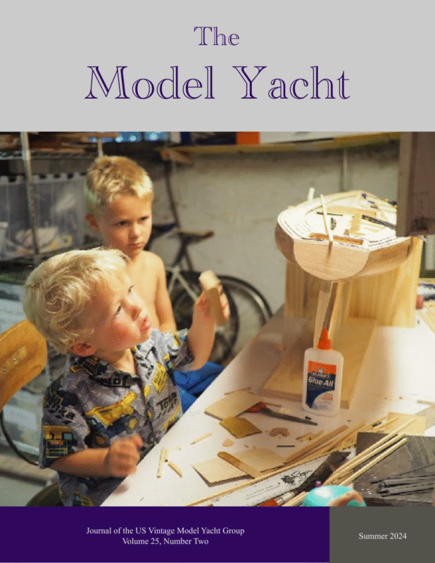
The Model Yacht Summer 2024 The Model Yacht is published three times per year by the US Vintage Model Yacht Group. Copyright 1989 to 2024 by the US VMYG. Reproduction for noncommercial purposes permitted; all other rights reserved. Other copyrights are maintained by the original holders, and such material is used here under the fair use provisions of the relevant copyright acts for nonprofit research and educational purposes. The Layline By John Stoudt Definition: A layline is a straight line (or bearing) extending from the next mark to indicate the course a boat should be able to sail on the one tack in order to pass to the windward side of the mark. (vsk.wikia.com/wiki/Layline) Plans Update Editorial Address: John Stoudt 309 Sundance Drive Chester Springs, PA 19425 We have not yet been able to nd a volunteer to serve as our plans coordinator; however, we have been able to digitize the plans we want to post. These will be added to the plans available on our website https://usvmyg.org/store/plans/. The list includes: On the Cover: The Crew working on Bewitched. See the article on page 24. Membership Renewals: Membership is now being managed on a rolling 12month period. The annual membership fee will be due on the anniversary of your last payment. You will receive an email noti cation leading up to your due date. Please see the “Membership” page at https://usvmyg.org/ memberplans/memberships/ for more information. Additionally, we have the plan for Dale Wenninger’s M Class mentoring program boat, Mentor. This is a modi ed Madcap. This plan will be made available with the entire instructional program in the near future. We also have a partial plan for Roy Clough’s M1, the rst Marblehead class boat designed and built in 1930. How did we come by this? John Snow’s father had the boat, which John now has. On one of his visits to the United States, Graham Reeves began measuring the boat and committing the lines to paper. It is not complete, but it does show some interesting design characteristics that the photographs do not reveal. The board is discussing the best way to make this available. The board is considering ways to provide you the member with additional bene ts. We have a lot of archival materials, some in print format and fi 1 fi fi fi fi fi Requesting a sail number: You can get a new sail number or transfer a registration from a previous owner here:https:// usvmyg.org/registration-2/ Select the class to open the correct form. There is a $7.00 fee for new registrations but no charge for transfers. The class coordinator will contact you to con rm your registration and sail number.
The Model Yacht Summer 2024 other material in digital format. We are going to review what we have and begin to make it available through your portal access. Inside What Does Your Support Do? The Leadership Team……….i The Layline…………………1 Barnacles………………12, 23 A member recently said, “$30.00 is a lot to pay for three Journals per year”. This got the board thinking about “what do your dues ( nancial support) do”? We had never really thought about this in this way. We went back and reread our mission and goals (https://usvmyg.org/ about/mission-and-goals/). This led us to the following interpretation of what your membership and nancial support (dues) do. Grand Old Man of The funds from your support and other sources of income (sale of plans, booklets, investments and other items) allow us to: • publish three issues of The Model Yacht each year, digitally and in print. • publish the journal without advertising. • mail the journal to those who pay for a mailed copy. • continue to develop and maintain our website (https://usvmyg.org). • collect, record, and archive early model yachting items. • support the club that hosts the national regatta with regatta subsidies. • provide construction advice. • provide additional member bene ts, such as free copies of back issues of the newsletter/journal. • assist individuals identify a boat they have. • accept donations as a 501(c)3 organization. • support US VMYG events. • register yachts and maintain class records. • repurpose Journal articles to build out the web site with valuable content. Model Yachting……………20 Thank you for supporting the “Legacy of Model Yachting”. Bewitched…………………24 Beginning Model Yachting Series Jim Linville…………………4 A New Vintage 36/600……..5 Naval Architecture: Lessons 1 & 2………………8 Make a Boat Stand……..…13 Friendship-Rigged Nottingham………………..16 Construction Conversation………………25 Interesting Old Model Yacht Articles……………..34 We will start a new series on Beginning Model Yachting that we will publish in the journal and make them available on the website. It will include potential topics such as: • how to select a boat. • the different types of building: plank on frame, carving, berglass, kit boats. • how to read a lines plan. • rigs and spars. • radio control basics. We’ve included an article from The Model Yacht from 1928 that explains lines plans pretty well (see page 8). If you have other topics that you think should be addressed, please let us know at usvmyg@gmail.com. fi fi fi fi 2
Summer 2024 The Model Yacht Membership Bene ts We are planning to make more member bene ts available. Some of that print material alluded to previously are copies of early issues of The Model Yacht and Model Yachting Monthly. We need to nd a way to get permission to use them, digitize them, and make them available. There is a lot of great historical information at our ngertips that we would like to share. If you have any of this material or other early model yachting materials and would like to donate them to the US VMYG, please contact us. We will inventory the items, place a reasonable market value on them, and send you a letter of thanks for tax purposes. You may contact me (jstoudt309@gmail.com) and/or Chuck Lage (usvmygt@gmail.com). REMEMBER: We are a 501(c)3 nonpro t organization. Photo by Chicago R/C Model Yacht Club 30th Anniversary National Regatta The Chicago R/C Model Yacht Club (www.ChicagoRCmyc.org) and the US VMYG announce the 2024 National Championship Regatta, September 12–15, 2024 (30th Anniversary Year) to be held in Century Park, Vernon Hills, IL 60061 Regatta Webpage: https://chicagorcmyc.org/vintage-regatta-1 Contact the Regatta Registrar: Karen Richmond RichmondKL@Comcast.net or 815-712-6934 If you would like to borrow a boat to sail, contact Ken Young: youngrun@sbcglobal.net Hailing All Members Chuck Lage, our membership secretary, would like to remind us about address or email changes. You may now make these changes yourself via the member portal at usvmyg.org/login/, or you may email him at usvmygt@gmail.com, or send us a letter. We don’t want to lose touch with you! Remember this organization is about you and your passion for model yachting. Do you have a story to tell? Maybe pictures and the history of your collection of yachts? Or maybe the project to build your favorite model? Family stories about how a model has passed through the generations are always great to hear. Please share your story with us. fi fi fi fi fi 3
Summer 2024 The Model Yacht Eight Bells for Jim Linville from the Minuteman Model Yacht Club From the days of tall ships, Eight Bells signi es the end of a sailor’s watch. Time for a sailor to rest.—Ed. Sadly, Jim passed away peacefully on the morning of June 9, 2024, following a brief hospitalization. He leaves behind a myriad of friends and family from the East coast to the West coast, and everywhere in between. Jim had a gregarious personality, and the people he met in his life were quickly drawn into his sphere of friendship and generosity. publication support for their journal, The Model Yacht. He wholeheartedly supported the Woods Hole Model Boat Show. Jim was a lifelong sailor who was passionate about his hobby of building and sailing model yachts. For almost 30 years, Jim maintained a prominent role in the Minuteman Model Yacht Club, teaching and mentoring members, both new and old. Jim also belonged to the American Model Yachting Association (AMYA), a national model yachting organization. With this organization he served as Regional Director, as US1M Class Secretary, and in multiple publication support staff positions for Model Yachting magazine. Without a doubt, the older model yacht designs, with the greater building skills they required, appealed to Jim. The process of lofting, fabricating, and planking were positively therapeutic. It’s believed that he enjoyed building possibly more than he did sailing, because it was hard for him to talk to his friends and sail at the same time. In 2008, in recognition of his many achievements, Jim was voted into the AMYA Hall of Fame. In addition to his participation in AMYA, Jim was avid about building and sailing vintage model yachts. He was also a life member of the US Vintage Model Yacht Group, another national model yachting association. With this organization Jim also provided Jim Linville at the Sue Linville Memorial Soling regatta held by the Minuteman Model Yacht Club. In keeping with his gregarious personality, Jim was steadfast in maintaining the relationships he developed in life. He traveled nationally and internationally to participate in regattas, as much to see old friends, as to sail. Every year, after the passing of his wife Sue, Jim would also pack up several books-on-tape and take driving trips across the country to visit sailing friends, longtime friends, and family along the way. His weeks-long adventures would eventually end in San Diego, CA where he visited a friend from high school before turning around and zigzagging back across the country to visit people he missed on the way out. Jim will be missed as a friend, as a mentor, and as a committed family member. I have a vivid memory from around 12 years ago. Jim and I were battling for last place with our Vintage Ms up at Redd’s Pond. Jim said something like “There are those who sit on the sidelines, and there are people like you and me, we get up and participate” Wise words to live by. I drove home happy that day, with a memory that stayed with me. Thanks Jim, have fun at the old toy boat pond above the clouds. John Storrow fi Is there room for one more? Photo by John Stoudt 4
Summer 2024 The Model Yacht A New Vintage 36/600 Based on a Marblehead 450 Article and photos by Alain Jousse The pandemic came at a time when nearly all of my “ x it later” things were almost done. You know, cleaning and re-soldering the corroded connections, rerouting wires, replacing the frayed sheets, oiling bearings, and taking care of the repairs and maintenance of toy boats. Now was the time to look for a new project. Since we could NOT sail, due to Covid, building was the next viable option, and I had been toying with the idea of building another boat. Some 20 years ago, through a number of events, a series of 19 newspaper articles authored by John Black landed in my lap. This led to the publication of the book Yankee III by Earl Boebert and eventually led to the Vintage 36 class. Because I had played a part in the creation of this Class, I kind of felt an obligation to build one. So, I started thumbing through the back issues of The Model Yacht. In the Fall 2008 issue, page 8, I found the article on “The Delta Class” design. It was an easy build, with good lines. Interestingly, I had used this design before as a starting point for a couple of Vintage Marbleheads and a 10-Rater (9.996). After some research I realized it is a scaled version of the International 110. As I said before, the Delta Class boat is an easy build because everything is cut on the table saw: the sides are plumb, the deck is at, and the bottom is at a 15-degree angle. I spent a few days making the boat and making it watertight, then I took it out for a spin. On its maiden voyage I did NOT like the way she set in the water. It seemed too stern heavy, which led me to think that it needed more body; a square stern would be better. So, back to the drawing board. As it was, I turned the page and noticed the article on the Marblehead 450*, and I studied the plans found on page 12 of the same issue. Voila! It had a LOA of 36 in, which was perfect for a V36. Thank you, Earl Boebert, for making the scale plans exactly 9 in long. That was just right; go to Staples and tell them, “enlarge this 400%”. Magically, ALL of the calculations are done. I started the construction, in my head. What to do? Plank-on-frame or cold molded? It had been a long time since I had done a plank-on-frame. Let me see, there was a 48-in Chinese Junk (some 30 years ago), and the Lynx, a topsail schooner that was 48 in on deck (that was about 20 years ago, and a 5-year project). Then there was another 48-in-on-deck model of a reproduction vessel on the Piscataqua river, in Portsmouth, NH. It was the workhorse of the area, utilizing the tide as the main propulsion and the wind as the auxiliary power. It was used from about 1650 to 1900. It is a “cut-away” model with the port side nished and the starboard side open showing the frames, knees, and the interior construction as in the life-sized vessel. I used the same materials as the life-sized boat. (Working with green wood is interesting.) Cold molding was fl fi fi *Note that the Marblehead 450 is not the same as a Marblehead or our Vintage Marblehead class. It was a precursor to the 50/800 class that had only one restriction – a limitation to 450 in2 of sail area (see https://usvmyg.org/history/ marblehead-history/). 5
Summer 2024 The Model Yacht and were made from ½-in MDF, covered with blue tape, (so the glue would not adhere to them). I like to have a level platform inside for the electronics board, so I used the LWL for that. To make the moulds, I copied the half-breadths in full onto a sheet of tracing paper. After cutting them out, I glued them on to the mould materials, using spray adhesive. That took about a week and a half. Checking twice and cutting once is important, as a screw up here would kill the project. After making the frames, I screwed them squarely onto the building board and made sure they all had the correct bevel. The plans. intriguing, but I am not sure if I wanted to try that at this time (maybe later). So, plank-on-frame it is! Planning the construction took another few days. I wanted to deepen the draft then make a plumb bow and stern, which would give the boat a 36-in waterline. The boat was designed for a ballast weight of 3 1/2 lb. I called Cliff Martin to ask what he was using on his V36. He said that his ballast was around 3 1/2 lb but that he could use a little more (sounded good, don’t reinvent the wheel). So now with a heavier boat and batteries and electronics in the boat, I would need more freeboard. I added 1⁄2 in, but in retrospect, a little more would have been a good idea. The sides are made from the 5/4-in cedar decking material. I cut strips over 3 ft long, a strong ⅛ in thick, to be run through a surface planer later, (both sides—saves on sanding). Then I ripped them to ⅜ in on the table saw. The deck is one sheet of 1/32-in birch ply from balsausa.com. Now with my “full size” plans, I can layout the work and determine where all the stuff inside is going to go and how to anchor it. Also, how much to enlarge the rudder to get The nished hull. to “what would look about right”. I made a soaking tube from a 2-in PVC pipe and used blue Windex as the medium because it To simplify my work, I elected to make the backbone, keel, and mast support in one piece (no joints, no weak points) out of ¼-in birch plywood. I was going to use the same material for stations 4– 7, which would stay in the boat. Stations 0–3, 9, and 10 were for building purposes only Now it’s time to take all this stuff and make it look like a boat. Plank-on-frame is very easy when using green wood as mentioned before. The wood will take bending and twisting at the same time with ease. Let it dry, and it will retain the shape; it’s almost a “cake walk”. The nished hull. fi fi 6
This time sea trials were successful. I planned and made two rigs for this boat, the tallest allowed by the rules, and a gaff rig (just because). I am pleased with the outcome, but I will eventually have to make a proper gaff rig, as the tall rig is a little tender in wind over 5 knots. The gaff rig is a repurposed mast from a Soling 1M, and the sails were cut down from a VM. She likes the short rig and smiles as she is cruising along. Note: Since starting this report, I have made a proper gaff rig, and with Earl’s input, I have redesigned the sail plan, yet to be tested against another V36. At the Enduro in Neeham, MA on Nov 1, 2020, Cliff sailed her for a photo shoot against a DF95; she held her own. I am pleased! Sailing with a DF95. contains a small amount of ammonia, which helps break down bers. I tried a premixed solution of ammonia on a couple of planks before I discovered that it discolored the wood with a greenish tint, and it stinks. Planking a boat is a slow process: two planks a day, one per side. I used TiteBond III and applied the glue using a plastic syringe. All of the boards are edge-glued. It takes time, but you need the strength of each adjacent board where there are no frames, beveling each plank along the way to insure a snug t. Make sure to wipe off the excess glue with a damp rag. Do not let the glue dry, it will bleach the wood. I started at the sheer and moved up, or is it down, the side, stopping at the waterline. Then I restarted at the backbone and, alternating between the two, to meet in the middle, lots of cut, dry- t, plane, sand, dry- t, plane, sand, dry- t plane, sand, for each plank. It is a slow process that can not be rushed, period. This has been a successful project. Anyone can do it, but if you do not try, you will never know if it works. Both Thomas McLaughlin and Cliff Martin can attest to the fact that I have created some “not so great adventures”. Now is the time to start to do some sanding and look and feel for some imperfections. Above the waterline I had to sand until I was happy, below the waterline I had more latitude, body putty works wonders; it will be painted. The electronics are mounted on a removable board, I should have made the hatch a little longer. It only goes from frame 5 to frame 7 and is only 3 ½ in wide. It’s a little tight to move the electronic board in and out. I used a drum winch because the interior is a bit narrow, so the turning block is all the way in the bow, at the end of an arrow shaft. The rudder is probably too large, but it’s easier to shrink it than to make a new one. fi fi fi 7 fi fi Summer 2024 The Model Yacht
Summer 2024 The Model Yacht Naval Architecture for Small Boat and Model Yacht By Thomas L. Lathrop, Sea Scout Naval Constructor Builders: Lessons 1 and 2 This article was originally published as the rst two articles in a series in The Model Yacht. Lesson 1 was published in Volume 1, No. 3, November 1928, and Lesson 2 was published in Volume 1, Nos. 4 & 5, January–February 1929. This rst iteration of our journal namesake started publishing in September 1928. We have copies of Volume 1, Nos 1-6 and 11 & 12. Unfortunately, we do not have issues that include the conclusion of this series. If you have copies of The Model Yacht from the 1929 or any later volumes, please contact us at usvmyg@gmail.com. Also, please note that any prices quoted in the article are given in1929 dollars. Lesson 1 other forms of drawing, as they are applied to our need. In taking up the study of Naval Architecture, our sole aim is to provide the student with a workable knowledge of ship lines and how to use them. No attempt can be made in so short a time and so limited a space to entirely cover the subject. We cannot hope to make Naval Architects out of every person who will follow these lessons. If we are able to provide a workable knowledge of all those funny lines one sees in a drawing of ship lines, we will have accomplished much. There is a vast difference in designing for one’s self or for others, and in copying from the designs of others. Naval Architecture in its advanced forms is one of the most dif cult of engineering subjects. The small boat builder approaches the subject with misgivings. This he may well do, as the subject in the advanced stages will tax the capabilities of an expert engineer. However, there is nothing contained within the elementary portion which should not be mastered by the average person. No attempt should be made by anyone to design until he has mastered the entire subject: To do so will mean only failure. As we advance, you will see why this is so. The Drawing Board As we must have some permanent surface upon which to work, let us consider the drawing board. Perhaps we already have a drawing board; if so, we can adopt our future drawings to this board by changing the scale to t the size of the board. But as most of our later work will require full-size line drawings, and we have no board large enough for these, we will make one. A cheap and handy board may be built up out of most any lumber. It is recommended that several students go together and form a class, thereby gaining the bene t of the thought of a group rather than individuals. In the lessons we deal with the subject as before a class. If the students have had some mechanical drawing, well and good. If not, they will be required to study some good book giving the general outline of the subject. Any school or public library will have many good books from which to gain this knowledge. Perhaps the best way is to interest some good draftsman in your class. We cannot attempt to go into the regular drawing detail. However, an attempt will be made to cover orthographic projection and Fig. 1. A home-made drawing board. fi fi fi fi fi 8
Fig. 1 shows such a rough board. It need not be square on the edges, as all the work of squaring is done by the straight edge “A”. Any good smooth surface large enough and capable of taking thumb tacks will do. In fact, I have used an old discarded door covered with beaverboard or a kitchen table. If the board is to be built up, it might be even longer than shown. As many of the Class “B” sailing models are around 100 inches long, the length might well be 12 feet. However, the width should be kept down and the board placed on horses, low down, and in such a position as to be able to work from all four sides of it. The material used should be stiff enough to prevent any amount of sag when the board is resting on the horses. Fig. 2. Ship curves and spline weights. cardboard is used, it should be of close grain and the nished curve varnished in order to make the edges hard. If of aluminum, the curves should be varnished or painted to keep them from marking the drawing. The purchased curves will in most cases be of celluloid, which is the best material for these tools, but hard to get, and costly. Tools These we will list as standard and special tools. Under standard tools we need: ● One T-square, 36-inch blade. ● One triangular boxwood scale (architects). ● One 30- by 60-degree triangle (larger the better). ● One 30 degree by 60 degree triangle (small 8-in.) ● One 45 triangle (medium, 10 inch). ● One set of drawing instruments. ● Two 4-H pencils. ● One red rubber eraser. ● One box thumb tacks. ● One ne le or sandpaper. About all there is to making these curves is to properly transfer their outline to your material, cut them out, and le the edges smooth. There must be no nicks, humps, or at spots along the working edges. The straight edges will also come under special tools. Two of these will be required. The large one for the edge of the board should be made 1/4 inch by 4 inches by length of the board plus 1/2 the length of the T-square head on each end. The material may be any good hard wood. Maple, oak, walnut or mahogany are the best woods for this. We will also require a smaller straight edge 1/4 inch by 2 inches by 48 inches, which we will use later in our work. Under the heading of Special Tools—I say “special” because in most cases they will not be found at a local stationers, but he can get them for you from any manufacturer of drawing materials on a special order: Foremost are the ship curves. These may be purchased singly or in sets of 121 curves known as “Copenhagen Ship Curves.” Such a set would cost $85. But we do not require a full set. In Fig. 2 I have shown several of the best. If purchased singly, they will average $1 each. But why buy them? In order that you may make these up yourself and thereby save several dollars I have drawn the sketch full size. The Model Yacht has the tracing and can furnish you a blueprint from it. [Unfortunately we do not have access to this full-sized blueprint.—Ed.] I have also shown, in the sketch, two forms of spline weights. These weights can be purchased or made from lead or iron, and are used to hold a exible batten known as a “spline,” which we will use later in laying down and fairing up our line drawings. Do not make these splines yourself. Better results can be had with manufactured splines. Get one 48 inches long of celluloid which lists at $1.10. Do not get maple splines, as they are too stiff for our requirements. Let us consider the building of our board and the collecting of tools as our rst lesson. (Next month we will try and see what this is all about.) The proper material from which to make these curves is a question: I have some made from 1/8-inch black walnut, some of aluminum, and some of cardboard. If ***** fl fi fl fi fi 9 fi fi Summer 2024 The Model Yacht
Lesson 2 In starting the actual study of marine drafting, we should rst determine the points of difference between this form of drawing and ordinary mechanical drawing. In mechanical drawing, we are dealing in most cases with shapes which are based on at surfaces and have one or more straight lines, which form a base from which to work. We are enabled, by an arrangement of straight lines, circles, and arcs, to delineate upon a at surface the exact shape of our object. In most cases the drawing can be so dimensioned that no fullsize layout is required to reproduce the object drawn. Fig. 4. In drawing a wagon tongue, we begin to get into curves. dimensions, reproduce this same box, by thousands. In other words, it is a drawing of straight lines, and any section taken in any direction would consist of a collection of straight lines. In Figure 4 we have a wagon tongue. We might reproduce this by the use of the Isometric sketch alone, as it consists of straight lines and circles, and any section taken at points along its length would be either round or square. In Figure 5 we have a loaf of French bread. How would we go about drawing this, remembering that our drawing must be so well done that another loaf could be made from it? “Can’t be done,” you say? I doubt if it can either—in a baker’s shop—but a drawing can be made, and if enough sections are Fig. 3. Drawing of a box, to illustrate projection in straight lines. This is not so in ship drafting. Here we are dealing with a constantly changing collection of curves. Before a reproduction of the design can be attempted, an exact, full-size layout must be made of each curved shape. This is true of a row boat or of an ocean liner. Just where mechanical drawing ends and the art of marine drafting begins is somewhat problematical. Marine drafting, being a special form of descriptive geometry, is really only mechanical drawing in a special form. So that we may get started with the least trouble, let us take up three distinct objects, and see how we would have to draw them in order that they might be reproduced miles away from the place where they were designed. First let us take a box—Figure 3. Now, there is not much to this box. It has a bottom, two sides, two ends and no top. We see that it is somewhat longer than it is wide, and that it is deeper than it is wide. We might, by the addition of a few Fig. 5. Drawing of a loaf of bread. Beginning now to get into lines approaching those of a yacht’s hull. fl 10 fi fl Summer 2024 The Model Yacht
Summer 2024 The Model Yacht taken and details shown, a modeling artist might reproduce a loaf in modeling clay which would be very close to the original. lend themselves to dimensioning, and that we have used but very few straight lines, and these only as witness lines, to determine where we took the sections. In other words, we have a drawing of contours or curves, a gure on which no two points of its surface can be said to be the same. Now, in order to make a drawing of this loaf of bread, we will be required to cut up the loaf into many sections. And as we do this, we must place each section on our drawing paper and trace around it; and each section must be so placed on the drawing as to be in its correct relation with every one of the other sections. When we have nished the drawing we nd that we have a series of curved lines which would not It is with this type of drawing that we must deal in naval architecture. Unlike the bread, however, both sides of a hull are alike. We therefore need to draw only one of the halves of our boat in order to have an exact record of its entire shape. The basic thought to keep in mind is: That so far as the hull or shape determining lines go, we are dealing with a solid body of irregular shape. In order to x in our minds some of the lines which determine the shape of the hull, let us take a set of lines, and take them apart. In Figure 6 we have the lines of a small schooner. You will note that there are three views—a pro le or sheer plan, a half-breadth plan, and a body plan. In the pro le we are looking at the boat from the side; the outline in this view is the exact shape of the hull if we were to cut directly through the centerline lengthwise. It is with the body plan that people have the greatest trouble. This is due to the fact that they see too much of it. Cover up half of the lines, or all on the left of the centerline, and you will see that you have contours or shapes for all of the stations from the bow as far back as the widest or midship section. Now cover up the lines on the right half of the view, and we have contours of all of the sections from the midship station aft to the transom. You Fig. 6. The lines used in reproducing the hull of a yacht. fi fi fi fi fi fi 11
Fig. 9. Buttock lines. Fig. 7. Station lines. will also note that in each case these stations are numbered and that these numbers are shown in their place in each view. In the half-breadth plan we have a view looking at the hull from the bottom. Here we nd long sweeping curves made by the waterlines. Diagonals and a curve of areas are also shown: these will be taken up later. In Figure 8 we deal with the waterlines. These are lines showing the shape of the hull as it rests in the water, i.e., if we were to push the hull down into the water or raise it up a distance corresponding to the vertical space between the straight lines shown in the sheer plan, we would have a shape formed by the meeting of the surface of the water and the side of our ship, which would look like the section which we have removed from the model. These lines will be found in contour in the half-breadth plan. In Figure 9 we have sawed the model along one of the buttock lines. These are lines which show as straight lines in the half-breadth and body plan and as contours in the sheer plan. The service performed by these lines will be explained later. Now the only way one can understand all the jumble of lines shown on a ship line drawing, is to take a pair of dividers and transfer widths and distances from one view to the other. Do this with Figure 6 or some other set of lines, keeping in mind that, insofar as the lines go, you are dealing with the outside shape of a carved block of wood. When we have the general position and names of these several groups of lines xed, we shall attempt to lay down a set of lines from some de nite design. (To be Continued) Fig. 8. Waterlines. Perhaps the best way to picture these several forms of lines is by the use of a half model of the hull. In Figure 7 we show the model cut across at right angles to its center line. The sections removed will correspond in shape to the contours shown in the body plan, and the saw cuts would show as straight lines in our pro le view. Barnacle Stop Loss Bags—Does your nish start to get funky in its original container after you have begun to use it? And do you often throw away some of that expensive nish. Well, no more! These bags maintain your nish’s quality from start to nish. Enjoy consistent results by pouring the remaining nish into one of these clear bags and squeeze out the extra air. Plus, they’re cost-effective and help you protect the qualities of your expensive nish. They are readily available on Amazon. fi fi fi fi fi fi 12 fi fi fi fi Summer 2024 The Model Yacht
Summer 2024 The Model Yacht Make a Pondside Boat Stand Article by TMY Editorial Staff. Photos and drawings by John Stoudt Star Sharpie Jr. in a travel stand. There are many types of boat stands you can make for a model yacht. One necessary stand is the travel/ work stand. When building or restoring a model yacht, this stand is the rst thing you should make. It serves nicely as a work stand and is great for traveling with your boat. It folds up and is easy to transport with all of your other “stuff”. Although it could be used as a display stand, it is not intended for display because it is not very attractive. Materials ● ● ● ● ● ● ● ● ● Four pieces of 1⨉2 hardwood (length depends on boat size) Two pieces of ¼⨉2 hardwood (length depends on boat size) Two ¼-20 stainless steel carriage bolt Two ¼-20 stainless steel nut Two ¼-in stainless steel washer Sixteen ¾-in #8 stainless steel at head wood screw Four #8 stainless steel nish washer About 36 in of polypropylene webbing Marine nish The most conveniently available lumber is 1⨉2 and ¼⨉2 poplar from a box store like Lowes. These sizes come in 24- and 48-in lengths, and they will make a boat stand strong enough to hold a boat the size of an International A boat. The hardware is available in stainless steel in small quantity packages from the same store. Although brass and bronze are an option, they are much harder to nd and rather expensive. The strapping can be acquired in long lengths from Amazon. We have been using sail ties (polypropylene webbing), which come in a lot of great colors, for the hull support straps. Tools ● ● ● ● ● ● ● ● ● Awl Assorted drill bits Sandpaper and sanding block Circle template or compass Countersink bit Drill press or electric hand drill Handsaw, bandsaw, jigsaw, saber saw, chop saw, or table saw Screwdriver Try square or combination square Rung attachment. fi fi fl fi fi 13
Summer 2024 The Model Yacht Because the model yachts we work with vary in size signi cantly, the lengths of the legs, rungs, and support straps will vary from stand to stand. Here are some general guidelines: ● The legs will be the same length as the overall height of the hull from the bottom of the keel to the edge of the deck. ● There is one long rung and two short rungs: o The long rung will be the horizontal length of the keel from the forwardmost point of the leading edge to the aftermost point of the trailing edge plus 9 in. (So, if the horizontal measurement is 8 in, add 9 in for a length of 17 in). o The short rungs will be the horizontal length of the keel from the forwardmost point of the leading edge to the aftermost point of the trailing edge plus 7 7/16 in. (So, if the horizontal measurement is 8 in, add 7 7/16 in for a length of 15 7/16 in). o Note: The difference in lengths between the long rung and the short rungs is twice the thickness of the legs (¾ in) plus 1/16 in for space. Procedures: 1. 2. 3. 4. 5. 6. 7. 8. Cut four pieces for legs of 1⨉2 to length based on the overall height from the bottom of the keel to the edge of the deck. Cut two pieces for short rungs of ¼⨉2 to length based on the formula above. Cut one piece of for the long rung of ¼⨉2 to length based on the formula above. Round both ends of the four legs. Use a circle template or compass to draw a 3/4-in radius on each end of all four legs. Cut the ends using the saw of your choice. A bandsaw with a narrow blade works very nicely. Sand the rounded ends of the legs smooth and round of all edges. Drill a 17/64-in hole dead center along the length and width of all four of the Leg layout. The 1 ½-in wide face of the leg is shown. legs on the 1 ½-in wide face (width). Sand the rungs smooth and round all of the edges and corners. Drill two 7/64-in clearance holes in each end of all three rungs and countersink for a #8 stainless steel at head wood screw as illustrated. Note: How do you know when a countersunk hole is deep enough? Start by drilling down a small amount with your countersink. Hold the screw head on the top of the countersunk hole. The screw head should just match the perimeter diameter of the countersunk hole. If it does not, drill deeper a little at a time. Once you have determined the correct depth you can set the depth stop on your drill press. 9. Take two of the legs (these will be your internal legs) and place them side-by-side on their edges and line up the ends. Draw a line across each leg 2 inches in from both ends. 10. Take the other two legs (these will be your long legs) and place them side-by-side on their edges and line up the ends. Draw a line across each leg 2 inches in from one end. 11. Mark each leg and rung with the letters A to F. Place the notation in a location that will not be seen when the stand is completed. (See letters noted on the rung assembly illustrations). Note: You are doing this because you will assemble and disassemble the stand, and then reassemble it. fi fl 14
Summer 2024 The Model Yacht 12. Take one set of legs and move them about 12 in apart. Using a try square, align one rung ush and square on the outside of a leg and mark the two holes on the leg with an awl. Repeat this process for each set of holes for each rung. Note: The short rungs are attached on opposite sides of the legs. Long rungs. Short rungs. 13. Drill a 3/16-in pilot hole in all 12 locations on the legs. 14. Assemble the leg sets with ¾-in #8 stainless steel wood screws. 15. Place the legs sets together as pictured and insert the carriage bolts from the inside out and place a washer and wings nut on the carriage bolt. Lightly tighten the nuts and see if the legs “rotate” easily. 16. Now mark the top outside edge of each of the four legs for the screws that will hold the straps on. Mark down from the top edge 1¼ Leg rung detail. in and place a mark at the center of the leg with an awl. Drill a 3/16-in pilot hole at each of these locations. 17. Cut two pieces of webbing and heat seal the ends with a grill lighter so they do not fray. The length of the webbing should be 1½ times the height of the boat (already measured as the length of the legs) plus 3 in. For a boat that is 12 in from the deck to the bottom of the keel, you will make the legs 12 in long and cut the webbing to 12 in ⨉ 1½ + 3 in = 21 in. 18. Fold one end of the webbing back on itself 1 inch and punch a ⅛-in hole half an inch back from the end, centered on the webbing. Fold and punch the other end and on the other piece of webbing. 19. Place a nish washer onto a 1-in #8 stainless steel at head wood screw and insert the assembly into the two punched holes on one end. Insert the screw into one of the pilot holes on the top of one leg and screw into place. 20. Attached the other end to the mating leg. 21. Repeat on the other set of legs. Webbing detail. 22. Take the entire assembly apart and apply multiple coats of a waterproof nish to protect the stand. Make sure to sand lightly between coats of nish to ensure a nice smooth nish. 23. Assemble your stand. CAUTION: Because every boat and its underbody shape are di erent, the nal dimensions may vary slightly from those suggested. Some early M class boats have very di erent shapes fore and aft that could cause the length of the straps to be di erent. You can double check this before cutting the second strap. fl ff fi ff ff fl fi fi fi fi 15
Summer 2024 The Model Yacht Article and photos by Gudmund Thompson The Deck This is the next article in a series detailing the construction of Gudmund Thompson’s Friendship-Rigged Nottingham. You can see earlier articles in The Model Yacht: “Running Backstays” in Volume 23, Number 2, and “Computer Radios” in Volume 24, Number 1, and “Below Deck” in Volume 25, Number 1. — Ed. The Nottingham kit, from Alan Horne, came with a nicely laid out deck (with lines for planking and pre-cut hatches), but I opted to do things a little differently. My goal was to produce a hull that could be tted not only with the ve-sail Friendship rig that it now carries, but also, perhaps, a rig that sports a modern square-topped mainsail with a 130% genoa, as an example. The Nottingham under sail with the Friendship Rig (left), and the deck during the building process (right). The plan I came up with included a “jib track” that goes most of the way from the bow to the mast step and provides mounting options for a forestay and multiple headsails (including a jumbo jib). There is also a track on each side of the boat that starts at the mast and stretches well back to cater for the adjustable sidestays and provide movable anchor points for the head sails, be they multiples or a genoa. The plan also included anchor points for the running backstays and (yes, I know it is redundant) a backstay. Preparation I ensured that the deck-support structure was in place before working on the actual deck. This included: ● building and installing the two ush- Before the deck could be worked on, the deck support structure needed to be installed (left) and the through-deck tting positions established with-the-deck hatches, (right). ● designing and installing the strengthening components for the front and side tracks, and fi fl fi fi 16
Summer 2024 The Model Yacht ● waterproo ng the below-deck wooden parts by coating them all with Mod Podge (normally used in decoupage, but readily available and easy to apply). Planking With the deck support structure complete, I temporarily attached the sub-deck to the hull and installed all of the through-deck ttings. Then I removed the sub-deck, covered the bottom of it with masking tape (to hold the hatches in place and to keep glue from leaking into unwanted places), and secured it to a piece of melamine-coated shelving. This made the planking and nishing very much easier. The Compass Rose was positioned on the deck, and the planking scheme was developed. The planking was actually pretty straightforward. I positioned and installed the pre-assembled Compass Rose, cut the planking strips to size, rubbed the edges of the planks with an HB pencil to give them some de nition, and installed them following the planking plan. With the hatches in place, the underside of the deck was covered with masking tape (left). The deck was then turned over and nailed to a piece of melamine shelving in preparation for planking. To adhere the rose and planks, glue was applied to the back side of the pre-assembled rose and sheets of veneer. When dry, the planks were cut out. fi fi fi fi 17
Summer 2024 The Model Yacht Glue was also applied to the sub-deck and allowed to dry. Unfortunately, a sloppy application (left), necessitated scraping away some excess glue before the planks could be applied. To adhere the Compass Rose and planks to the sub-deck, I used Titebond III as a contact cement—activated by heat. The process was to coat a fairly large section of the deck with the glue and to let it dry. Similarly, both the Compass Rose assembly and the veneer sheets that made up the planks were coated with glue (before the planks were cut out) and allowed to dry. Then, one at a time, the Rose and planks were held in position on the sub-deck and heated with an iron until the glue activated. As a nal step, a wooden block was set in place to absorb the heat as the glue set. Deck Finishing Before the deck was removed from the “shelf,” I nished it with spar varnish, 30 coats, initially diluted 4:1, transitioning to full strength at the end, sanded every ve coats. A bit of polishing and the deck was ready to be prepared for hull attachment. These preparations included: ● ● cutting the hatches free, clearing all of the through-deck openings, ● trimming the deck to t the hull, ● sealing the underside of the deck— again with Mod Podge. Once the deck was free from the shelving, trimmed to size, and glued to the hull, I tackled the installation of the three tracks and mast step that I wanted to install ush with the deck. This involved the acquisition of a very nice hand router and some very careful hand work. With the tracks (and the remainder of the through-deck components) installed, all that remained was the fabrication, With the glue dry, one at a time, the planks were trimmed to shape, then positioned and heated to activate the adhesive. installation, and varnishing of the gunwale. fi fi fl fi fi 18
Summer 2024 The Model Yacht With the hatches cut out, the deck was glued to the hull (left) and the masking tape removed (right), it is almost nished. Almost done (left) and varnished (right). Next, the Sail Rig At this point, I had a very nice looking boat, but without a sail rig. I will deal with the development and fabrication of those components in the next, and nal, installation. A router plane was used to produce the grooves that the tracks and the mast step required to sit ush with the deck surface. After a little trimming of the deck, and roughening of the hull (left), and the gunwale was installed (right). You can see the ush t of the mast step. fi fl fl fi fi 19 Finally, with the gunwale varnished and the deck polished, the through-deck hardware was installed.
Summer 2024 The Model Yacht Cecil Adams: The Grand Old Man of Model Yachting by Graham Reeves I rst met Cecil (some called him Charlie.) in 1960 at the M Nationals at Dovercourt. By then he was 73 years old. I’d rst heard of Cecil Adams in January 1959 when I bought a partially completed Marblehead from fellow Bournville club member Joe Meir. This was a modi ed Foxtrot which I called Bolero. The hull was designed and built by Cecil. Joe, like Cecil in his Naval Uniform during World War I. Cecil, was also keen on the “Tucker Championship in 1914, He also played for Norfolk Duck” Marbleheads. After watching my boat at County. Dovercourt, Cecil advised me to take one pound out of the lead n. I followed this advice, and in 1962 I He married Abigail Eliza Symonds in 1911 at Great won the Marblehead Nationals held at Fleetwood. Yarmouth. They lived at 71 Upper Belle Road Great Yarmouth. She passed away in 1969. They had one th Cecil Frederick Adams was born on 13 January son and two daughters. Gerald Alfred Adams was 1887 in Gorleston on Sea Norfolk. His father was born in 1912 and passed away in 1991. Marjorie Henry Adams, 54, and his mother was Felicia Laura Evelyn Adams was born in 1915 and passed away in Adams neé Rushmer, 42. Cecil’s father was the 2002, and his second daughter, Hilda Maud Adams, skipper of the YOUNG ODD-FELOWS boat when was born in 1919 and passed away in 2010. he drowned in the Yarmouth Roads in 1898. (Yarmouth Roads is a coastal feature in Norfolk that On the 10th of March 1921 he departed from was used by merchant and naval ships as an Southampton on the RMS Aquitania bound for New anchorage or roadstead off Great Yarmouth). York. His wife and family chose not to go with him. He already had a brother in the US with whom he In his younger years he played football for Gorleston had arranged to meet. His con rmed destination on Football Club (FC) winning the Norfolk Junior Cup. the ship’s manifest was Rochester, NY, on the banks He then moved on to Yarmouth Town FC known as of Lake Ontario. From there he eventually traveled “The Bloaters” (a smoked herring) and played centreon to Chicago, probably by train, and found half and Captain. When he was Captain, the Bloaters employment working as a carpenter and joiner. He won their rst Norfolk and Suffolk League fi fi fi fi fi fi 20
Summer 2024 The Model Yacht Model Yacht Club sailing his yacht Tetrach on the Ogden Park Lagoon. In 1929 he won the Midwest A class Championship with a boat he built himself. In 1931 he returned home and joined the Nelson Gardens Model Yacht Club in Great Yarmouth. During World War II he worked at Lathams boatyard in Potter Heigham building wooden Motor Torpedo Boats as well as being a member of the Home Guard. His last job was working for Lacon’s brewery in the maintenance department prior to his retirement. We assume he retired in 1952 at the age of 65. The 1926 Annual Miniature Regatta at Ogden Park Model Yacht Club. After the Second World War, he returned to model yachting. The rst record of him sailing in a National Championship was the 36R Nationals in 1948 that was held at Dovercourt. He sailed a Duck 36 by the name of Donald Duck III K563 and nished in rst place. The boat was was introduced by a friend to a Model Yacht Club there. In Chicago he lived very close to a model yachting lake and club. Within 2 years he was winning most races with boats he built himself. In 1926 he won the Annual Miniature Regatta staged at the Ogden Park Walter Grint sailing a Pahie at the Norwich clubs sailing water. Chicago Tribune (Chicago, IL): 1 Nov 1926 fi fi fi 21
Summer 2024 The Model Yacht Foxtrot pro le. Gigi painted in Foxtrot’s colors. More Pahies followed including Yochabell owned by Terry Todd from Scotland and Bownor owned by Mr. Bowkett of the Bournville Club. In1954 he teamed up with Walter Grint of the Norfolk and Norwich Club sailing the Marblehead Foxtrot K927 that was designed by Cecil. This earned him another Championship win. Foxtrot body plan. designed by HB Tucker and built by him. He continued building model yachts and received orders from all over the UK, in particular for his Marblehead designs Pahie and Foxtrot. In 1951 he sailed Ida Duck K216 in the Marblehead National Championship nishing in 5th place. In 1953 he won the Marblehead National Championship sailing his yacht Pahie K267. This was a boat he had designed and built himself, probably before World War II. Cecil continued to sail with Walter Grint acting as his mate well into his seventies. In 1958 he built two identical yachts based on his Foxtrot design but modi ed slightly. One was sold to Len Maskell of the Leeds and Bradford Club. She was called Gigi and was registered with the number K1187. The other was sold to Joe Meir of the Bournville Club and was bought by me partly nished in 1959. I called her Bolero, and she was registered as K1195. In 1962 she was the rst Adams-designed boat to win a National Championship without Adams’s involvement. After Foxtrot, Cecil designed Waltz K1292, which was another modi ed Foxtrot design. This one was built by fi fi fi fi fi fi 22
Summer 2024 The Model Yacht Dovercourt club, and Helmida for himself to name but a few. He also designed a 10-Rater based on his Foxtrot design. At least two of them are known to exist. One of them is owned by David Bell from the Hampton Court Club, and the other was acquired by Martin Bandey. He passed away on 20th June 1975 at the Northgate Hospital, Gorleston on Sea, at 88 leaving a son, two daughters, ve grandchildren, and three greatgrandchildren. To carry on the family tradition, each of his three great-grandsons received a model yacht designed and built by himself. The last one was completed just before his death. Cecil building one of the many Foxtrot Marbleheads he built for fellow model yachtsmen. The yacht on the workbench may have been Eida Duck K435, which was a Duck designed and built by Cecil. The photograph would have been taken in the late 1950s or early 1960s. Walter Grint. As previously mentioned, I won the 1962 Marblehead National Championship with Bolero; Ken Roberts won the same race the following year with Fandango. These successes caused a building frenzy of Foxtrots that included at least two built by Arthur Levision, which were named Pinky and Perky for Graham Wyeth and Chris Edmondson. More Foxtrots he built for fellow model yachtsmen included Tempest for Alan Bell of Fleetwood, LilHilda for Don Bush of Leeds and Bradford club, Stormalong for Doug Tomlinson of Harwich and A ship in the harbor is safe, but that is not what ships are built for. — John A. Shedd — fi 23 Barnacle
Summer 2024 The Model Yacht In Pursuit of “Good Enough”: Building a Vintage Marblehead during Nights and Naptimes Text and photographs by Marten Beels The US Vintage Model Yacht Group offers some excellent resources for building and restoring vintage model yachts. There are examples of exquisite craftsmanship with beautiful nishes, historical examples showcasing traditional construction techniques and materials, and boats built with extra attention to lightweight construction to be competitive in races. But this article is not about one of those types of boats. This article is about two things: what I learned from the mistakes I made along the way and the challenges of nding the time to build one involving my two young sons in the process. When I read Earl Boebert’s article “Until You Get it Right” (https://usvmyg.org/boats/constructionmethods/until-you-get-it-right/), the quote from Winston Churchill jumped out at me. Although I’m not near retirement, I can very much relate to this sentiment: “There really is no time for the deliberate approach … We must not be too ambitious. We cannot aspire to masterpieces. We may content ourselves with a joy ride…” I found that quote to be very relevant to the process of building a wooden boat and involving my sons. I have two sons, a 5-year old and an 9-year old, so I have very little time each day for, well, just about anything. My day starts with a circus, and it is The rst sail at the Chester Springs Model Yacht Club with help from John Stoudt. fi fi fi 24
Summer 2024 The Model Yacht Bewitched plans. These are available from the plans store: https://usvmyg.org/store/plans/traditional-marblehead/ shenanigans all the way to the end. They’re wild and inquisitive and want to be involved in whatever they can get their hands on. I want to enable and encourage their curiosity, so I’ve learned to involve them in my hobbies as much as possible. Construction Advice This is an email conversation between Marten and John Henderson, one of the volunteers who answers construction questions for US VMYG. You can contact someone from the Leadership Page or through the website at https://usvmyg.org/construction-help/. Working with my hands and making things is a core part of my identity, I derive an immense amount of satisfaction and enjoyment from the creative process of making an idea into a real thing. I hope to pass on some of this joy to my children as well. Although they’re too young to really appreciate the details of boat construction, I do think that they’re soaking up the idea that you can make something with your hands, and it is fun. Marten Beels: Thanks for being willing to answer questions, I’m sure that I’ll have a lot, like how to make the rudder hinge and control linkage. Hopefully by the time I get to that point I’ll be able to come out to the pond and see some other boats live and close up. *********** John Henderson: I’m also happy to help. The Bewitched looks like a nice boat and should not have any particular quirks in its building. Since you mentioned the rudder speci cally, I o er a couple of thoughts: For the case of this particular rudder pro le and hull section, I’m not sure that I understand the bene ts of a rudder post slanted as drawn, and I can see some disadvantages (complicates getting the ideal bellcrank/servo geometry; rudder de ection has a tendency to try to sink the stern). I would consider making the rudder post perpendicular to the waterline. This would also make it easy to enlarge the movable area of the rudder. By class rules, you are allowed to do this as long as the xed skeg is at least 50% of the area of the movable rudder. Many of these older designs were conceived for freesailing, which makes them good sailers, but the Photocopies of the lines drawings glued to ⅛-in plywood for the frames. fi fi ff fi fl fi 25
Summer 2024 The Model Yacht rudders were sized for straight-line sailing, not the maneuverability we expect for R/C. Just be sure that the rudder does not extend aft of the transom. *********** Marten: Also, I’m trying to decide if I should rabbet the backbone. Was it done that way in the past because of the adhesives? Most modern examples I can nd now look like they don’t rabbet the backbone. Or maybe just rabbet the front stem piece? *********** John: I don’t rabbet the backbone. For that matter, I generally don’t rabbet the stem either, unless I just want to show o that I made the e ort. For traditional construction of full-size boats, the rabbets (and other tricks like stopwaters) were used for strength and to give more area for swelling to achieve water-tightness at the tricky juncture of the keel timber and garboard plank (which often had lots of twist and shape). I don’t think models need all this. Huw and Wim (ages 2 and 6) helping to remove the frames. Photo by Rebecca Beels On the other hand, if you want to impress us all with your craftsmanship, do a good job on the rabbets and nish it bright so that we can see. *********** Marten: I think I’m starting to notice that edge set towards the rear of the model already. It isn’t much, but you’re right, the next few planks will each have quite a bit more. These are 5/32 by ⅜ in, so far that seems like a really good size. I’ll have enough thickness to be able to sand to shape. I am using hot water at the rear to handle the twist, and that’s working. *********** John: FWIW, I usually cut my planks to a cross section of ⅛ by ⅜ in, and I usually use western red cedar, so my bending is somewhat easier. On the boat I am now building – a Vintage 36 with a Jboat-like hull – I used ⅛ by 5/16 in because some of the bends are tighter. Hot water helps. Another trick, which works on cedar but which I haven’t tried on mahogany, is to heat the wood with a paint stripper heat gun, being careful not to scorch. Clamp one end, apply the twist/bend where needed, and hold with heat applied for a minute or so. At least with cedar, you can feel the wood “soften”. Hold for a minute or so while it cools. This is just less messy than water. *********** Marten: What about the deck structure? And what size and location of hatches do you recommend? My 9-year old son is old enough to help with sanding and make his own creations out of scrap wood. When he is involved, it is hard to take the “deliberate approach”, and the result isn’t a masterpiece, but there is a lot of joy. The past few years we had been building rockets, which is a very good activity for a young kid, but it doesn’t take long before the basement lls up with cardboard tubes, ns, and other cylindrical objects with pointy tips. I wanted a “meatier” project, Planking in progress. fi ff fi ff fi fi 26
Summer 2024 The Model Yacht *********** John: Deck structure: I’m sure that the center of gravity is marked on the plans. The main hatch should be located to allow the main radio weight (sail servo and batteries) to be balanced over the CG. The only complication is to make sure that you have provided a useable place for each sheet to pass through the deck and reach the servo arm. Also make sure that the hatch cover does not interfere with the boom vang. I think that a minimum size for the main hatch for reasonably comfortable access is 3.5 in wide and 5 in fore-aft. If you have more dexterous ngers than I, you might get away with a little smaller, but I don’t recommend it. On the other hand, bigger hatches are never good from a waterproo ng standpoint, so don’t make it wider than necessary. Huw gets a chance to help smooth out the planking and make some sawdust. After many weeks of planking, this was a satisfying milestone. The rudder servo may be in the same hatch with a long push-rod, or it could be in a separate and much smaller hatch well aft near the rudder. I like the rudder post tube to come up all the way through the deck, with the rudder arm on top of the deck (and perhaps unattractively visible). In this way, there is never a problem with water leakage up the rudder tube. Others prefer to keep the rudder arm below deck for a cleaner appearance, and they claim that a well-greased rudder tube, with grease replaced at intervals, does not leak. Your choice, but the approach to rudder control must be worked out before the deck goes on. something that would take more time and require puzzling through design details. It clicked one afternoon while I was canoeing around a lake by my parents house, chasing a small model sailboat. I knew that I wanted to scratch-build an R/C sailing boat out of wood. From there, it didn’t take long before I found the US VMYG and started looking through the Vintage Marblehead plans. While I’m glad to have my sons down in the basement with me, it’s virtually impossible to make any real progress on the boat with either one down there. My oldest likes to sand, cut things, and paint. My youngest likes to glue things, stack blocks, and play with hardware. So most of my opportunities to work on the boat are either late at night or during brief, stolen moments on the weekends. Because of time constraints, completing any project is a challenge. I make the main hatch framing fairly robust, because I use the hatch as a carrying handle. I think ⅜- by ⅜-in or maybe ⅜- by ½-in cedar frames are adequate. They are glued to the hull frames. The deck goes over these frames. After decking, I install thin plywood sides (1/16 in) to the frame openings, extending ~⅜ in above the deck. The hatch ts tightly over these sides. I picked out the plans for Bewitched simply because it looked like a fun boat. It wasn’t as sleek and fast looking as some of the others; rather it even looked comically fat and bulbous, but that had a certain appeal to it. So I bought the plans and jumped head rst into a bigger project than I realized. Build the hatch cover by wrapping the sides of the hatch temporarily with plastic wrap or thin tape and clamp each cover piece over this wrap while gluing the cover together. The wrap prevents gluing the cover to the hatch frame. Fortunately, I had many good resources available. I consulted Ivor Walton’s beautiful and illustrative photos in his Madcap book, Steve Deligan’s Vintage Marblehead book, some other PDFs from the US Other than the hatch, I think the deck structure can be fairly minimal. I include the deck beams when I cut out my frames, so I have one deck beam per frame. Probably don’t even need this many for fi fi fi fi 27
strength, but they are helpful in de ning the compound curve of the deck (bent athwartships and also fore-aft) – whether you are planking the deck or using a plywood sheet. *********** Marten: It occurs to me that installing hatches means that the king plank is not continuous from the front to the rear. Is it ok to just butt the king plank up against the deck beams? Or is extra reinforcement bene cial? I’m mainly thinking of some vertical support beneath the mast, for example. *********** John: Yes, hatches mean that the king plank cannot be continuous. I usually make “ring frames”, so my deck beams are part of the hull frame. The frames are permanent parts of the structure. Are you using removable frames, and then installing separate deck beams? It is probably best to notch the king plank into all the deck beams, including the ones that de ne the hatch opening. There will also be longitudinal pieces that de ne the sides of the hatch opening, and these can butt up to the deck beams, or be notched. Generally I use butt joints and then reinforce them with triangular gussets that will be hidden below the deck. The deck planks go on top of all this, so they also reinforce the joints (and my gussets may be unnecessary). Deck beams in place. VMYG website, and exchanged many emails (and a few phone calls) with John Stoudt and John Henderson. In the introduction to Steve Deligan’s book, he writes a caution that you (as the builder) may reach dif cult points in the construction where you’ll want to “punt”. I certainly did feel that way a few times—he was right! This article is not about the best way to build a boat, but rather describes my process of guring out what to do, making mistakes, and trying to x them. (See the side bars for some of the very helpful responses from John Henderson.) After the deck is planked, I add the actual hatch sides – generally made of light plywood (say, 1/16th inch) that rise about ⅜ in above the deck. The hatch cover ts tightly over these sides. My rst major error came when it was time to berglass the exterior of the hull. I had some experience berglassing rockets and R/C airplanes, but I always put some kind of vertical support below the nominal position of the mast. Not sure it is necessary, but it makes me feel better. I usually do this by leaving a central vertical segment in the ring frame (or frames) nearest the mast. The other frames are completely cut out in the center. *********** Marten: As for waterproo ng the inside of the hull, what are your thoughts? Thinned epoxy? Unthinned epoxy plus berglass? *********** John: For the inside of the hull I generally apply a coat of epoxy full strength, i.e., without any thinning. Epoxy’s water resistance depends on coating thickness. I think one coat is generally enough on the inside, but I might put a second coat on the areas near hatch openings that might actually get wet. Depending on how satis ed I am with the An aluminum tube is epoxied in place for the rudder. fi fi fi fi fi fi fi fi fi fi fi fi 28 fi fi Summer 2024 The Model Yacht
Summer 2024 The Model Yacht strength of the keel-to-hull attachment, I may put a layer of 2-oz berglass on the inside between the frames in the region of the keel. The underside of the deck is a slightly more interesting problem. If you make a plywood deck, then just epoxy-coat it and glue it down. But if you make a planked deck, as I almost always do, then the “best” thing to do would likely be to epoxy-coat each plank as you are gluing it to the deck beams. This, however, wastes a lot of expensive epoxy, and I’m cheap. I think it is entirely adequate to coat the underside of each plank (as you are installing it) with one of the water-resistant versions of Titebond yellow wood glue. This is easy (you can spread it with your nger with no health hazards), inexpensive, and (my opinion) adequately water-resistant for the underside of the deck. I generally coat the top of the deck with a couple of coats of epoxy after sanding, same as the hull. *********** Marten: Where should the jib rack go, point A or point B? *********** John: The jib rack could be attached at either your point A or B. My personal preference would be Point B, so that the pivot point for the jib is something like 25% aft of the forward end of the jib boom. This makes the jib “self-vanging”, meaning that the aft end of the jib boom does not lift going downwind. A complication, however, is that there can be too much downward force on the leech of the jib, preventing a proper lu curve that matches the curve of the main. The solution to this is a “jib topping lift” running from the aft end of the jib boom up to where the jib stay attaches to the mast. This topping lift is tensioned enough to make the jib’s leech curve properly. But this is not entirely benign – sometimes this topping lift can snag on the spreaders. The trick is to adjust everything so that there is enough tension on the jib topping lift to keep it from snagging. This probably sounds messier than it is in practice. Let me know if this isn’t clear, and I’ll try to nd or take some photos. *********** Marten: What is di erent between a rigging design that uses a forestay, and one that doesn’t? *********** John: You could probably get a variety of opinions on forestays, so I’ll give you mine: A forestay may o er some minor convenience when you are assembling the boat before sailing — you can We take advantage of some beautiful spring weather to work outside and t the rudder in place. this was probably the largest berglassing job I’d attempted so far. The wetting out process went well. The 1.5-oz cloth laid down nicely, and everything looked good when I went to bed that night. However, I knew I had a problem when I came back 24 h later and the epoxy had not fully cured. I attempted baking it with some extra heat, but I knew that it was in vain because I had made a mistake with the mixing or ratio of part A to part B. I was despondent over this mistake and feared that my entire hull was ruined. I had to set it aside for a while as I was too disappointed to be able to deal with it. I thought about Earl Boebert’s rst hull “… a blob of epoxy with sticks of wood running through Wim checks to see if the deck lines around the stern are fair. “Needs more work here, Dad!” fi fi fi ff fi fi fi ff ff 29
Summer 2024 The Model Yacht support the mast before you try to rig the jib. But after the set-up, I think the forestay just adds weight, albeit a trivial amount. I generally don’t use a separate forestay. I mount the jib on a lu wire inside the sleeve on the jib (Rod Carr builds his jibs that way), and I tension that lu wire to set the sag to be whatever I think is right. The tension on the lu of the sail itself should be (my opinion) adjusted independently to get the draft positioned correctly. So — one bowsie to adjust the wire tension and a second bowsie to adjust the sail lu . I forget whether or not we have been through the options for attaching the jib to the deck. I assume you are using a jib boom, with some kind of swivel arrangement that is raised above the deck appropriately. Basically, you can attach the swivel at the forward end of the jib boom or somewhere along the boom (maybe 20-30% of the jib boom length aft of the forward end. I prefer an attachment point ~25% aft. This makes the jib somewhat “selfvanging” — meaning that the clew of the jib cannot rise up when you ease the sheet to go o the wind. (The geometry may not be obvious, but set it up and then try to raise the clew end of the jib boom,) In fact, the self-vanging e ect is often so strong that there will not be enough twist in the jib to match the shape of the main. You should, therefore, install a jib topping lift (another adjustment) and tension it to make the jib twist match the main. Note that tensioning the topping lift will also tension the lu wire, so the interaction requires fussing. Or you can just relax and go sailing. Note also that jib topping lifts just love to snag on the spreaders. ” *********** Marten: What does the mark on the sailplan behind the mast indicate? *********** John: Although it is not labeled, as you noted, I’m pretty sure the line on the sail is meant to indicate the center of e ort (CE) of the sailplan. The corresponding line on the hull probably indicates the center of lateral resistance (CLR) of the underbody. The CE usually “leads” (i.e., is forward of) the CLR by a small amount. The reason for the o set of these relative locations may not be intuitive, but it is meant to account for the increasing turning moment (i.e., weather helm) caused by the CE moving outboard (and thus increasing its turning moment) as the boat heels. Decking. it”! Finally, I made the decision to put on some gloves and sand and scrape off as much of the uncured epoxy as possible. It was not a fun job, and terribly messy, and in the end I ended up pulling off about 1/3 of the berglass. What remained looked awful, but I plowed ahead and re-coated the hull with a carefully measured and thoroughly mixed new layer of epoxy. Fortunately that covered my error reasonably well, and I gured that this hull was salvageable. But for a while there, I really wanted to “punt”. ff ff ff ff ff ff ff ff fi fi ff My next mistake was made at the very beginning of the project, but I only noticed it when I removed the hull from the strongback. It isn’t obvious from the side of the hull, but from the front or rear, you can see that the shear lines have a bit of a kidney bean shape to them, and the boat has “hips”. I think one of my The reasoning: Having the CE forward of the CLR would tend to drive the bow to leeward, but in a 30
A generous hatch size makes just about all of the radio gear accessible. The wooden tray can be removed. The sheeting servo arm is made from plywood. The running rigging had a tendency to snag up on screws and wires, so some adjustments had to be made. central frames must have been slightly undersized and shifted to the side. Not by much, but a small displacement in the frame shows up as a pretty large change to the curve around the deck line. There is no way to x that now (short of starting over), I can only hope that it isn’t as noticeable from a distance. I was not particularly interested in pouring my own lead ballast, so I was very grateful to Scott Todd for his services at Blue Crab. I sent him a pattern, and The parts of the keel were glued together with sheets of paper to create a weak spot where the pattern was to be removed later. The pattern was removed with a few good whacks with a chisel. heeled boat the CE shifts outboard, which generates a torque that turns the boat to windward. So the trick is to locate the CE relative to the CLR so that these forces balance most of the time, or at least often, or maybe just sometimes. Clearly, if the boat is upright, as in light air, the balance doesn’t work, which is why boats (dinghies, especially) are deliberately heeled to leeward in light air. The relative locations are di cult to work out in advance, which is why we make the mast location adjustable – an even full-size boats don’t always get it right. The rough rule of thumb is usually to put the CE ahead of the CLR by an amount equal to 10-14% of the LWL. Some writers claim that the CE and CLR should be located at the same foreaft place to achieve helm balance, but I believe this to be wrong, at least most of the time. *********** Marten: The ballast for Bewitched arrived from Scott Todd today, and he did a ne job. … But wow, I didn’t really appreciate how heavy this was until I’m holding it in my hands! This is a monster! *********** John: I’m glad this is working out. I agree that the density of lead is always a bit of a surprise. If you want something to worry about, think about how it is waving about at the bottom of the boat, supported only by the wood bits you glued above it. That said, I’ve found that epoxy and a couple of layers of berglass cloth do the trick. Keel bolts are added insurance. *********** Marten: This ballast is actually about 17.5 lbs, it is a big one! I’ve got a 1/4-in threaded rod going through it for a little extra security. I’ll have some photos to send soon. *********** John: 17.5 pounds of ballast is awesome. When you race it, you won’t need to call “starboard”. Just say “17.5 pounds of ballast and a strong bow” and everyone will stay out of your way. And I’d probably up my recommendations for berglass reinforcement – your 6-oz cloth sounds better. he poured a ballast for me. The intended weight of the ballast was to be 17 lb, 5 oz, but it came out over 20 lbs! Fortunately, Scott came up with a plan to salvage the casting. He cut off a section from the top that got the weight down to the target. He also drilled a hole straight through so I could run a section of threaded rod through it. I’m very grateful that he was able to do that for me, and I didn’t have to deal with molten lead. ffi fi fi 31 fi fi Summer 2024 The Model Yacht
The ballast in place. A clean waterline. My lesson learned was to be more careful about getting the volume of the pattern correct. It only takes an error of +6% in each dimension to end up with a ballast that is 20% too heavy. John Stoudt described to me a method for getting the size of the plug correct. In short, determine the density of the wood used to form your ballast plug, and then weigh the plug, and calculate its volume. Using the density of lead it is possible to estimate how heavy the resulting ballast will be. It is much easier to adjust the size of the wooden plug before making a mold and pouring the lead. Mounting the ballast to the keel went smoothly, and the threaded rod ought to hold it securely in place. I gave the keel a wrap of 5-oz berglass cloth for a little extra insurance. The repetitive task of cutting, shaping, and gluing planks has been a relaxing and enjoyable process. The past three years have been packed with novel challenges and frustrations for me personally, for my family, and probably for most everyone else. When I started building this boat, my sons were 1 and 5, now they are 5 and 9. I learned that for my oldest son, one of my essential duties is to direct his enthusiasm and intensity in positive and constructive directions. He is at his best when he lets himself get immersed in a project that consumes both his brains and his hands. Under my supervision, I allow him to cut with a small razor saw, use a wood le, hammer nails, paint, and glue wood together. He’ll often start with a very speci c idea in mind, while I may assist with a few steps (if drilling is required, or using a larger saw), but for the most part, he owns his projects from start to nish. Fine woodworking The nished deck. fi fi fi 32 fi fi Summer 2024 The Model Yacht
Summer 2024 The Model Yacht is one of those really great activities that requires engaging your brain and your hands. It combines creative art with technical skills, and mindless repetitive motions with visualizing spatial relationships and problem solving. My youngest son just wants to be where the action is and get a fair chance to participate. In some ways, the process of getting through the challenges of this boat was similar to the process of navigating the challenges of the past 4 years. I occasionally got stuck and didn’t know what to do next, but I had resources around me to help reason through my options. Some factors (such as time and energy) were limited, so I had to be careful and balance multiple simultaneous demands for my attention. I made mistakes and had to nd ways to x my errors and salvage as much as possible. The process wasn’t perfect, and the result is certainly not perfect, but at every step of the way one has to make the best of each new situation. Keira D’Amato is a previous American women’s record holder in the marathon. In a recent interview, she said that one way in which she mentally copes with the challenges of elite marathon racing is to remind herself what is “good enough”. When the weather conditions were poor at the start of a marathon, she told herself that the weather was good enough; when she missed water at an aid station, she reminded herself that her hydration was good enough; and when she didn’t feel great, she told herself that her training was good enough to get through it. In many ways, my strategies for facing the challenges of completing this boat match my current situation in life. Getting through each day often requires compromises and addressing con icting interests between a growing toddler, a young boy, and their parents. Some day in the future, I’d like to build another boat and attempt perfection, but for now I’m taking a joy ride and pursuing “good enough”. I look at the boys, Huw and Wim, and I wonder if they could be future model yachtsmen. I wonder! — John Stoudt fi fi fl 33
Summer 2024 The Model Yacht Interesting Old Model Yacht Articles You’ve come to the end of another issue. If you still want more to read, we have some exciting news for you. Google Books now includes the back issues of Popular Mechanics. This magazine published a lot of interesting model yachting and model-yachting-related articles over the years, and they are now all available to read. The articles are scans of the original pages, so you will see the layout and all of the original images. The URLs (links) are long, so we’ve shortened them to include them in the journal. See this interesting article by Roy Clough Jr. from the August 1966 issue, page 165, called “Up-and-Flying Model Sailboat” about an “ ‘aerohydrofoil’ — a sailboat with a tail dorsal n instead of a sail that skims over the surface on little foil legs” (https:// tinyurl.com/bde9m3t9). Black, John. “Kiltie: Model Racing Yacht of the Wee Six Class” Popular Mechanics. Feb 1946: p 115. https://tinyurl.com/35b2chzu This doesn’t look like the boats we normally publish about, but it looks like a fun little project. For a more traditional boat, see these two articles from February John Black and Cheerio on the and March of 1946 by John Black. John is dock at Hamburg in 1936. famous in our world for writing Yachting with Models, designing and building the Cheerio(s) and Starlet (https://tinyurl.com/24pumnpj), and competing in and winning gold at the 1936 Olympics. In these two articles, he gives the plans for and describes how to build Kiltie, a 65 ½-in “Wee Six” class boat. The rst part (https://tinyurl.com/35b2chzu) includes the lines and lift plans along with details on building the hull, keel, and rudder. In the March article (https://tinyurl.com/4j935vr6), he describes the rig— sails and spars—and all of the hardware needed to sail the boat with a Braine gear, although it looks like it would be an easy conversion to R/C that would be fun to sail in our Unrestricted Models class. fi fi fi Black, John. “Kiltie: A Model Racing Yacht” Pop-ular Mechanics. March 1946: p 201. https://tinyurl.com/4j935vr6 You will probably nd yourself browsing through these issues. There are a lot of fun and interesting articles available. We will add links and reviews to our website, but if you stumble across an article that you think we should highlight in the Popular Mechanics collection or any other online resource, please let us know at usvmyg@gmail.com. 34


