The Model Yacht is a published three times a year by the US Vintage Model Yacht Group
- The Strategic Planning Process, by John Stoudt. Our President, John Stoudt, summarizes the work of the Strategic Planning Committee in determining the future of the US VMYG.
- The GPS Positioning Buoy Project, by John Stoudt. Photos by John Stoudt and Dave Baker. John describes the process the Chester Springs Model Yacht Club went through in developing self-positioning racing buoys. The problems encountered and the solutions to them are shown, along with assistance from other developers.
- A Custom Cradle for Elizabeth Silsbee, Article and photos by Andrew Charters. Andrew explains the process of building a cart to move his large schooner Elizabeth Silsbee into a position to launch and retrieve her. The problem was how to do that and lower and raise her fin and bulb keel without getting wet.
- Drum Winch Option, by John Stoudt. John shows a versatile GoBilda drum winch with options for various applications.
- Using Technology; Generating A Complex Ballast Pattern, Article and images by Steve LeBrenz and John Stoudt. Needing a ballast for a Marblehead, John uses an existing ballast pattern to create a 3D-printed form. Steve describes the process of scanning, editing, and printing, including materials and apps he used. John shows the final process of shaping the lead.
- Self-Righting Catamaran: Deck and Hatch Construction, John Stoudt. This is is a follow up article on a self-righting catamaran. John goes through the process of building matching wooden hulls.
- The Restoration of Sun-Kiss, A Marblehead Developed in the USA, by Graham Reeves. Sun-Kiss was a west coast boat designed around 1945. Graham goes through the process of completely restoring a free-sailing model of her.
- Notes On the Sliding Rig, by A.R. Lassel. This article is republished from Model Yachting Monthly, September, 1945. The pros and cons of sliding rigs and vane steering systems on free-sailing boats.

The Model Yacht NEW meets OLD Journal of the U.S. Vintage Model Yacht Group Volume 21, Number Three Journal of the US Vintage Model Yacht Group Volume 26, Number One Spring 2025
The Model Yacht Spring 2025 US VMYG Leadership President: John Y. Stoudt*, jstoudt309@gmail.com…………………………………………………………………..(610) 316-8695 President Emeritus: John Snow, jsnowj@comcast.net………………………………………………………………..(978) 594-8521 Treasurer: Chuck Lage*, chucklage@yahoo.com……………………………………………………………………..(484) 682-3091 Secretary: Richard McOrmond*, Mcormondrc@gmail.com…………………………………………..…..(610) 717-8285 Journal Art Director: Bruce Richter, richterbruce@gmail.com……………………………………………………(917) 575-2221 Journal Editor: Jeff Beck*, beck.jeff@gmail.com……………………………………………………………………..(240) 252-0236 Editorial Staff: John Henderson, jgnhenderson@gmail.com……………………………………………………….(443) 282-0277 Ken Young*, youngrun@sbcglobal.net……………………………………………………………..(630) 957-7490 Gudmund Thompson, gudmund.thompson@gmail.com………………………………………(613) 852-0648 Webmaster: ……………………………………………………………………………………………Currently Open Membership: Chuck Lage*, chucklage@yahoo.com………………………………………………………………….(484) 682-3091 Regatta Coordinator: Nick Mortgu, mortgu@comcast.net………………………………………………………….(609) 820-0509 Archivist……………………………………………………………………………………………………………………………….Currently Open Awards Coordinator: Rob Dutton, edwin653@aol.com.mortgu@comcast.net………………………………(703) 608-8812 Resources Coordinator: John Y. Stoudt, jstoudt309@gmail.com…………………………………………………(610) 316-8695 Plans Coordinator: Stanton Smith, stantonesmith56@gmail.com…………………………………………………(443) 629-4202 Historian: Earl Boebert, boebert@swap.com…………………………………………………………………………….(505) 823-1046 Boat Identification:………………………………………..…………………………………………..Currently Open Boat Yard Coordinator: Cliff Martin, Cliff-Martin@comcast.net………………………………………………..(508) 533-5971 Construction Advice: John Henderson, jgnhenderson@gmail.com………………………………………………(443) 282-0277 Jeff Gros, Jeffreygros48@gmail.com………………………………………………………..(630) 673-2201 Social Media: Chuck Lage, chucklage@yahoo.com…………………………………………………………………..(484) 682-3091 Model Yacht Data Set:………………………………………………………………………..………..Currently Open Class Coordinators Free Sailed: John Fisher, jfisher577@gmail.com……………………………………………………………………….(719) 651-0762 Intl A Boat: Tom Kiley, kileyhills@me.com…….…………………………………………………..(207) 701-1661 Schooner: Ken Young, youngrun@sbcglobal.net……………………………………………………………………..(630) 957-7490 Skipjack: John Henderson, jgnhenderson@gmail.com……………………………………………………………….(443) 282-0277 Unrestricted: John Henderson, jgnhenderson@gmail.com………………………………………………………… (443) 282-0277 Vintage 10-Rater: Jeff Beck, v10rclass@gmail.com………………………………………………………………….(240) 252-0236 Vintage 36: Rob Dutton, edwin653@aol.com……………………………………………………………………………(703) 608-8812 Vintage Marblehead: Colin Parker, captcparker@yahoo.com……………………………………………………..(410) 404-3093 Vintage Power: Peter Kelley, pdkelley@sympatico.ca………………………………………………………………..(905) 301-9977 Regional Coordinators Australia:………………………………………………………………………………………………………………………………Currently Open Canada: Gudmund Thompson, gudmund.thompson@gmail.com………………………………………………..(613) 852-0648 European Continent:……………………………………………………………………………………………………………….Currently Open Mid Atlantic: George Schuld, gschuld@hotmail.com……………………………………………………………….(742) 966-7981 North Central: Ken Young*, youngrun@sbcglobal.net……………………………………………………………….(630) 957-7490 North East: Cliff Martin,Cliff-Martin@comcast.net ………………………………………………………………….(508) 533-5971 North West: Brian Schneider, schneider560@gmail.com……………………………………………………………(207) 715-2644 South Central:………………………………………………………………………………………………………………………Currently Open South East:……………………………………………………………………………………………Currently Open South West: Ernie Mortensen, usvmygsw@gmail.com………………………………………………………………(858) 525-5217 United Kingdom: Graham Reeves, graham@reevesmail.co.uk………………………………………………..+44 151 936 1140 *Denotes US VMYG board members i
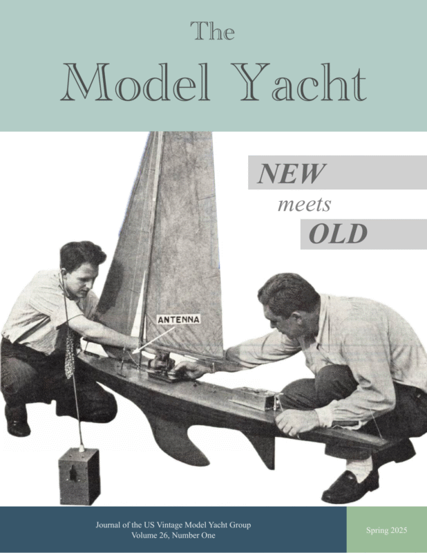
Spring 2025 The Model Yacht The Model Yacht is published three times per year by the US Vintage Model Yacht Group. Copyright 1989 to 2025 by the US VMYG. Reproduction for noncommercial purposes permitted; all other rights reserved. Other copyrights are maintained by the original holders, and such material is used here under the fair use provisions of the relevant copyright acts for nonprofit research and educational purposes. The Layline By John Stoudt Definition: A layline is a straight line (or bearing) extending from the next mark to indicate the course a boat should be able to sail on the one tack in order to pass to the windward side of the mark. (vsk.wikia.com/wiki/Layline) Editorial Address: John Stoudt 309 Sundance Drive Chester Springs, PA 19425 On the Cover: It’s 1948 and the big news is technology that can control your boat’s rudder! 77 years later tech is used in planning, in sailing, even in the positioning of marker buoys! See the stories on pp. 7, 14, and 16. Membership Renewals: Membership is now being managed on a rolling 12-month period. The annual membership fee will be due on the anniversary of your last payment. You will receive an email notification leading up to your due date. Please see the “Membership” page at https:// usvmyg.org/memberplans/ memberships/ for more information. Requesting a sail number: You can get a new sail number or transfer a registration from a previous owner here:https:// usvmyg.org/registration-2/ Select the class to open the correct form. There is a $7.00 fee for new registrations but no charge for transfers. The class coordinator will contact you to confirm your registration and sail number. The US VMYG is a 501(c)3 corporation. Finances As an organization, we are financially stable; however, our costs keep going up. In addition to your membership dues, we do generate some income from selling digital items from the website such as plans and literature. We are conservatively investing our assets in CDs. One area in particular that concerns the board is the costs of our journal. Printing and mailing costs continue to increase and were 60% of our total expenses in 2024. The last time we increased our membership dues was in 2014, and at that time Life Memberships were discontinued. At our current costs, a Life Membership covered the printing and mailing of the Journal for less than 2 years. All Life Memberships are at least 11 years old, and many over 20 years old. So current paying members are fully subsidizing all Life Members who receive printed journals. There are two things that Life Members can do to help balance the US VMYG membership income: • Switch to a digital membership • Make a yearly donation to help offset the costs associated with maintaining your membership. When you look at our bottom line, we are stable; however, our technology costs are rising, and new goals to digitize the history of our sport will require additional funds. About $10,000 of our assets are from donations to The Model Yachting Center. We are holding that to do the necessary research, while working on acquiring more donations. 1
The Model Yacht Inside The Leadership Team…….…..i The Layline…………….…….1 Inside………………….……..2 Spring 2025 Our Records The board maintains a cloud-based storage system for most of the materials we work with. We do not email a lot of documents around; we drop them in files and share the links with each other. That way we can review a document and make comments or editorial notes. We also use these cloudbased files to store all types of historical documents. We are passionate about maintaining the physical and digital archives. More and more of the hardcopy documents that we receive are being digitized and saved in the cloud. Over 800 items have been scanned to date. Strategic Planning Process…..4 Get Published North Central V36 and VM Regional Championships info..5 Silsbee………………..…..…11 Have you ever thought it would be neat to be published? Well, we can help with that! While we always have articles coming in, we ask each of you to think about something you might like to share with the model yachting world. You may be working on a boat, making a new rig for an existing boat, repairing something, making a fitting for a particular application, or building a jig to help you accomplish something on your model yacht project. Whatever it is, take notes and lots of photos. Work your notes into an outline and write a first draft. Send it to us (beck.jeff@gmail.com and jstoudt309@gmail.com) . We can assist you if you would like help. Do not be shy and give it a go. It is rewarding (both visually and in writing) to see your work documented in print. Drum Winch Option…..…….14 Regatta Rules Treasury and Membership Report……….…6 Geo-positioning Buoy Project………………………..7 Custom Cradle for Elizabeth Class Rule Change Request…15 Generating a Complex Ballast Pattern Using Technology…..16 Self-Righting Catamaran: Deck & Hatch Construction……….19 The Restoration of Sun-Kiss: A USA designed Marblehead….21 Notes on the Sliding Rig……27 Digital Legacy – Strategic Objectives…………………..30 It was necessary to update the regatta rules, adding a paragraph about regatta entries. The title of these rules has been changed to: US VMYG Guidelines for the Conduct and Management of Racing. The paragraph can be found at the end of the page at this link: https://usvmyg.org/us-vmygracing-rules/ Rule Changes Questions have arisen about the Vintage Marblehead class rules. As mentioned in the last issue of The Model Yacht, we take these questions seriously. The rules committee has worked through these questions and made some very subtle adjustments to the VM class rules. This work had us look at the V36 rules to ensure consistency, because the V36 rules grew out of the VM class rule. You may find the updated rules on the website: • https://usvmyg.org/classes/vintage-marblehead/vintage-marbleheadclass-rules/ • https://usvmyg.org/classes/vintage-36/vintage-36-class-rules/ 2
Spring 2025 The Model Yacht New Plans We have recently added number of plans to our website, including: Traditional VM Emma Duck, HB Tucker Festive, WJ Daniels Elusive, AW Littlejohn Plover, AW Littlejohn Foxtrot, Cecil Adams, featured in TMY V25N2 Restive, AW Littlejohn High Flyer VM Mentor, HE Richardson, modified Madcap Traditional V10R Skimmer, John Henderson, featured in TMY V25N3 Miscellaneous Items Rigging & Fittings for Marblehead Yachts, DA MacDonald Lassel Self-tacking Vane Gear, AR ‘Gus’ Lassel Braine & Vane Steering Open Positions Recently, we have lost two of our leadership team. Tom Alessi and Mike Denest passed away within one month of each other. They were both active R/C sailors and served the US VMYG leadership team in various capacities. “8 Bells” to both. We will see you at the great lake in the beyond. Ken Young (St. Charles, IL) and Tom Kiley (Rockport, ME) have picked up the Schooner and A Boat coordinator positions, respectively, and Stanton Smith (Annapolis, MD) has assumed the role of the Plans Coordinator. We have the following positions open: Archivist and the Australian, European, South Central, and South East Regional Coordinators. If you are interested in serving the US VMYG in one of these positions, please contact me for more information. National Regatta The National Championship Regatta will be held October 3–5, 2025 in Beachwood, NJ. It is being hosted by the Barnegat Bay Model Yacht Club. More details can be found here: https://usvmyg.org/wp-content/ uploads/2025/03/2025-NCR-NOR.pdf 3
Spring 2025 The Model Yacht The Strategic Planning Process Article by by John Stoudt It is easy for an organization’s leadership to get caught up in the day-to-day operation and not talk about the future and their responsibility to set the long-term direction for the organization. It is always easier to talk about yesterday rather than the future unknowns. There are many strategic planning models to define your goals and then work backward to define activities that will achieve those goals. A strategic plan starts with inspiration from your mission and vision statements and outlines what actions you are going to take to move the organization in the right direction. The Strategic Plan and Committee Guidelines can be found here: https:// usvmyg.org/about/strategic-goals-and-targeted-objectives/. This was done to develop 3- to 5-year measurable goals and actionable objectives. The US VMYG leadership team began the process of strategic thinking and looking forward as an organization. We (https://usvmyg.org/about/organizational-leadership/) approached the strategic planning process by . . . • Reviewing our organizing documents for guidance. • Address clarifying questions related to the Missions and Vision Statements. • Defining what the US VMYG should look like moving forward, – while respecting our 501(c)3 status, and – considering the pursuit of the Model Yacht Center The team circulated a survey that resulted in 20 suggested tasks. Example Sample chart for one identified item The summary of the goals, objectives, and actions is on the next page. 4
Spring 2025 The Model Yacht Strategic Goals 1. US VMYG will leave a digital legacy that supports our mission. 2. US VMYG has a growth target to increase membership by 15% (paying members) per year. 3. US VMYG will achieve a net annual income of $2,000 per year. Strategic Objectives 1. US VMYG will become the definitive, unique online source for model yachting history and information through a tiered approach to online articles, historical documents, photos, instructions, and videos. ○ Action items: digitize collection, Mystic Seaport Museum relationship, appoint contact, increase inventory, grow website traffic. 2. The US VMYG will assist individuals in all aspects of building model yachts through a collection of simplified articles written for beginners. ○ Action items: appoint committee, series outline, new beginner articles. 3. The US VMYG will encourage individuals to get started in model yachting by creating a beginner entry-level kit. ○ Action items: appoint committee, develop budget and logistics, reports to board, make kits available. 4. The US VMYG will encourage members and others to use a US VMYG online forum/community platform for ways to share information about vintage model yachting. ○ Action items: develop on-line forum, 50 participants, increase membership through forum. 5. The US VMYG will prepare articles for various non-model yachting publications to introduce model yachting to possible new participants. ○ Action items: write articles, submit to identified magazines. The board will be, with the help of others, developing the details and budget for these items. If you have an interest in assisting on any of these items, please get in touch with me. North Central V36 and VM Regional Championships, June 20-22 The Chicago R/C Model Yacht Club will host the North Central Regional Championship Regatta forVintage 36/600 (V36) and Vintage Marblehead (VM). The event will be June 20–22, 2025 at the nationally famous championship regatta site at Century Park, Vernon Hills, IL. The Notice of Race and Hotel and Regatta Site information are now available. Enter before June 1, 2025. Register online by completing the online Entry Form or by mail with the attached Entry form included in the NOR. 5
Spring 2025 The Model Yacht 2024 Treasury and Membership Report Report by Chuck Lage, US VMYG Treasurer Statement of Activity (Income Statement) Our statement of activity (Income Statement) for 2024 is shown below. It was a good year. Our revenue for products grew while donations were down. We finished with revenue down $1,300 compared with 2023. Our expenses were almost $2,000 lower in 2024, which left the US VMYG with a strong net income of $3,640. Statement of Financial Condition – As of December 31, 2024 (Balance Sheet) Our 2024 financial position indicates our total assets increased to $30,551 due to the addition of our net income while we remain free of any liabilities. Membership Report As indicated by our financial report, we had a good membership year. In 2024 we gained 36 new members while retaining 77% of our paying members. This gave us a total gain of 10 members while sadly losing one life member. 6
Spring 2025 The Model Yacht Article by by John Stoudt The Geo Positioning Buoy Project Holding station in heavy air. W Photo by Dave Baker The Geo-Positioning Buoy (GPB) is the result of the club’s effort to have a buoy that can be set from shore using a hand-held device to position it. The club’s two goals were: hy an article about some newfangled, hightech device in the US VMYG journal? Because this is a very cool development. Imagine being able to set up your club course without having to go out in your kayak or whatever boat you use. Well, now it is possible! You stand on the dock, place your buoys in the water, choose the course you want, and off they go. The buoys will stay on station until you tell them to come home (back to the dock), thanks to a computer control board installed in a special hull. 1. have buoys that we could place from shore, and 2. make our project available to other clubs. A team (Jim Freeze, Tim Good, Steve LaBrenz, and me) of club members was assembled to work on this project. The team and others searched the internet for reasonably priced automated buoys to no avail. We wanted geopositioning buoys. The on-board firmware communicates with your control device (cell phone or tablet) and numerous satellites while evaluating location and sending information to the two thrusters to keep the buoy on location. All very mind boggling. One of our club members found an expensive version. Another member found someone in England making 3D-printed buoys for his club. These buoys carry a weight out to the desired location and drop it. Robin Gray, the designer of these buoys, graciously sent us his CAD and 3D printing files. Our team redesigned the mechanism within the buoy (which The Chester Springs Model Yacht Club (CSMYC) wanted buoys that could be positioned without having to go out on the water to place them. 7
Spring 2025 The Model Yacht immediately reached out to the owner of the company (Baker Creations, LLC), David Baker. Our interest was in putting his electronics into our “hull”. We arranged to buy one of his kits and began the process of redesigning our Geo-Positioning Buoy. The team shared the photos of our design with Dave. A few weeks later we completed the redesign with the modifications necessary to fit his electronics into our hull. CSMYC is lucky to have a member who has access to a highend 3D printer. It is able to print the redesigned parts with speed, relatively speaking, and accuracy. We are printing the parts in PETG, which is a strong and UV-resistant plastic. Internal workings of the AnchorBot. Photo by John Stoudt we called AnchorBot) to allow it to carry and drop a 3.5-lb weight (anchor). Robin’s design carried a 2-lb weight. We knew we needed a heavier weight to keep our marks on station. It took us a few weeks to redesign the AnchorBot and get it working. Three days after we had successfully benchtested the AnchorBot, another club member found a more reasonably priced Drone Buoy using geopositioning. We We had difficulty getting the Geo-Positioning Buoy to function as we expected. The last test we made reminded us of a dog trying to figure out which tree to go to in the woods. The GPB, generally, went north when we told it to go north, but it would circle and move to the left, then move back to the right, and circle again as it moved in a somewhat northerly direction. We sent Dave a video of this behavior; we were constantly sharing our progress with him. He said, “send me your buoy, I know what is wrong”. So, off the GPB went to Colorado from Pennsylvania. Our hull shape required changes be made in the firmware. He had it one day, made the changes, and returned it to us. He made two adjustments, to accommodate the difference in hull shape, one to the forward thrust and one to the steering authority. Drone Buoy – https://www.youtube.com/watch? v=3hRrgBC0F9k&t=14s Geo-Positioning Bot – https://www.youtube.com/watch? v=8uo2tVCbr38 If you are interested in acquiring one or more of these buoys for your club information can be found here: • Baker Creations, LLC – https:// www.dronebuoyproducts.com/ • CSMY GPB – https://tinyurl.com/3sfw2jyj New electronics installed in a hull. Photo by John Stoudt These Geo-Positioning Buoys are available in several hull shapes and colors and must be assembled by the buyer. Complete instructions are available. 8
Spring 2025 The Model Yacht The Geo-Positioning Buoy is a 13-in diameter hockey-puck-shaped hull that is stable in 20-knot winds with its ballasted design. Before we realized how stable this buoy was, we developed a stability option in the form of a keel. A complete parts list is available for the GPB. The 3D-printed parts are available from a third party or may be printed by the local club. This buoy hull is printed from PETG for better outdoor durability, and it is rugged. It flies a large flag for visibility and has a bump rail (closed cell foam) that protects both the buoy and the boats from aggressive sailors. The thrusters are mounted on the hull. The design ensures that the buoys are watertight with specially designed seals. Tubular buoy holding station. Photo by Dave Baker All of these GPBs are controlled by an app on your phone (or tablet) using Bluetooth Low Energy (BLE). Pick the buoy you want to control, command its autopilot to move along desired headings, then touch the anchor button. You can also use stored waypoints and command the buoy(s) to them. Course rotations, translations, elongations and return-to-operator functions are available. BLE has greater connectivity range than standard Bluetooth with excellent performance over water. Any Bluetooth-equipped phone or tablet can control all of the buoys. There is also the option to plug in two servo cables from a radio control receiver for control over a much greater range (operational instructions are available). The Drone Buoy (available in various configurations) is a tube (original) that floats upright in the water and a new can-type hull. There is a short kit available from Baker Creations that provides the electronics and other parts needed to assemble in a tube (parts that you acquire locally). Drone Buoys are rugged and can handle all weather, wave, and immersion conditions with their highly stable designs. A circular-disk motor guard keeps keels from getting hooked and protects the motors. Choose either the 32-in length for radio control racing or the 48-in length for full-size applications. A new can buoy is now available. Thrusters installed on a hull. Photo by John Stoudt CSMYC has arranged for a company in New Hampshire to provide the 3D-printed parts for sale in various colors. They are a reasonably priced company, providing accurate, guaranteed parts and can be contacted directly. We can also provide the STL (3D printing) files if a club has 3D printing capabilities. We will also provide the printer requirements and print parameters. The hull shape, color, and flag make this buoy very visible from the shoreline. You can number the flags for course position and interchange the flags, as necessary. 9
Spring 2025 The Model Yacht The Anchored Buoy versus a Geo-Positioning Buoy These two buoys appear to behave differently, but this is not an accurate observation. They both react to the wind speed, current, and wind direction. The geopositioning buoy’s movement is more visible because the geopositioning software reacts quickly, making the buoy’s movement more noticeable. The anchored buoy, of course, is tethered to the bottom with a heavy weight (with a counterweight) that allows the buoy to move downwind as wind speed increases or to spin around the bottom weight as the wind direction changes. As the wind increases the anchor rode lengthens; as the wind subsidies the anchor rode shortens. The movement of the anchored buoy is subtle versus the GPB. But they both move about the same distance. This is true regardless of whether you use an anchored buoy or a geopositioning buoy. It is just more noticeable with the GeoPositioning Buoy because of the use of the thrusters guided by the software. Improved Firmware Dave from Baker Creations has improved the software now calling it Fleet Solution. This new program utilizes a main (hub) buoy and secondary (spoke) buoys. The spoke buoys can be up to 185 meters (600 feet) away from the hub buoy and still be controlled. The hub buoy can hold up to 40 waypoints. You set up the buoys (individually or as a group) with waypoints to define anchor points. They are set to the buoys to replicate the courses your club sails. Once the buoys are deployed to a particular course you have options if the wind conditions change. You can: • Shorten the course • Lengthen the course • Rotate the course clockwise or counterclockwise • Translate (slide) the course in any direction (including to another venue) • Send all the buoys to the operator’s location (come home command) You can also move an individual buoy, independent of the others. The buoys can also be controlled with a radio control TX/RX system. New Computer Control Board. Photo by John Stoudt 10 The GPB costs around $460.00 for the complete buoy depending on quantity purchased. This is a relatively inexpensive GPB.
Spring 2025 The Model Yacht A Custom Cradle for Elizabeth Silsbee Twenty five years ago Andrew Charters of South Carolina launched his beautiful schooner Elizabeth Silsbee for the first time. In January he launched her for the first time this year with all of the same equipment she had two and a half decades ago: transmitter, receiver, sails, bilge pump… He decided she needed a new launch/retrieval system to make the process easier for both the Silsbee and himself. Article and photos by Andrew Charters. Introduction by Ken Young. Elizabeth Silsbee under way. It’s been 25 years since I built the Elizabeth Silsbee. I sailed her a year or two ago, and everything worked well except for that trailer cradle. This is what I did to get her sailing again. Elizabeth Silsbee ready to launch. I had to build a new trailer to launch her with the keel bulb down. It’s too difficult to lower the fin keel after launching while trying not to get your feet wet. 11
Spring 2025 The Model Yacht I installed a hoist on a backyard tree to lift the schooner while I built the new cart. I took the opportunity to weigh two of my schooners for the first time. The Silsbee weighed 50 lb, and Bluenose weighed 70 lb. That is a big difference; I’ll weigh the rest of them later. The cart had to have a three-piece insert to hold the weight of the keel and bulb while traveling down the highway in the old horse trailer. Ten pounds of lead keeps the schooner cradle from floating during launching, which brings the weight of the cradle to 38 lb. It takes 28 in of water to float the old girl; that puts her about 8 ft from the shoreline. She’s guided with a 10-ft pole off of and on to the trailer. With a frisky wind, launch and retrieval can be tricky. I installed vertical guides on the trailer to help with that. The shape of the rails was taken from the plans. The finished cradle. Note the inserts to support the keel and bulb. Sunday, January 19th. Batteries are charged up. She sailed beautifully—no problems, other than the wind and the video. There was enough wind to get some speed up on both tacks, but poor performance with the phone camera couldn’t catch it. It launched and loaded on the trailer cradle very well. I use a broom handle to push the cart around for maneuvering. A 10ft by 1½-in pole guides the schooner in and out of the cradle. I push the cradle under the Elizabeth Silsbee loading into the horse trailer. schooner once the schooner is halfway in. My pole is also used to fill bird feeders; it has a 3-in deck screw on a 45-degree angle. It’s good for grabbing the schooner under the rail cap. This is not for delicate little schooners built mostly for display. Things get rough when it’s windy. 12
Spring 2025 The Model Yacht The trailer rails that hold the schooner are 24 in long and are cut to the shape of the hull. I copied the lines off of the plans to get the rails centered in the displacement lengthwise, keeping them parallel with the centerline. I used 1½-in square vertical uprights to attach them to a ¾-in treated plywood base 34 in long by 12½ in wide. I used 7-in plastic wheels in the back and 6-in wheels in front for ride height, with three inserts to support the keel and bulb while travelling down the bumpy highway. A bungee cord holds the schooner in place. Waiting on the weather for her second sail. The cradle. Note the shaped rails. Elizabeth Silsbee on the cradle and cart. Note the fin and bulb installed. 13
Spring 2025 The Model Yacht Drum Winch ption Article by John Stoudt T om Alessi, an R/C sailing enthusiast, club member, and friend passed away recently after battling cancer for a year. One of his last wishes was that we finish the schooner Atlantis he had been building. So, I had the opportunity to work on this boat for him and discovered that Tom had an ingenious adaptation for a drum winch to adjust the sails. And we know how hard it is to find a good drum winch that works well. GoGilda servo on stand. The servo used is a GoBilda servo from ServoCity, a 2000 Series Dual Mode Servo (25-2, Torque; https:// www.servocity.com/2000-series-dualmode-servo-25-2/). This is a high torque (350 oz-in at 7.4 V), dual mode servo. Dual mode means it can rotate 300 degrees (adjustable) or be in continuous rotation. Atlantis, completed as Tom had hoped. 14
Spring 2025 The Model Yacht Another accessory is the Servo Travel Tuner (https:// www.servocity.com/ servo-travel-tuner/). Servo tuner. Yet another really cool item available from ServoCity is the servo stand, which is built for a standard size servo: 1804 Series Servo Stand (https://www.servocity.com/vertical-aluminumservo-mount/). Servo Programmer With a simple device from ServoCity you can change the modes from one rotation option to the other, using a 3102 Series Dual Mode Servo Programmer (https://www.servocity.com/3102series-dual-mode-servo-programmer-1-1/). There are also two drum options available, the most optimal for our application is the 3410 Series ServoMount Winch Pulley (25T Spline, Dual Spool, 112 mm circumference; https://www.servocity.com/ 3410-series-servo-mount-winch-pulley-25t-splinedual-spool-112mm-circumference/ Drum, servo, and stand. Drum winch servo comparisons. Class Rule Change Requests We’ve created a Class Change Request Form (https://usvmyg.org/classes/rule-change-request-form/) to collect change requests or comments on any of the US VMYG class rules. The Rules Committee will review your request and may contact you by email with any questions or clarifications. Please understand that changes to class rules take time and require consideration of the needs of all members of the class. Be specific about the exact rule that you want to change and provide your proposed wording for the rule and evidence you have to support your proposal. You may upload images to support your request. 15
Spring 2025 The Model Yacht Article and images by Steve LaBrenz and John Stoudt Generating a Complex Ballast Pattern Using Technology Ballast details from Tritonia II plan. The Setup (John’s Story) Fifteen minutes later Steve asks, “How is this?” He had found an app for his smartphone that enabled him to take multiple photos of the part and generate a 3D rendering in the application. It could display the part in a couple of different ways including three dimensions that could be rotated and a wire frame image with many points and the connecting lines. One of my (John’s) students in the Model Yacht Restoration class at WoodenBoat School needed a ballast for the Marblehead class boat she was building. I contacted the individual who often casts ballasts for model yacht builders. He asked if I could send him the plan information for the ballast. I did. His reaction was he would have trouble carving both the halves of the pattern and get them identical. So, what do I do? I rooted around in my collection of patterns. Scanning, Editing, and Printing (Steve’s Story) Scanning technology has been in use for a short period of time but has only recently advanced so you can use a series of pictures from your phone. Objects can be digitally constructed and preserved as a computer file. Polycam is a smartphone app that has a supporting website. You can take a series of pictures and upload them to the Polycam server to be reconstructed into a digital object. We constructed a digital, 3D structure of the complex Marblehead ballast from Tritonia II using about 30 pictures (not many actually), and were then able to download a file for 3D printing: an STL file. Starboard side pattern. I found the half pattern I had carved a few years ago for this boat. It goes without saying that I had forgotten I had done this. I was thinking about alternate ways to complete the other half of the pattern and cast the ballast. While in my shop one day with two other club members working on a project for our club, I asked Steve if there is a way we could digitize this shape, make a mirror image, and 3D print the two halves? I turned back to our work at hand with Jim Freeze and forgot about the question. There are some caveats about using Polycam. Unrestricted use of the app costs $150.00/year. If you don’t want to pay, you need to perform some tasks to be able to use more pictures for the project, like watching an advertising video. So, you need to partner with a group to share the cost and get a lot done in a month or a year. 16
Spring 2025 The Model Yacht The wooden, carved half-ballast was lying on a cleared work surface; all materials had been moved away from pattern. Following the directions in the app, I took about 30 pictures of the ballast, 10 each across the top, left side, and right side. The pictures were taken directly in the app, not using the phone’s camera app. I selected the option to indicate that I had finished taking pictures, and the image files were uploaded to the Polycam server for processing. In about 5 minutes, the digital re-construction of the half-ballast was done. Polycam selection menu. Processed image. Note the flashing. Post-Processing Unfortunately, a free-to-use account with Polycam does not provide the best or most useful features for exporting the completed structure. You are limited to the GLTF (*.glb) file format, which needs to be converted into an STL file for 3D printing. Fortunately, I have experience in CAD and file manipulation, but being able to export an STL file directly from Polycam would have simplified the process. I used FreeCAD to import the GLTF file, then using the “Part Workbench” in FreeCAD, performed a “Convert to Solid” command and exported the resulting solid as a STL file for 3D printing. There’s a lot of extra material around the ballast associated with the structure in the file and the actual scale of the object needs to be set. Some of this extra material was removed (digitally) before proceeding to 3D printing, providing the final shape to print as shown here with additional nonmaterial removed, holes added for alignment of the two halves, and threaded rod installation. Showing extra material removed (flashing). The material removal can be performed in a CAD program or using the online Tinkercad website (www.tinkercad.com). 17
Spring 2025 The Model Yacht I was also able to scale the structure in Tinkercad so that the part was the correct dimensions. On the original piece, there were pencil lines which showed up in the digital structure as indents on the surface. I was able to ensure that the indents were 2½ in apart, which scaled the structure correctly. Final images of part in CADD. 3D Printing (John’s Story contd.) The following settings were used to 3D print the two ballast halves: Assembled mold. The small amount of misalignment was sanded off. It did not matter that the screw heads stuck out from the one half of the mold. They were easily filed off during part cleanup after the casting was poured and cooled. • Printer: TronXY S5A, 300⨉300 print bed • Filament: PLA, (210/60) but I recommend using PETG (230/65) • Nozzle: 0.4 mm • Layer height: 0.2 mm • Infill: 15% • Top/bottom layers: 4 • Support: On, Everywhere This process works and is a good way to get your pattern ready for mold making and casting. It provides accurate 3D printed halves of your carved half of the pattern, regardless of the detail. The 3D-printed pattern halves arrived from Steve. They were a little rough and needed to be cleaned up. The residual flashing was removed. The outside faces were sanded lightly with 80-grit sandpaper, filled with Bondo, and sanded a second time with 120-grit sandpaper. This filling and sanding was done twice to get an acceptable outer surface finish. Finally, the halves were sealed. I glued dowels into one half of the mold and drilled out the alignment holes in the other half slightly so that the pins would go in easily when assembling the halves. I checked the two halves for alignment and fit. There was some warpage so I used round head wood screws (1 in, #8) to hold the two halves together tightly. Clearance holes were drilled in one half and pilot holes in the other. The screws were inserted and screwed tight, pulling the halves into alignment. Carved pattern, printed pattern, assembled pattern. 18
Spring 2025 The Model Yacht Self-Righting Catamaran: Deck and Hatch Construction This is a follow up to the article “Pop-Up Manufacturing,Self-Righting Catamaran”, published in Volume 25, Issue 3 of The Model Yacht. Article and photos by John Stoudt The boat has one-piece plywood decks with custom-planked hatch covers. The hatch cover shape was dictated to some degree by where the self-righting sheet would exit each hull on the deck. Each hatch cover had reinforcing pieces on the underside to provide strength and shape. This boat did not require planked decks. So, plywood was a good option. There is a supplier in California, Cherokee Wood Products (https:// www.cherokeewood.com/) who sells ⅛-in Baltic Birch plywood in 60- by 60-in sheets. They will cut this down for you to any number of size configurations. They cut the 60⨉60-panel into five 12- by 60-in pieces for my purposes. This plywood is rated B/BB face quality. Both faces have no blemishes, with the B face being the better quality. With two coats of epoxy applied and sanded correctly, the outcome is a beautifully finished deck. Underside of hatch cover showing reinforcing pieces. The deck blanks were cut slightly oversized. The shape of the hatch openings was designed to mirror each other with an offset curve toward the bow to accommodate the fairlead exit location for the self-righting lines. The fairleads are on the inside edge of each hull. Hatch cover diagram. 19
Spring 2025 The Model Yacht The hatch covers were glued up with 5/32- by ½-in cedar and pine planking and were built oversized so they could be cut to the final size later. The hatch cover edges were made from ⅛- by ½-in aviation Baltic Birch plywood glued up right on the hatch cowlings using wax paper and masking tape to protect the decks and the cowlings. When the glue was set, the tops were sanded even so they were 1/16 in higher than the cowlings. I left the hatch edges on the openings and glued the tops onto the edges in place. When the glue was set, I removed the hatch cover assemblies and trimmed the covers to a ⅛-in overhang all around. Hatch openings with the coamings in place. I made a cardboard template for the shape of the hatch opening and reduced it on all sides by ⅛ in. The decks were taped where the cuts were to be made, and the pattern was traced onto the decks, remembering to flip the pattern. I cut the openings with a jigsaw, and glued the decks in place onto each hull with thickened epoxy. I filed/sanded the openings to the final shape. There was enough surface area to glue the hatch cowling to the edge of the openings. Using ¾-in wide pieces of 3/32in aviation grade plywood, I cut the pieces to length and glued them into place using TiteBond II. When the glue was set, I sanded the top edges so they were even. The deck and the hatch cowlings were coated with epoxy; I made sure that the corners between the decks and the cowlings had a liberal amount of epoxy brushed into the corners to form fillets. This helps ensure that the seams are watertight. Completed deck and hatch cover. 20
Spring 2025 The Model Yacht The Restoration of Sun-Kiss: A Marblehead designed in the USA A.R. Lassel’s Sun-Kiss dominated the races of the 1940s in the US. She was an example of what could be called the “third generation” of M boats. All pretense of “yacht-like” lines is gone, and the waterline length is carried as far as the rules will allow. Here is her designer’s description, which accompanied the publication of her plans in Model Yachting Monthly in September of 1945: Article and photos by Graham Reeves The Sun-Kiss design shown in the MYM supplement stems from Faithful and Gurgles, The 1937 and the 1941 National M-Class champions, and from Roschana, runner-up in 1937. Ted Thorsen re-drew the lines of these yachts to conform to those of warships having a speed that produces the constant 1 in the speed–length formula. Hence, an M-Class yacht should make 2.04 naut. miles per hour when a 500-foot warship makes 22.5. She is not giving away any potentialities due to waterline length, has powerful sections and flat chine line. Her lateral plane is more than adequate, so that, if wetted area be considered more important than dynamic balance, the width of the skeg may be reduced. On the Sunmaid, the last year’s National Champion, the skeg is a mere strut. The keels of Paul Collet’s Sunmaid and How’d Curry’s Sunapee weigh 13 lb, and J. McKinney’s Vagabond and Dr. Peal’s models from this design weigh 13.5. The design of the keel is the result of an observed phenomenon in towing 50-inch models of different keel designs at about twice the normal speed. When the junction of the keel with the hull was rather thick, and the yacht towed with a decided heel, the resistance as compared with that of the upright position, shot up eight-fold. The only visual 21
Spring 2025 The Model Yacht Sun-Kiss profile and water lines. difference was a short but steep secondary wave in the way of the keel. The obligation, then became the elimination of this secondary wave; the seal-flipper keel as shown on Sun-Kiss represents an effort in that direction. The scope of the sliding rig is sufficient within the range of 0 to 18 mile winds. Sun-Kiss was a West Coast boat that was raced on artificial ponds that were deep and generally right on the shore where the wind blew straight, hard, and often. Back in Marblehead, MA, the boats raced on historic Redd’s Pond: a natural venue of great beauty, the occasional submerged rock, and notoriously fickle winds. J. Selmer-Larson’s Broom V, a contemporary of Sun-Kiss, shows how this difference in environment affected the design. Note the shallower draft and hull shape tailored to lighter airs than those of California and Washington State boats. Broom V lines for comparison 22 Sun-Kiss body plan.
Spring 2025 The Model Yacht The Sun-Kiss to be restored. Sun-Kiss was designed in the US around 1945. It was published about 1952/3 in the UK’s Model Maker magazine under the number MM268. Only three were known to be built in the UK. The first was called Fandango. It was registered in 1952 with number K 558, built by J Weeks of the Bristol MYC, and raced in the 1952 M Nationals at Birmingham with a standard rig and in 1953 at Hove with the sliding rig to the published design. The second was believed to be Samantha, again from the Bristol MYC. The third was called Sun-Kiss, built by Mr J Willoughby of the Leeds & Bradford and Fleetwood Clubs, Number K1028, in 1957. This and Fandango were the only ones ever registered. The last one built by my old pal John Gale after 1990 and now owned by VMYG member Anthony Warren. The Sun-Kiss deck with sliding rig. The start of the strip down The solid lead fin was removed (with difficulty after 70 years), and the deck was removed. The deck will be replaced with a lighter plywood deck. Unfortunately it wasn’t possible to save the mahogany deck rails because they were too fragile. I cut teeth in the end of a piece of ¼-in diameter (3/16-in bore) brass tube and used it as a drill to drill down over the keel bolts to free the lead. When I refitted the lead, I sleeved the holes with the brass tube I used as a drill. 23
Spring 2025 The Model Yacht These photographs show the extent of the split joints between the planks. In most cases the cause of the splits is a combination of bad storage and the type of glue used. The glue used at the time was either Casco or Cascamite. In World War II Casco, a casein glue, was used for glueing wooden airplanes together. After Cascamite came Aerolite 306, a twopart urea-formaldehyde/ acid-hardener adhesive that was used by full size as well as model boat builders. The hull stripped ready for sanding and painting The weight of the bare hull was 2 lb 12 oz. The solid lead fin weighed in at 13 lb 4 oz. The original deck, which was 5/32 in thick, weighed a hefty 1 lb 7 ozs. It was made out of pieces of wood glued together. This makes me more certain that she was built in the early 1950s. The brown patches on the bare hull are from burning the paint off, which I prefer over using a chemical paint stripper. The sheathing inside the hull added another 6 oz, for making a total weight of the restored hull 3 lb 3 oz, including the rudder (1 oz). Although I sheathed this hull on the inside between the ribs, I now prefer to sheathe the hull on the outside prior to painting. The new deck weighed in at 10 oz unpainted, a savings of 13 oz. The Sun-Kiss hull ready for sanding. 24
Spring 2025 The Model Yacht Doris H was one of the first commercially available fiberglass marblehead hulls available in the UK. She had a flipper-type fin similar to Sun-Kiss. Doris H was designed by W H (Bill) Daniels and won the UK National Championship in 1951 and 1954, which may be attributable to the lack of Sun-Kiss boats built in the UK. The Doris H drawing includes the table of weights below. Hull: 3 lb 8 oz, including deadwood and skeg Paint: 12 oz Deck: 14 oz Vane: 4 oz Deck fittings: 6 oz Lead fin: 12 lbs 8 oz Rig: 1 lb 2 oz Total weight: 19 lb 4 oz The fin from the Doris H. A Doris H hull bought from Roberts of Hove. Finishing the Rebuild The original deck was set inside the inwale. I decided to remove the upstand and set the deck on top and glue it onto the inwale. This was a better option because the glue used on the inwale was suspect due to its age. I wanted to maintain the strength in the hull because this was to be a sailing model and not just for display. I also screwed through the hull into the inwale every 4 inches for extra strength. The deck I used was 1/8 in thick rather than my usual 1/16 in; it was fitted using aliphatic resin adhesive, and pinned. 25
Spring 2025 The Model Yacht When I started to fit the rudder I found there was something amiss. I realized early on that the rudderpost was vertical and not set at an angle as per the drawing. If I was building the boat, I would have carried out the same modification in order to make the vane gear easier The rudder was flipped to account for the straightened rudderpost. to set up. What I didn’t slide was screwed in a fixed position as I decided realize at the time was that the rudder needed to be not to try and control the sliding mechanism by radio. turned upside down to make it more in keeping with accepted trends of the time. The photographs and the drawing make it all clear. You will note that I kept the Below are photographs of the finished boat ready same rudder for originality. for the water. The boat is not only set up for radio but can also be free/vane sailed with some additional The rig I used consisted of the original sliding rig that lines added to the booms for sail adjustment, the was on the boat. The mast and booms were reused servo link removed from the rudder, and, of course, from another boat of the era, and a brand new suit of not forgetting to fit the vane. The original slotted varnished terylene sails. Varnished terylene was the tiller arm was reused along with a new vane pintle new model yacht sail material of the 1950s. The mast holder. The refinished Sun-Kiss deck showing the sliding rig. The Sun-Kiss afterdeck. Note the rudder servo. 26 Sun-Kiss ready to sail again.
Spring 2025 The Model Yacht Notes on the Sliding Rig This article is republished from Model Yachting Monthly, Volume 1, Number 7, September 1945 Article by A.R. Lassel A make them sail properly”. review of events and ideology that led to the prohibition of the sliding-rig on the Xclass is timely. [ED. NOTE: The sliding rig is now permitted on the X-class.] So is also a speculation on the function of this device, and the benefits derived. At the receiving end of the criticism the sliding rig is linked up with the vane steering gear. Together they have to sustain the barrage, of which the following is a representative sample—“There is a group of skippers like myself who do not approve of the appearance of a vane stuck on the stern of a yacht. Also we feel that yachts should not be so poorly designed that it is necessary to move the mast six or seven inches to In order to acquaint the reader of the habitude of the opposition to those gears that are now supplanting the earlier Braine gear, another quotation is pertinent— “When the X-class was first introduced, we were told that here was a class of yachts that would have to be designed correctly and no gadgets such as a vane would be allowed. Also that the sliding rig would be prohibited. A number of Evidently a few skippers found their Xboats were not so hot, unless a vane was used to steer them, and so vanes were then allowed”. And, referring to a writer on the subject of 27
Spring 2025 The Model Yacht field for the legal talent of the pond to practice on. dynamic balance, the spokesman continues—“He writes at great length on “dynamic balance” as if that would be the objective of all yacht design, and that appearance and similarity to a large yacht should be secondary. As a matter of fact, I do not agree with his theories of what he calls “dynamic balance”, and I think his use of the term is not entirely correct. I prefer to just call it “balance” and think that a great many factors enter into designing a yacht other than moving the underwater appendage aft”. But the prospectus goes the whole hog and unequivocally for “balance”. The “most perfectly balanced hull” is the unconditional aim. One man wrote that from the windows of his residence he would look over the yachts moored ln the harbor, and look as he may he never saw one with a vane steering gear. Since he was defending the appropriateness of the Braine gear, the inference is that he could see all kinds of boats equipped with the Braine gear. This specified balance should have been qualified by the adverb “metacentrically”, for this thus expressed aim was that of the dark ages following Admiral Turners analysis of curve of areas of a hull upright and heeled. He had only shown. how static balance could be achieved. Whoever ascribed a dynamic attribute to metacentric analysis perpetrated a mischief, for afterward we find a lusty crew, headed by a now defunct model yachting magazine, ramming the nostrum down the throats of model yachtsmen. In order to evaluate the statement quoted earlier, it may be said that few contemporary designers dare not to conform to the precepts of metacentric balance. Why the model yachting world did not demand an empirical test of this ideology and accepted only some sort of ontological proof based on emotional reactions solely, is an indictment. As to quality of verisimilitude on the part of the sliding rig, it may be said that the Square-meters classes, of which the X is an ectype, have a close approximation of this device below deck. ln order to clarify the principal factor in the search for balance, that balance which makes the boat go where you want it to go, the following speculation is made. If we look beyond the impressions of the uninitiated, we find that the sliding rig is just another means of achieving the same ends as the two centerboards on the Enterprise and the Ranger, officially purporting to ease the steering, but mechanically, to change the relation of the lateral plane to the effort. Therefore, one may deduce that it is yachty to do that, but our rules do not countenance the centerboards, so the alternative is to move the mast. A square-ended barge is a metacentroid, more perfectly balanced than anything labelled perfect before. The in-wedges check with the out-wedges whatever the heel is, and sure enough. whatever the trim is. If she be trimmed level fore and aft, the center of the lateral plane is on the same line on the profile as that of the buoyancy and gravity. If we, after acclaiming the perfection of the design, try to tow the barge from the conventional bridle we find, should the barge be trimmed by the head, she takes charge of the steering, for the lateral plane having been moved forward is in an unstable position in relation to the longitudinal resistance. She is seeking a position of stability, and not finding it, in the meanwhile ranging at all angles abaft the tow-boat. Before proceeding, we might as well consider the yacht-like quality of the Braine gear and even label it “gadget” in a derogatory sense. The prospectus heralding the advent of the Xclass did not specify yachty appearance. This item, generally, attaches itself to the rules afterward; it is never defined, thus leaving a wide 28
Spring 2025 The Model Yacht Should she be trimmed level, the steering qualities are improved, yet not good enough for a discerning tow boat skipper to go into raptures. to change the center of effort. The result is that we often see a yacht choked to death as it were, by the jib being hauled amidships, still luffing with the mainsail alive. The aspect is not very impressive, for such trim is a sure way to convert propulsive force to induced drag. But, should she be trimmed by the stern, with the lateral plane moved aft, she becomes as tractable as Mary’s ovine companion, and gives the skipper confidence in bucking a strong ebb tide. As a ship that steers well sails well, so a barge that steers well tows economically and safely. The other method, call it “sliding rig sailing”, recognizes the fact that the best sailing position of the mast CHANGES with the strength of the wind. In other words, that no such thing as perfect balance exists, that the trim of the sheets can not be compromised for the sake of tipping the center of effort one way or another, and that the center of effort must be moved to suit the reactions on the hull and thus complement the steering device. In all these situations she was equally “hot” as pertains to metacentric speculation, yet that fact gave no assurance whatsoever how would be the steering, but when the lateral plane had moved aft, she became dynamically balanced to a moderate degree. Had the sides of the vessel been curvilinear instead of straight, the experience would have been duplicated. Although model yacht designers pay tribute to the ideology of dynamic balance by designing the lead bulb as a compromise between efficiency as agent for stability and the need of a recessive leading edge as a factor in dynamic balance, they do not analyze or evaluate their compromises, they just follow the custom and often denounce nonconformity. They are happy with the small favor received by way of balance that really counts. Some day they will be asking for more. The coordination of the human mind and the hand is superior to any steering gear yet invented, but a vane working with a quickly operated means of adjusting the center of effort fulfills all requirements of an automaton, doing the job remarkably well, never falling asleep or having its attention diverted. A skipper of a yacht so equipped does not fear to enter a race on a strange pond without an elaborate tuning-up process. One leg of a tack is enough to check his prediction of mastposition and a split second to correct it. The skippers that are accustomed to use the sliding rig resent the imposition that forces them to muddle up the trim of the sails for the sake of steering; no such frustration is present in the prototype, so why should the model suffer? For some of us, toy boat sailing lacks enticement, it does not seem rational for intellectual satisfaction. There are two ways of sailing a model close to the wind. One method may be called the “toy boat method”, due to the identical handicaps confronting the skipper of a toy boat and that of a model with fixed mast position, or where the movement of a mast is constrained by rules. The product of the toy-maker has a rather ineffective steering device, the Braine gear on a model has no automatic lee helm and, no rational solution for the defect, while the vane is functioning acceptably only with the mast in the “best sailing position”. Due to these deficiencies the only recourse is to compromise the correct trim of the sails in order If some of us consider, factually and realistically, the hoax that led to the erection of that shrine to the golden calf, the proscription of the sliding rig, we shall have a wider cleavage of attitudes, and if these be brought up to a rational level, we may arrive at reasonable conclusions. This article is for that end. 29
Winter/Spring 2025 The Model Yacht Digital Legacy – Strategic Objective Article and photos by Chuck Lage and the US VMYG archives A-CLASS YACHTS IN A RACE T0 WINDWARD Left to right: “Westward IX,” “Minerva,” “Redskin” MRS. W. G. BITHELL STARTS “MINERVA,” A-CLASS Note Braine Gear, fittings and rigging A • Donate your papers, magazines, books or other paper items related to model yachting. (Please reach out with a list so we can compare it to what we already have in our archives) We will provide you with a taxdeductible receipt. • Or, loan items to us for scanning if you prefer not to donate. We have already done this twice and mailed the items quickly back to their owners. • Donate funds to US VMYG to support our mission along with this project. s you have read by now, the Board worked with the leadership team to establish five strategic objectives to drive our activity over the next few years. Over the past few years, several individuals have donated their collections of books, magazines, journals, pictures, newsletters, articles, videos, postcards and other historical records on model yachting to us. This collection fills 13 banker’s boxes and includes over 1,700 unique documents. Although fun to poke through, we kept thinking, nobody else will ever see these items. So, we hatched a simple idea: let’s digitize as much as possible and post them on our website for others to enjoy and be able to search for specific topics. Input / Output With a little internet digging, we discovered there are many databases, museums and other sources to find input for this project. Most importantly, we realize we also need an easy and engaging way to display and share this information. Soon we will start looking at plug-in modules to our website to manage and make this information available later this year. Organizations come and go, but once digitized, we will look for a way to endow our Digital Legacy to be enjoyed by future generations. I wondered: will this take 5 years or 5 months? So, I started scanning using a home printer/copier/scanner. Over about 3 months I scanned over 800 items into searchable PDF files. Soon we will begin to share this treasure trove of information. How Can You Help? • Join the research effort to conduct internet searches. Contact Chuck Lage at usvmygt@gmail.com • Join the project committee or share your thoughts and ideas, again contact Chuck Lage at the above email. Thank you for your continued support of the US VMYG and hope you enjoy browsing and reading from the Digital Legacy in the very near future. 30


