- Title. Author. Summary
- Title. Author. Summary
- Title. Author. Summary
- Title. Author. Summary
- Title. Author. Summary

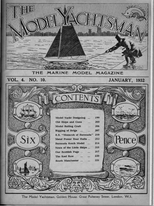
SALE N\\\ RE) \ ; i i Wy i Model Yacht Designing … 199 Old Ships and Guns vod 203 Model Sailing Craft Rigging of Brigs … ke 206 = 207 S.S. ‘*Monarch of Bermuda’’ 210 Metal Power Boat Hulls … 212 Bermuda Ketch Model News of the Little Ships … 215 Our Scottish Page … The Keel Row South Manchester … fina The Model Yachtsman, Golden House, Great Pulteney Street, London, W.1,
January 19382 The Model i Yachtsman. ei éi im SAILS Pts, Finest Union Siik and of Bobbin, etc. :: BodeRepair en Service. naar Sail Cloth. Spars, Sails, Fittings and Accessories . for all Classes. Bunting Flags and Pennants any size and design. Chas. Sadia, To order only. Decorative, Water-Line & old-time Ship Models Drown, Built and Restored. 8, Ullswater Rd., Since West Norwood, 10, Celbridge Mews, Porchester Road, S.E.27. LONDON, W.2 “i y, WHAT WORLD % USERS aa SAY OF “RYLARD,”’ Regd. The Best Marine Varnish ‘‘We confirm the good results and our satisfaction with your ‘‘We have used ‘RYLARD,’ our Motor Boats, ‘RYLARD’ Varnish for too highly of the results obtained.”’ Hydroplanes pies Mads ons and Propellers.’’—Soc. An Navigazione “I Enamel a number of years and cannot speak which for three years we have used on and rary Aerea, Genoa, Italy. have used your ‘RYLARD’ Varnish ‘**RYLARD’ ‘ ; Varnish , has met all our for six years and am quite satisfied.”’ requirements as a marine varnish.”’ P. S. Arnott, Sydney, Austrailia. Keith Boat & Engine Co., Chicago. Ideal for Sole LLEWELLYN all Model Craft Manufacturers: RYLAND, LTD., Branches over all the Birmingham, England World. In replying to Advertisers, please mention THE MODEL YACHTSMAN.
THE Vol. 4. MARINE MODEL MAGAZINE. JANUARY, 1932. No. 10. MODEL YACHT DESIGNING FOR’ BEGINNERS. By ‘“ YARDSTICK.” Illustrated with Diagrams by A. W. Littlejohn. Part IV. OW it» has been mentioned that a vessel displaces a body of water equal in weight to her own weight. The centre of buoyancy is the centre of gravity of the displaced volume of water, and unless other influences of a more powerful nature are at work, the centre of gravity of the vessel will place itself directly under the C.B. Now when the wind presses on a vessel’s sails it heels her and this tendency of the C.G. to return to its position vertically under the C.B. provides the righting impulse. Thus we have two forces at war—the wind trying to heel the vessel, and the power of gravity trying to keep her upright. If this is considered as a sort of see-saw, then the C.B. is the point about which the see-saw pivots. Another way of looking at the same thing is to consider that the vessel rests on a ledge of water, externally, and the two forces struggle to heel her or right her over this shelf. This is known as the metacentric shelf. Now obviously if, by reason of the fore and aft sections being out of harmony, the shelf slews to one side or the other of the vessel’s proper course, a steering effect is at once introduced. In other words, the tore-and-aft longitudinal axis of the vessel must remain in the same plane parallel to her course and the surface of the water, however much she heels. Now if, for example, we take out a big piece of the hull forward when she heels and only put in a little bit, we obviously decrease the displacement forward. What we, therefore, have to do is to see that the in-wedge and the out-wedge are so balanced that they do not alter the fore-andaft position of the E.G. Now obviously if these have no effect on the canoe body without keel, they will likewise have no effect on the hull complete with keel; so, having drawn the canoe body, we may as well prove it before adding the keel. The way to do this is to strike a heeled waterline across the boat. Although the vessel would actually rise if this were done, for calculation purposes the heeled waterline is taken through the intersection of the |.w.l. and the centre-line, and it will be sufficient if the vessel is considered at her maximum angle of heel—namely, just before her gunwale is awash. Strike this across the section plan as shown in Fig. 10. The underwater areas of each section are then calculated first on an even keel and then heeled and tabulated. It is possible to do this mathematically by Simpson’s rule or the Trapezoidal rule, but as our drawing has been done on squared paper we will simply count the squares. Each square represents a square inch, and each small square one-
uedAqGAvNpoSy*‘oYl,,UdIaeqTsfyg}sUturf?)pgjtnbrvo‘uijan1)y”,sreNYwigQSUTIMOo}9a8 200 – The Model Yachtsman January 1932 — —_| \ \ \ )
OU,PoTeIemys10B‘VOMTSuly],ourfrAp7g“Y}4tXdi8laLds“xjNEGfYRO}Msoeyuq‘prdi January 1932 The Model Yachtsman. 201
202 the balancing points (which are their C.B.) come in the same fore-and-aft position. If there is any discrepancy, it must be corrected. If, for instance, the heeled curve has its C.B. farther forward than the upright one, and examination of the lines shows that she looks a little lean forward and full aft above water, this must be rectified by filling out the topsides forward and lightening aft in the latter case possibly pinching the transom in. These curves are shown in Figs. 11 and 12. Whilst we are dealing with the curve of areas of the canoe body, we may as well see what displacement we have got so far without keel. As the base line of the figure represents the length, and the lines erected on it representing the sectional areas are square measure, by simply counting the squares in the figure we get the cubic displacement of the boat. This is 597-798cu. ins. It will be noticed that up to this point the hull has been designed without the use of a single calculation; but now to apologise to my readers that I must really As the boat under Figure 11. design js an A-class Now it is not the intention of these articles to quote or explain the A-class rule, as anyone can read and understand this for himself. The Q.B. length allowed, without penalty on 49.7 ins. M.W.L., is 47.22ins., and half the excess is .49 ins., which is added to the L.W.L. and gives us an L measurement of 50.19 ins. After these adjustments have been made, we can proceed to put in the keel. The first question to determine is whether we are going to make her full-keel or fin-and-skeg. Now, provided the hull is right and the keel is put on right, there is not a great deal of advantage whether a full-keel or fin-and-skeg is used; but the former is more difficult to design properly—in the writer’s opinion, at all events—and the novice for his first essays will be well advised to try the fin-and-skeg. Afterwards, as he gains knowledge, he can try the fullkeel and form his own opinion as to their relative merits. (T’o be continued). tC Curve of Areas showing (.B. of Canoe Body on an even keel | Figure 12. in which quarter beam measurement figures, the buttocks have been arranged so that the second buttock falls on the quarter beam. The waterline beam is 14.1 ins., so on the sheer plan we strike a waterline one-tenth of the beam (i.e., 1.41 ins.) above the waterline at each end of the boat, and mark the spot where it intersects the Q.B. buttock. The distance between these spots, measured in a fore-and-aft direction, is 48.2 ins. Qteae In order to get the weight of the boat it is necessary to divide the number of cubic inches of displacement by 27 for saltwater or 27.7 for fresh water. As we are designing an A-class boat, which is measured in salt water, we accordingly divide by 27, which gives us a weight of 434]bs. score. aos have January 1932 for the canoe body. Now the kee] appendage will displace about 7} lbs. for a boat of this class, so that our total weight will come out at about 50 lbs. As the desired weight is approximately this, it will not be necessary to make any alteration on this 36ST I introduce them to the only sum that is unavoidable in the designing of the hull. we | Model Yachtsman. hundredth inch. It will be recalled that we advised the use of paper squared to inches and tenths of an inch. Next plot the areas so found on a base line on a convenient scale. The L.W.L., of course, forms the base for these diagrams. Having set out these measurements, complete the figures by drawing a curve through the points at the end of each section area. Balance these curves on a pin-point after cutting them out of cartridge paper and see that 1 oer i The Curve of Areas showing C.B. of Canoe Body heeled to an angle of 25 degrees.
January 1982 The OLD Model SHIPS Yachtsman. AND 203 GUNS. By Joun ALDEN. Reprinted from The Boston Sunday Globe. Collections of Ship Models are not common, but we think Mr. William E. Meyer must be unique in that he collected old ships and guns. The story, as told by John Alden, is so interesting that we make no apology for quoting it here in iis entirety. ee dismantled, foul-smelling coal hulks, yet there’s a man who loves them—not for their present filthy decay, but for the romance of their past and the songs they sing of war, revolution, piracy, rum-running, and the danger and deeds on the high seas. William E. Meyer, wealthy ship agent and coal merchant of the sleepy town of St. Georges, Bermuda, is the man who loves these hulks; comprise his private navy—the only owned warship flotilla in the world. they privately There’s the 26-gun frigate “Shah,” once the flacship of the British Southern Pacific Squadron. What atale she can tell of gun-runners, filibusters, and South American revolutions. And now she’s rotting in irons off Bailey’s Beach, St. George, just a lighter now that once was the toast of RearAdmiral Algernon Frederick Rous de Horsey as he strutted along her poop deck. There’s the British gunboat ‘* Medway,” specially constructed for the rescue of General Gordon at Khartum, in 1885. What a yarn she can spin of Britain’s glory and perhaps British infamy as well— for she was the guardship that hugged the coral shores of Darrell’s Island, Bermuda, where 1,000 Boer non-cambatants had been exiled from South Africa to “ break the heart ”’ of their fighting menfolk. Then there’s the ex-Spanish gunboat ‘Isla de Luzon,” that was captured at the battle of Manila by Admiral Dewey and later commissioned in the American Navy. After her public saie she became mixed up in rum-running and possibly even more dirty business. A fine old Gun from the These three warships, together with the old Norwegian barque ‘ Taifun,”’ dismasted off Bermuda after girdling the world scores of times, and the ex-Russian iron vessel ‘‘ Dorothea,’ hoodoo ship on which her entire crew went to their death in a tropical hurricane, comprise this strange, romance-reeking ‘‘ ghost ’’ fleet in the Meyer marine ** bone-yard.” If this story ever sees the light of day the bartender at the Royal Arms bar, that saloon on the water-front of St. George that is known to seamen all over the world, should get the credit or the blame. It was he who spent a lazy noon hour last summer speculating on the barnacled old hulks which lay stranded off shore in the ebb tide. * Yes, sir, them ships have got a story behind them, if you could only trace back far enough,” he opined. So I walked along the wharves to where the ships—they looked more like derelicts than anything else—were beached opposite the Meyer residence, ‘‘ The Palms.” The workmen in the shipyard on the shore had gone to lunch. Above a huge cliff that overlooked the ships and the marine works towered the limestone walls of what appeared to be an ancient fort. Cannon pieces leered ominously over the top of the fortress. On one side was a flag staff, flying the British Jack, while on the other side was a squat signal station or look-out house erected on the edge of a grass terrace. Set back from the terrace was the Meyer villa, built in the prevailing style of collection of _ Wm. E. Meyer, Bermuda
204 The Model Yachtsman. TS = = aeaeee = SS SSSS = a cecal A AA TE I CC was the hour of siesta. = mec, tere As I sat there in the shade on the wharves I resolved to learn some time a bit of the history behind these ships. Of course, I should have immediately climbed the tortuous path to the villa above, exhibited my credentials, and inquired for whatever information Mr. Meyer had accumulated regarding his queer fleet. However, I didn’t; it fs LS A LT CTT Spanish architecture with roomy screened piazzas circling the harbour side of the building. The next day I sailed back to the States. Behind me I left fairy isles set as jewels in an iridescent sea, a sea that I had gazed at drowsily for many hours, watching the shade of the beryl drifting into the blue of the sapphire, then into delicate purple, only to finally merge into the softest green imaginable. Back in Boston, as days passed by, I found my curiosity regarding these ships as keen as if I had left them but yesterday. Finally, after several months, a letter left Boston. It asked for details regarding the hulks, the cannon, and the fort. Mr. Meyer was very ill when the letter of enquiry reached him. It was not until last week that he was able to reply. January 1932 seizure to Cobija, a port of Bolivia, to take on board the insurgent leader, Nicholas de Pierola. The ‘Shah,’ accompanied by the corvette ‘* Amethyst,” which was armed with 14 64-pounders, met the monitor as she was returning northward in an attempt to land de Pierolamar Callas for his triumphant march into Lima to depose the President, Gen. Ramon Castilla. The three warships were engaged in a three-hour battle off the town of Ylo. Fog and darkness ended the engagement. That night Admiral de Horsey sent a boat expedition to capture the monitor as she hovered in the shallow waters near the shore, under cover of darkness, The expedition failed to locate the monitor, and when dawn came the monitor was found to have sailed out of sight. Later, when the monitor was surrendered to the Central Government, it became known one man had been killed and three wounded in the engage- ment, while the ‘‘Shah” and the “‘ Amethyst” had escaped without casualties. In time the ‘‘ Shah” became obsolete and was disposed of to the Meyer firm. The story behind the British gunboat ‘* Medway ” With his assistance I have obtained a few fleeting glimpses behind the veil of mystery that shrouds these vessels’ souls, for I am positive that they have souls, though the Admiralty marshals knocked them off the auction block for little less than junk. is one that stirs the imagination also. She was specially constructed as a shallow draft to assist in the rescue of Gen. Charles George (Chinese) Gordon at Khartum, the capital of Anglo-Egyptian Sudan at the junction of the White Nile and Blue The “Shah” was an iron, wood, and coppersheathed unarmoured frigate built in Portsmouth, Nile. Rivers. England, in 1873. and men. Her complement was 602 officers She was ship-rigged with a single screw and had two funnels. In 1892 she was towed to Bermuda and bought by Mr. Meyer to serve as a coal hulk. As flagship of the Pacific Station, the “‘ Shah” played a major role for years in protecting British mail steamers from being held up and robbed of gold and food shipments by insurgents of Central America and South America who excused their piracy on the grounds that it was “for the cause.” When revolutions broke out ashore, and they did so altogether too frequently, the “‘ Shah” landed her marines to protect British lives and property. The dark and devious history of revolutions in South America and Central America has not been written to date, but when it is this flagship will be frequently encountered in its fascinating pages. There were many strange, mysterious goings-on in the Southern Pacific during the latter half of the nineteenth century. There is an incident, for example, that happened off the Peruvian coast in the month of May, 1877, when the “Shah” set out to capture the iron monitor “ Huascar”’ of the Peruvian Navy, which insurgents had seized a few nights previously as she idled at her anchor in the harbour of Callao. _ The monitor, which was built at Birkenhead, Scotland, in 1865, by Laird Brothers, for the Peru- vian Government, had sailed southward after her The British forces arrived two days after the town had been captured, and Gordon had been killed by the Mahdi’s soldiers. The skill of Gen. Gordon and one other British officer in maintaining the siege for so many months with native troops against the enemy hordes is one of the most amazing exploits in military history. The ‘“‘ Medway ” was eventually assigned to the Bermuda North American Station and served as a guard ship over the Boer prisoners who were transferred from South Africa and encamped on the islands of the Great Sound. Finally, when the majority of the Boers had pledged allegiance to the Crown, and had been returned to their native land, the “‘ Medway *’ was sold to Mr. Meyer, gutted out, and converted into a coal hulk. The third warship in Meyer’s strange fleet is the ex-Spanish gunboat that served in the Spanish and American navies under the name of “Isla de Luzon.” In 1924 she was sold by the American Government to a firm known as Bahamian Salvors (Ltd.), of Nassau, Bahamas. In the 1928 edition of the shipping lists of the American Bureau of shipping you will find her still listed to that firm, although, as a matter of fact, the firm of Meyer obtained title to her a couple of years ago. After her sale by the American Government she apparently passed into several hands, and as she was engaged in rum-running, on the information given Meyer, the confusion over her ownership since leaving the United States Navy is explainable.
The Model January 1932 The ‘Isla de Luzon’? was built in Newcastle, England, in 1877 for the Spanish Navy. She earried four 4-inch rifles and eight smaller guns. Her complement was about 150 men, and she was of 863 gross tonnage. The “Isla de Luzon” was captured in the battle of Manila on May Ist, 1898, by the American fleet Admiral George Dewey. under the command of After her capture she was commissioned in the American Navy and served for years with the Naval Militia forces at New Orleans. Finally, becoming obsolete, she was disposed of to the Bahamian Salvors (Ltd.), who bought her to use in the salvage business. But there were those along the waterfront of Nassau who saw a way to make more profit out of her. Nassau was experiencing a tremendous boom Rum-running offered profits that trade in sponges, sisal, pearls, and fruit could never hope to equal. Then there was the proximity of these islands to the Florida coast and the Gulf ports. The “ Isla de Luzon,” now re-named the ‘‘ Reviver,”’ was seduced along with scores of other motley craft. Secret agents at Nassau soon sent a confidential report on her to Washington. Commanders on Coastguard cutters along the Atlantic Seaboard were ordered to add another suspect to their blacklist. Her ownership was now a matter of mystery, though there was a talk of a certain beautiful Baroness at Nassau whose loose tongue had revealed her astonishing intimacy with rum-running affairs. Then came a series of strange occurrences unprecedented in these modern times. “* Hi-jacking”’ was the word coined to describe them. The British schooner “‘ Veronica,’ headed for Rum-Row with a spirituous cargo, was raided by hi-jackers and found adrift in mid-ocean in November, 1924. The French steamship “ Francisca ”’ reported she had defeated a pirate raid off Rum Row. There were similar reports from other ships. These revelations struck terror in the hearts of those along the wharves of Havana, Nassau, and There was a dread like that caused years ago by the rovers of the Spanish Main. It wasn’t many weeks before word was passed round that a certain powerful bootleg ring had decided to purchase some fast armoured ships for the dual task of fighting rum chasers and defeating hi-jackers. Then, while conjecture was still rife about this report, there came the news that a Coast Guard boat, snooping about the harbour of Miami, had discovered a mysterious armoured cruiser at: anchor there that was identified only by the letter and figures ‘‘ K—14,583.”. She was seized under the law forbidding armour plate except on Naval and Coast Guard vessels. At the time of this seizure the “ Isla de Luzon ”” was on her way to England for “ extensive repairs.” An accident to her boilers occurred off Bermuda, and she put into St. George to be repaired at the Meyer marine works. Her engines were found to be nearly ruined from running constantly under forced draft. After the repairs had been made her owners were unable to meet the bills and she was sold for debt, coming into the ownership of the Meyer firm. From these three warships and from two old sailing vessels, the “ Taifun ’’ and the ‘‘ Dorothea,” Mr. Meyer dismantled and brought ashore pieces of armament and gear and odds and ends which he stored in his house or else mounted out on his warlike terrace. Together they form a unique museum. The ‘‘ Dorothea”? had an eventful career after being launched in Hamburg, Germany, in 1870. At the time she encountered the hurricane off Bermuda and was dismantled, decks and cabin washed away, and the whole crew lost overboard, she would have descended to ‘‘ Davy Jones’ locker ” but for a cargo of lumber that kept her afloat. She was picked up by the United States Revenue Cutter “‘ Seneca,” specially built for clearing the sea of derelicts, and was towed to Bermuda. That happened in the year 1916, when she was owned by N. Tarasoff, of Lovisa, a smal] port on the Gulf of Finland. Capt. Jansson was her master at the time she met disaster. pre annent St. Pierre. 205 Yachtsman. Another from fine Wm. E. Meyer’s specimen collection.
206 The Model The ‘“ Taifun’”’ was built in 1894 at Greenock, Scotland, by Russell & Co. She was also named ** Nordstjernen,” and later ‘“‘ Ancon.”” She was towed to Bermuda, dismasted just after the World War, and while lying anchored at Murray’s Anchorage, awaiting instructions from the owners, ** Actieselck,” an American Shipping Board Steamer, dragged anchors and collided with her. As a result there was a lawsuit in Bermuda Admiralty Courts and damages of approximately $70,000 were awarded the barque’s owners. She was eventually abandoned at Bermuda and sold at Admiralty Marshal sale to satisfy creditors. Mr. Meyer bought her. She hailed from Tvedestend, Norway. Does Meyer love these rusty old hulks ? The bartender at the Royal Arms thought so, as would anyone who realized that they lay stranded directly beneath the Meyer residence, the last place in the world an owner who didn’t love them would have kept them. I asked him in my letter about his fort. He January 1932 Yachtsman wrote back as follows: “‘In making my terrace at the back of my house, I laid it out as an old fort such as was constructed here by the early settlers, so as to give an appropriate setting to my collection of ancient cannon.” “In reference to the old guns,” his letter said, “it is a hobby of mine to collect, and as far as I know, I am the only one with this hobby. Some of these guns were used in the ancient fortifications of these islands. Some have been picked up from old sailing ships that were abandoned here or condemned here many years ago, others picked up on the reefs and from time to time have been added to my collection.” Now, figure out the freight rates for shipping cannon from Boston to Bermuda, collect and tell me whether or not a man who didn’t love old ships and old cannon would have written the following naive request :— “Tf at any time you should run across any ancient cannons that might be purchased at a moderate price, I would be pleased to purchase.” **The Palms,’’ The Terrace St. Georges, is laid out like an old Bermuda Fort at MODEL SAILING This long-expected volume, by Messrs. W. J. Daniels and H. B. Tucker, is rapidly approaching completion. In fact, the final proofs have been corrected. We hope next publishing date and price. month to announce The sections dealt with in this book are :—The history of model yachting, giving full particulars of every rating rule that has ever been uscd, and a full explanation of medern rating rules; designing; building, including spar-making, rigging, fittings and sail-making, especially as regards racing models ; models of other fore-and-aft rigs ; square riggers and prototype models ; open water sailing; building a skiff for sailing and racing; racing CRAFT. rules ; club organisation, with specimen set of rules, methods of measurement, etc. \# The whole volume is copiously illustrated with designs, diagrams and photographs. A copy of this volume should be in the possession of every model yachtsman and in every club and public library bookshelves. We trust that readers will place their orders through THE MODEL YACHTSMAN. As soon as publishing date and price can be announced, the book will be advertised in this Magazine and an order form sent out with each copy of the Magazine. Please do not write now, Lut send orders in when this announce ment is made.
January 1932 The THE Model Yachtsman. RIGGING OF (continued from page 183). OnE setting up the topmasts the shrouds of the lowers should be set up. These, of course, are done in the usual way, and we will not go into details except to mention that the forward starboard pair come first, then the forward port pair, and so on alternately until the shrouds of the lower mast are complete. In model work the stuff used generally stretches a great deal, and perhaps the best way to provide for this is to take the swifters round the mast head and seize them in position and, leaving enough for any emergency, gradually stretch them until they have no more give in them. The dead eyes can be put on later. The final tightening should be left until most of the fittings are in place, as you will find it a most awkward job putting in belaying pins, etc., with the shrouds in the way. The forestay may next be set up. In the drawing of the top, shown last month, the space to allow the shrouds and forestay pass down can quite clearly be seen. In ships with the foreside of the rim very close to the heel of the topmast, the forestay passed over the rim of the top and round the mast-head some way above the shrouds, but this does not appear to be the usual way in brigs. Perhaps I should mention that the top shown in my drawing is only one of a variety of types. In the Navy the foremost crosstree would be in front of the topmast, and the whole top boarded in instead of using a grating as shown. These boards or planks ran in a fore and aft direction, just as in the deck. They were let in just below the top edge of the crosstrees, so that the crosstrees could be seen both from below and above. Again, the crosstrees were both the same length. This will be quite clearly seen in the accompanying plate. The Navy kept to the same proportions right up to the end of sail. Perhaps I should mention that the futtock shrouds were longer in the Navy and came to a point below the top equal to the height of the doubling. This rule was also followed in the Merchant Service in the early ships and_ brigs, but later they became shorter and shorter, as was shown last month. The mainstay is set up as in the case of the fore- stay. Both of these are double, having a seizing just clear of the top and a cringle or dead eye turned in at the two ends. Heart-shape cringles would be the most usual in the later brigs, and dead eyes in the earlier ones. The forestay is set up from just forward or on the foreside of the knight heads. The mainstay to two eye bolts on either side and just ahead of the foremast wither on deck or the forecastle, according to the position of the foremast. Both the main and the forestay are seized at the lower end as well as at the top. In the Navy the forestay goes out to a dead eye set up on the bowsprit. In this case the two 207 BRIGS. By G W Munro parts of the stay are in line ahead and not seized at the lower end. The position for these dead eyes is just halfway between the figure head and the bowsprit cap. The bobstay is also set up from here and in like manner. In the later merchant brigs the bobstay would undoubtedly be of chain. In the plate showing the whole rigging (page 134), the bobstay and forestay are both shown singly for clearness rather than accuracy, as the two thick lines coming at such a small angle would not be clearly seen. For those who have nothing to guide them as to colour perhaps it would not be out of place if I mention it here. For those in doubt black or white will be correct, according to circumstances. In the Navy the doublings, yards, caps, rim of tops, hounds. and so on, would all be black. The bowsprit fittings would also be black. Paint never looks well on a model and very few of us know how to handle it. The best method is to dye the wood with either some Batik or other strong dye. At the South Kensington Science Museum they use Woolworth’s boot stain, which is more or less the same method. After the wood is quite dry some black boot polish put on and well brushed in the the usual way will give the best possible result. Try these methods on some spare pieces of wood, and you will soon see what sort of job is possible. Sulphuric acid should be another good method, but I cannot say from experience. Many and nearly all of the later merchant brigs had their tops and fittings generally painted white. In some cases this would even apply to the doublings, lower masts, bowsprit and yardarms, if not the whole yard. Where the whole spar is not painted the part extending beyond the sail is nearly always painted. An easy method of getting a good white surface is to paint the spar with poster colour, rub down, and then french polish until the desired surface is worked up. The hoops should be put on the mainmast if the brig is to be rigged with a rising and falling gaff, as was most usual both in the Navy and the Merchant Service. The topmasts and topgallant masts may next be shaped and fitted in exactly the same way as the lower mast, except that there will be no platform over the crosstrees but just a plain pair of trusseltrees and crosstrees. The cap will be shaped in the same way, but the proportions will be taken from the topgallant mast instead of the topmast. On top of the three or four shrouds, a pair of back stays will be set up as well as the fore topmast stay, which is a double length as in the case of the forestay. After being seized at the mast and just above the bowsprit, these pass round sheaves in chocks just after of the bowsprit cap, cringles turned in and set up with lanyards to eye bolts at the knight heads on either side of the bowsprit. The main i : { . | j
208 January 1932 The Model Yachtsman topmast stay passes in the same way round the mast, and is set up at the foretop in the Navy. In the Merchant Service the most usual method is to set up this stay from bolts in the deck just ahead of the main stay. ~ The proportions for the topmasts, etc., are as follows :— Fore topmast hounded = beam x 1.368. Fore topmast headed = hounded length x .14. Main topmast, hounded and headed, the same length. Fore topgallant mast to stops = beam x .6. Main topgallant mast = fore topgallant mast x 1.067. Fore royal mast = beam » .367. Fore royal mast pole = fore royal mast x .235. Main royal mast = fore royal mast x 1.117. Main royal mast pole = main royal mast .211. The given diameters for the above masts are :— Topmasts: length x .023 to .025 (hounds = given dia. x .800; head = given dia. .690). Topgallant masts: length x .020 to .021 (hounds = given dia. x .771; skysail pole = given dia. x .500). In case the above figures cannot easily be followed I might mention that all of the larger illustrations are shown one-twelfth scale for a brig 31.4’ moulded beam, length 104’ b.p. The two tops shown at the top of the plate are half the scale of the larger drawings. The very small scale drawings are of a foremast taken from the above rules. I cannot find any rule for the scantlings of the crosstrees and trusseltrees of the topmast, but have come to the conclusion that these were based on the length of the topgallant mast only and not including the royal and pole. The drawings in the middle and left side of the plate were worked from this assumption. Backstays will be fitted over the shrouds at the stops for the topgallant mast and over these a stay from the royal mast. In the Merchant Service you will find a stay leading down from the fore topmast head to the outer end of the jibboom. This and the one to the bowsprit cap take the outer and inner jibs. A stay leads down from the topgallant mast stop and another from the royal mast stop, each to the outer end of the jibboom. On the main mast we have, as well as those mentioned above, a stay from the main topgallant mast head, or stop, down to the cap on the foremast head, and another from the main royal head to the fore topmast cap. The back stays are the same as in the case of the foremast. In the Navy the backstays were as just men- tioned, but the forestays were different in some respects. Apart from that which we have already set up from the fore topmast head to the bowsprit cap there was one out to the end of the jibboom from the topmast head, another from the topgallant mast head to the jibboom and flying jibboom. This latter was usually one length of rope passing from the bow under the dolphin striker, through a sheave on the jibboom, up round the mast head and down to a sheave on the flying jibboom and under the dolphin striker to the bow. There was also a stay from the royal mast head to the flying jibboom end. On the mainmast there was a stay from the topgallant mast to the fore topmast head. These will all be clearly followed in the plates that will follow, showing the standing rigging. (To be continued). A MODEL DWELLING. OBITUARY. The location of this curious little house is by the Canal Basin, Gravesend. The first postcard received giving the correct location was from Mr. F. E. Smith, 20, Albion Road, Eastbourne, and a copy of “From Carrack to Clipper,” by F. C. Bowen, has been sent him accordingly. This delightful We learn with great regret of the death of Mr. B. Stephenson, Secretary of the Bradford Model Yacht Club, which took place quite suddenly on December 7th from angina pectoris. Mr. Stephenson had attended a club meeting on December 4th and seemed in quite good health. He was one of the founders of the club, and it is largely due to his energy and enthusiasm that it is in its present position. He was an expert craftsman and had made many vessels which were admired for their grace and efficiency, and had competed creditably in the races on Yeadon Dam. He was an excellent sportsman, and his death will be a loss to model yachting generally as well as to his club in particular. He leaves a widow, son and daughter, to whom*we tender our sincere sympathy. volume gives the history of sailing ships from the early carracks down to the clipper ship era, and is copiously illustrated with photographs of contemporary models. These photographs are remarkable for their clarity and the amount of detail which can be seen in them. Dear Sir, I had much pleasure in receiving your book prize for a solution to Pegotty’s Hut, and the book I greatly appreciate, as I find it very instructing to the ship modelmaker. Thanking you once again, and wishing your splendid journal every success. I am, Yours faithfully, F. E. SMITH. é<ée
January 1932 ‘Yhe Model Yachtsman. THE RIGGING BRIGS. | Hi = 7809 ysop/pehey — — ] Service Top = 2 Sheave, nN | Moclern Merchant @ 1 Navy Style sleet Kwg ne Main & Fore Top ad OITA EATON] OF 209 Modern be xf Merchant || Sheave KR = 89E./X% wg — t } t |i f dif 1 S yy | : Shrouels ‘aany j S| la ‘H ® 2 i i iy Hy x We N HF > ° | o int 3 Shrouds BS= i } y, We i { ae | Hf) i| ie ‘ : \f { 1h ek | ee / From a Drawing by G. W. Munro. ek Se eae ek Ml) Top mast H| ——— i ae!
210 The THE NEW Model January 1932 Yachtsman. LUXURY LINER “MONARCH OF BERMUDA.” By ATLANTIC. HE ‘Monarch of Bermuda,” which we illustrate in this issue, is built to ply in the passenger trade between New York and the Islands of Bermuda. She is a luxury liner in every sense of the word, and is owned by Messrs. Furness, Withy & Co., Ltd., built by Messrs. Vickers Armstrongs Ltd., at Newcastle-on-Tyne. The service for which the vessel is built is probably the most luxurious in the world, and the patrons of the service will find their demands met to the full in this magnificent vessel. The principle particulars are as follows :— Length overall 579’ 6” Length l-w.l. over cruiser stem 576’ 0” Length b.p. … ran ; 550’ 0” Breadth of hull i as, 76’ 6” Breadth of sun deck oh 83’ 6” Breadth of “ A” deck = 82’ 0” Depth to “ A” deck wag Depth to sun deck … til Gross tonnage – … iis Bae Speed ae 59’ 9” 68’ 9” 22,500 tons 20 knots Shaft h.p. 20,000 Displacement 15,500 tons. The vessel is propelled by quadruple screws, driven by turbo-electric machinery, the steam being supplied by eight water tube boilers of the Babeock and Wilcox high-pressure marine type. Two 7,500 kw. G.F.C.-Fraser and Chalmers turbo alternators generate electricity for the four 4,750 h.p. A.C. propulsion motors. From the photograph it will be seen that the vessel is of handsome appearance, with her three funnels of black and red, her buff-coloured masts, her white superstructure and deckhouses, her teak bridges and boats, and light grey topsides. There is a narrow white band above her green boot-top. The vessel has accommodation for 831 first-class passengers, and her crew numbers 456. There are eight suites de luxe onthe sun deck and “B” deck, and also fourteen de luxe staterooms with bathrooms attached. Special attention has been paid in the deck arrangements to ensure large clear spaces for sports and games, and the decks are continued well aft accordingly. Extensive use is made of sliding windows for enclosing the deck spaces. The fronts of the sun deck are enclosed in this way. The sides of “A” deck are similarly protected, and the verandahs of the de luxe suites on “ B” deck. The ship has quadruple propellers 13’ in diameter, weighing 5} tons each. The rudder is of the Simplex type, streamlined torpedo section. The vessel is equipped with four electric cargo winches, electrically driven cable and warping capstans, and. three electric warping capstans. The cargo winches are arranged in pairs. The anchors are handled by Clarke-Chapman naval type gear, comprising two capstan heads (motors being below deck), one to port and one to starboard of centreline. Steering is effected by electro-hydraulic gear. Four electric winches are used for operating Linkteters self-levelling accommodation ladders. The electric telegraph apparatus consists of double dial instruments at each end of the main bridge with telegraphs for grouping the inner and outer shafts. There is an emergency stand-by telegraph in the wheelhouse. Docking order instruments are also fitted at each end of the bridge, and a single dial instrument for steering orders. Practically all the public rooms are fitted with square opening windows. The boats are carried in gravity operated type davits. The forward boat to port is a cruiser stern motor launch, and the emergency lifeboat astern of that. The forward starboard boat is a motor lifeboat. There are 16 boats in all—eight a side, including these. This vessel should form a magnificent subject for a showcase model or a prototype working model. On a scale of one-hundredth full-size, this would give a model 5.795 ft. long, with a displacement of 47? lbs. The beam would, however, only be 0.765 ft. and the depth to the sun deck 0.6875 ft. This would be insufficient for adequate stability, also the displacement is over-light for so big a working model. It would, therefore, be necessary to increase the beam and also space out the waterlines to increase the draught. We are therefore publishing two sets of hull lines, one for the showcase model and the other for the builder of working models. Owing to the amount of work in preparing these drawings, we were unable to get these ready for this issue, but they will appear in the February and March issues of THE MODEL YACHTSMAN. These plans are prepared specially for this magazine from materials and particulars kindly supplied by Messrs. Furness, Withy & Co., Ltd., who also loaned the photograph reproduced opposite and furnished the particulars contained in this article.
ie a SaBaE ey: THE S Ss . 3i tii i “MONARCH aa Be SBRNGNARE 2s ‘aineaNR OF ae BERMUDA Co ” ‘Anise rama
212 January 1932 The Model Yachtsman. THE USE OF METAL FOR MODEL BOAT HULLS. Part IJ. POWER By A. C. Davison, A.M.10.E. Le month I promised to describe the making of a one-piece hull. Since then I came across a statement in a book on model building which says: “Metal hulls can also be made by hammering a accomplish wonderful things by care, patience, and thin sheet of metal over a block.” Delightfully simple and equally impracticable | Another authority says that “‘a splendid hull could be made of aluminium sheet joined with one of the aluminium solders on the market.” Evidently he was guided by some of the claims of the solder makers, skill and but from an experience of trying these for 20 years I would not recommend a trial of this method. Some of them stick quite well for weeks or even months, and then an electrolytic action starts in the joint and it comes apart. The only sound method of joining aluminium is by acetylenewelding. For a boat of conventional power-boat form, with a flat floor, pointed bow and flat transom, aluminium sheet is very suitable, as employed in 20 8.W.G. gauge thickness it will only have the weight of wood about }” thick and more local strength to resist bumps than any other metal of similar weight. It also takes a good polish that makes for reduction of skin friction. A hull of this form can be made without any soldering by making a frame con- sisting of inwhale round the deck, chime round the edge of the floor, and a flat frame for the transom. These can be made of wood about ®” square, or of strips of aluminium bent to an angle along the middle. The sides, bottom and transome can then be close riveted or screwed to the frame, the metal being thick enough to allow for counter- sinking on the outside to get a flush surface. It is a somewhat tedious process to put in sufficient screws (in wood) or rivets (in metal) to ensure water tightness, but this can be assisted by bedding the pieces on a mixture of white lead and gold size. Vicker’s Duralumin can be substituted in 22-gauge with great advantage in strength and some saving in weight, but it is not easy to obtain this material in small quantities. It has, for full-sized work, the great advantage of standing sea-water, but as models are not often used in this ordinary aluminium will do well enough. Coming now to actual one-piece hulls, the ideal method of making these would be a stamp die, but the expense of this would be quite prohibitive unless thousands all alike were required. If we wish to try this way, therefore, the only plan is to fall back upon the handwork by which the earlier motor-car bodies were formed, known as “ panel beating.” It is really a highly skilled job, and the amateur need hardly expect to produce a result like a part of a Rolls-Royce ; nevertheless he does having unlimited time for the job, and there is no reason why he should not have a shot at it if he likes. metal, At the worst he will advance his manual knowledge of the probably through the surprises; anyway, I have behaviour medium seen of sheet of several several quite creditable hulls made of sheet metal. One of these was made in two pieces of 24-gauge sheet steel soldered along the middle of the bottom, and although a little on the heavy side, was not so much so as might have been expected owing to their being no need for internal strengtheners. Undoubtedly the best metal for a beaten-out hull is aluminium, and 20 8.W.G. is a very suitable thickness to start on. Aluminium sheets are most easily obtained 4 ft. long, and this would be ample for a metre boat. In the case of a 10-rater made by the writer, the two end pieces necessary to bring it up to 5 ft. were made separate and afterwards welded on, and this would not be a bad plan to pursue even in a shorter boat, as it greatly reduces the amount of dishing required in the main piece, and it is not very expensive to get the ends welded on afterwards. A skeleton frame should be made consisting of frames fitted to a building board the same as previously described for a “ built” boat, but this is only for use as a template to check the hollowing of the hull as the work progresses. The tools required are a medium weight ‘* planishing ~ hammer with a highly polished face, one or two “heads*’ which are blocks of steel suitable for holding in a vice with the top rounded to a curve a little less than the sharpest curve of the proposed hull, and also with a highly polished face, a block of wood preferably of end grain, part of the trunk of a tree is used in the workshop, and a hammer for use with this having a rather large and wellrounded face. An engineer’s “ ballpane ” hammer will, however, do for this at a pinch. For the procedure first cut the metal roughly to the length and width required, leaving a fair margin all round. Hammer a rough hollow 3 or 4 ins. across and about 2 in. deep in the “ block,” and work the sheet of metal down into this all along the middle. Be careful not to hit it with the edge of the hammer, or you will put digs into it which will be difficult or perhaps impossible to afterwards get out. Con- tinue the process rather further out and stretching more at the middle portion than at the ends until you get a very rough start to the shape of a boat. After going over it several times, anneal it to remove the hardening caused by the hammering by heating it gently part at a time over a gas ring. Get the heating as uniform as you can, and be careful not to melt a hole which can ke avoided by rubbing the
January 1932 The Model Yachtsman. 213 surface occasionally with a match-stick or thin piece of wood and removing from the flame when the match begins to leave a brown mark. After cooling repeat the process, applying the template and stretching the parts that touch. You can bang would make a fold in the edge of a piece of paper by pushing two parts together. This is started in the metal by hammering a groove a couple of inches or so wide at the edge, running down to nothing about half-way down the side, using a mallet to away pretty freely at this process so long as you avoid bruises, and then pushing the parts on each side of the groove together and hammering down flat. This can be done quite violently so long as a mallet is used, as the subsequent finishing on the head will remove the traces. If the amateur finds this beyond him, he can cut two or three V-pieces out of the edge instead and get a welder to join them again, as a well welded seam will stand any amount of subsequent hammering. The whole process is a repetition of this, going carefully over the surface seeking bumps and removing them until you are satisfied with the result produced when rubbed with emery cloth. have a well-rounded hammer and avoid “ digs.”’ When very roughly shaped it is time to turn it over on to one of the “ heads” held in a vice and do the rest of the work on the outside. This consists of planishing it gently wherever the template shows that it wants stretching, and the chief difficulty is to keep the hammer working exactly over the same part of the head while the metal is moved under it. Test it by tapping it gently to be sure that you are on the solid metal before hammering. The whole process is one of gradual stretching and replacing larger flats by smaller ones. The lumps can be found by running your fingers over the sur- face, and when found should not be hit but hammered gently round at the lower parts to stretch them up to the higher. After going over it two or three times anneal to soften. At a certain stage you will probably find that you have the bottom part pretty fair, but have developed a lot too much metal round the edges, and this is the most difficult part of the job to deal with. The superfluous metal must be “tucked in” in the same way that you THE GOSNELL TROPHY. This beautiful trophy has been presented to the Y.M. 6-m. O.A., Surbiton, by, Mr. O. H. Gosnell, for A-class. competition by the It consists of a silver model, Yins. long, of Mr. Gosnell’s A-class boat “Herald.” This lovely little object d’art (to which neither our our reproduction nor the photo from which it was made, do justice), is the work of Mr. E. Dines of London. She is complete down to the smallest detail. Full particulars of the competition wili be announced in the colums of THE MODEL YACHTSMAN in due course. The remainder of the work consists of fitting an inwhale of wood or aluminium bent to an L section, as the hull is strong enough without any further supports, after the superfluous metal at the edges has been trimmed away. It is a rather lengthy job, and it would take a skilled man about 18 hours to make a hull, but this is about all that there is to it, as all the keelson, frames, etc., are wiped out and the result is a watertight hull, light, paintless and quite strong enough for reasonable use.
214 The THE 36-inch Model Yachtsman. MODEL BERMUDA January 1932 KETCH Designed by G. W.°-MuNRO SECTION PLAN: HALF SIZE. A HAPPY NEW YEAR! To all our readers a very happy New Year. Good Sailing and good Sport. Many readers of THE MODEL YACHTSMAN sent us charming cards, calendars and photographs for Christmas and the New Year, also letters of appreciation of our efforts in the cause of marine modelling in all its branches. We most heartily appreciate these though it has been impossible to write and thank all the donors personally. We, however, take this opportunity of doing so: and assure all our readers of our best services in the New Year. We cannot, however, run this magazine without the help of readers. We want their news and we want more readers to help us to make this magazine bigger, better and more worthy of marine modelling.
Supplement to ; The Model Yachtsman 36-INCH Designed by G. W. Munro. Dimensions. L.O.A. L.W.L. 35°6 ins. 27°0 ins. Beam Lead 9:0 ins. 6 lb. Draught 6°12 ins. Displacement 941b. BERMUD.
. ‘l’o face page 214 adh 1932 KETCH MODEL. Scale: One-quarter of full-size. eee eR OO ee I < “TEST,” Cold Water Waterproof. January 1932 Yachtsman. ya ~ OUR LIBRARY BOOKSHELF Glue Heatproof. Breaking Strain in Wooden Joints Over 1,000 lbs. PER SQUARE INCH. For Designers and Measurers. The Essential Glue for Model Builders. Elements of Yacht Design, (Skene) 17/6 Sample Tin (contents 20z.) 8d,, or 4lb. 2/1 post free. Trade Test enquiries Barlow’s Tables of Square and Cube Roots. wi invited. Waterproof Glue, 7/6 Should be in the possessiop. of every Club Measurer and Model Yacht designer. 30, Red Lion Street, Holborn, W.C.1. Refer Dept. M. Model Sailing Yachts. 4 … a 1/6 Model Power Boats. Ty WILLEY. 10 Caversham Rd., Kingston-on-Thames (New Edition). By Edward W. Hobbs, a.1.n.a. … | For Ship Modellers. Ship Model-making. Designer of ‘‘Charmain,’’ 18-footer winner of Craven Trophy. i Designer and builder of ‘‘Edith,’’ winner Surbiton Challenge Shield, and ‘*Hermione.’’ SCALE MODELS. (McCann). Vol. I. Decorative Ships. (Barbary Pirate Felucca and Spanish Treasure Galleon). Vol. II. Clipper Ships,‘The Sovereign of the Seas.’ (Should be in the library of every Clipper Ship Modeller). Vol. III. U.S. Frigate “Constitution.” (Contains a mine of information for Ship-of-War Modellers). SAIL OR POWER. L. Miterations, Repairs, Renovations. 6/- Hollow pears. 12/- per volume. Y First-class Ship Model Builder’s Assistant. Vancouver WANEY PINE For Model Yacht Building. xin. for Decks, and any thickness up to 24ins. wide. This wood is without a blemish. T. MARCHANT, LTD., Masting and Rigging. By Robt. Kipping. (Reprint). ere 3/- Sails and Sailmaking. By Robt. Kipping. (Reprint). a. as 6/- The above are reprints of contemporary books for officers of Mercantile Marine, and invaluable to Square Rig Modellers. Timber Merchants and Importers, Verney Road, Rotherhithe New Road, From Carrack to Clipper. By F. C. Bowen. LONDON, S.E.16 XY 22/6 By Chas. G. Davis. y, 12/6 (Contains a splendid collection of photographs of Models of all periods). { FoR SALE ‘‘HERMIONE’’ Winner British A-Class Please add 3d. postage to all books not over 6/- in price, and 6d. postage for larger books. Championship and World Championship, Foreign Postauges extra. 1931 : Books not on above list obtained to order. Just overhauled. Newly painted and varnished. New lined deck, full inventory. Planked mahogany. Handsome Model. THE MODEL YACHTSMAN, Easy to handle. GOLDEN HOUSE, GT. PULTENEY STREET, Offers to T. H. WILLEY, , 10, Caversham Rd., Kingston-on-Thames yw LONDON, W.1. .. In replying to Advertisers, please mention THE MODEL YACHTSMAN. a
| Fi January 1932 The Model Yachtsman. 4 MODELS EXHIBITION Dorland Hall, Piccadilly Circus, London January 6th to 23rd, 1932 – Sailing Yachts, Power and other Boats A host of fascinating Models of every form of Transport A Pageant of Postage Stamps and many other attractions for young and old. Admission |/-, including Tax. Open I1 a.m. to 10 p.m. In replying to Advertisers, please mention THE MODEL YACHTSMAN. |


