
- Title. Author. Summary

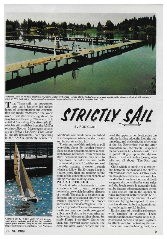
= . = AS 8, ER) Oe ee Eg ’ wet > * elA coll s ae “” ‘ * Surprise Lake, in Milton, Washington, home water of the Gig Harbor MYC. Today’s surprise was a noticeable absence of wind! (Good day to have an R/C tugboat on hand, rigged to retrieve becalmed sailboats! wen). Photo by Rod Carr. hat “front sail,’ as newcomers often call it, has provided endless hours of contemplation and construction for model yachtsmen the world over. I first started writing about jibs way back in the early ’70s in an article entitled Interesting Tips About Jibs (1), which is still available from the AMYA reprint collection. More recent articles are It’s What’s Up Front That Counts (2) and Jibs Revisited (3), both appearing in the AMYA quarterly newsletter. Author’s EC/12 “‘Foxy Lady IV” on aclose reach shows mainsail and jib leeches parallel, sign of good sail set. Very little heel indicates proper sail trim for conditions. Ron Nolz pic. SPRING 1989 By ROD CARR Additional comments were published in a companion article on storm sails and heavy air sailing (4). The intention of this article is to pull everything about jibs together into one place so that newcomers have a comprehensive reference from which to start. Seasoned readers may wish to track down the older material. With that in mind, you will find that some of the older material is woven through what is to follow. But if you are like me, it takes more than one reading before some of the concepts seem capable of taking root and making sense. PARTS OF THE JIB The first order of business is to make a serious effort to learn the proper nomenclature which describes all parts of the sail. The goal is to be able to understand any article about jibs, whether written specifically for the model yachtsman or found in “‘big boat’’ references. If you don’t know the names of the three corners, or the three edges of a jib, you will always be wondering exactly what folks are talking about. So, study Figure 1 carefully. Notice the tack, the forward lower corner, the clew, the after lower corner; and the head, the upper corner. Notice also the luff, the leading edge, the foot, the bottom edge, and the leech, the after edge of the jib. Remember that the after edge of the sail, the “‘leech’’, is spelled the same as the little beasties who tried to gobble Bogey up in the African Queen…and not Robin Leach, who tells you all about “The Rich and Famous’’! Cloth which is outside of a straight line between the head and the clew is referred to as leech rope. Cloth outside the straight line between tack and clew is called foot roach or foot round. Both are generally controlled by class rules and the leech roach is generally held out by battens whose maximum length is also spelled out in the applicable rules. In general, battens should be 2.5 times as long as the amount of cloth they are trying to support. If leech roach is allowed to be 1 inch, minimum batten lengths are 2.5 inches. Each corner of the sail is reinforced with “‘patches”’ or “‘gussets.’’ These provide additional strength in the highly stressed corners and give us places to attach lines for controlling the sail. Hence, we have the head gusset, tack 9
Dohn Bronson, of Reno, Nevada, has built this beautiful 94-1/2” L.O.A., 16-3/4″ beam, 72-pound displacement model of the J-boat ‘“Yankee.”’ It carries 3300 sq. in. of sail area, and needs a clew tiedown on the jib (see Fig. 3). Photo by Dohn Bronson. gusset, clew patch, clew gusset, or even clew reinforcement. They all mean the same thing. THE JIBSTAY The jib is set on a part of the standing rigging called a jibstay. Usually the jibstay is enclosed in a “‘tabling”’ or hem in the luff of the sail. However, other means of attachment such as hooks or loops of cloth are also employed. However it is done, the sail should be able to rotate easily about the stay. The leading edge should be smooth and free from protrusions that would disrupt the air flow reaching the sail. A stay that runs from the foredeck to the mast, without a sail set upon it, is properly called a forestay. Sometimes jibstay and forestay are used interchangeably, but all this really does is add confusion, so be specific. True forestays are rarely found on model yachts today. They do two things which are detrimental to performance. First, if run to the masthead, they prevent the entire load of the backstay from being carried by the jibstay. We want the jibstay taut so as to have the jib luff shaped correctly. Second, they also prevent the head of the mast from being bowed aft in heavy air to depower the upper mainsail and flatten the midbody of the mainsail. If you have an older boat with a forestay still fitted, cut it off and you’ll immediately start moving faster! The foot of the sail is generally attached to some sort of a solid member called a jib boom or jib club. When only the tack and clew are attached, the sail is said to be loose-footed. Constraining the entire length of the foot to the boom is rarely done in other than scale models due to the difficulty in continuing the smooth airfoil shape of sail down to the boom itself. 10 The leech is left free-standing, adapting itself to the loading it carries after the sail is set and full of wind. The search for proper leech shape and tension will occupy a model yachtsman for the rest of his career! The quest for control of the leech has led to the occasional use of the jib club topping lift or leechline, as well as a large number of special jib club mountings of which more will be said later. SETTING VERSUS TRIMMING The proper adjustment of each part of a sail so that it assumes the proper shape for a given wind condition is called “‘setting”’ the sail. Adjusting the position of a properly set sail while underway, to allow for the relative wind and the desired course, is called “‘trim- ming.’ On most R/C boats, setting of the sails occur before launching the boat, while trimming is carried on while sailing. One would set his sails to account for heavy air, and then trim them to advantage on the water steering around the course. Trimming is accomplished by the use of running rigging called the jib sheet, while setting is done with the other lines which are attached to the corners of the sail, the jib club, and the jibstay. It should be pointed out that some classes do not prohibit the setting of sail tensions by R/C. Remote adjustable foot tension and luff tension has been tried and skippers seem to either swear by its capability or swear at the equipment. SETTING THE SAILS The basic control on tension of the luff is the jib halyard, or jib downhaul. Depending on the height of the rig, one is fixed while the other is made adjustable with a simple bowser. Tension in the luff is used to counteract the pressure of the wind on the sail. As the wind blows, it tries to move the point of max- imum curvature aft, so tensioning the luff of the sail pulls the draft forward. Arrange your boat so that the jib luff tension can be varied using one hand, and without having to take the boat out of the water. In that way, you will be able to make small changes between each heat and keep your sail “‘set’’ in step with changing wind velocities. I tend to use a very simple arrangement shown in Figure 2. The control on tension along the foot of the sail is the clew outhaul. If too tight, the clew outhaul can make the foot of the sail almost completely flat. If too loose, it can make the foot so baggy that the boat will not be able to “point” or sail close to the wind. Note that there needs to be a direct, unyielding vertical connection between the clew grommet and the jib boom. Were we to use only the outhaul, a puff of wind could cause the clew to rise, unrestrained in the vertical direction by the outhaul. When this happens, the foot of the sail flattens and the leech falls off and opens up, allowing the wind to spill from the sail. Figure 3 shows a simple way to control the clew position. Various mechanisms have been designed to maintain control of clew position while being easy to adjust along the boom to control camber or flow in the foot and the lower half of the sail. I have a collection of dozens of ways that this problem has been addressed, and will do an entire article on them at some point in the near future. The amount of fullness or ““camber’”’ or “‘draft’’ in a sail comes from two sources. The easiest to see is the additional curvature which enters the sail when the clew outhaul is slacked. A good starting point is to begin with about 10 percent maximum camber located approximately 40 percent of the U.S. BOAT & SHIP MODELER
Gr UGS | ewes TI GENERIC JIB SAIL B ere HALYARD BOWSER | 40% ee 60 | \TACK A CLE MAST sl ~ 10% Sep ea — oO; FOOT ie _ <== way aft of the luff. (See Figure 1.) The second source is fullness built into the sail by the sailmaker. This is extra cloth provided in the luff curve, and in broadseams or tapered panels. This second type of fullness cannot be removed froma jib since the jibstay can only be made straight by tension. Tensions in the luff can move the point of maximum draft around a bit, but can’t eliminate it. About 50 percent of the jibs I see are cut with too much draft. When viewed in light air, with a taut jibstay, a good jib should appear too flat (about 5 percent camber). To give the sail more belly, simply slack the backstay. The jibstay will then sag, and the sail will get fuller. A jib that is too full will backwind the mainsail and will not allow the boat to point well. Before going further, we need to make sure that we are dealing with a jib which is within the rules of the class that we plan to sail in. In most classes, there is some kind of a control on how high up the mast the jibstay may be attached. In virtually all cases, the jibstay is defined as the leading edge of the jib and its extensions. A ruler laid along the upper part of the sail will give a good account of just where that intersection is. Play it safe, and do your physical attachment at least a half inch below that point. Measurers should not SPRING 1989 ~ —— be asked to split hairs, and you would not want to have to rebuild your rig ten minutes before the first race starts. Figure 4 shows an arrangement which violates the rule and illustrates the point. THE JIB AS A PART OF THE SAILING SYSTEM Every part of a sail boat has some sort of a relationship to every other part. We can say that all the parts together form a “system.” Understanding all the parts require us to perform systems analysis. Depending on which part we are studying, that part may be related to many sub-systems all at one time. We need to deal with one sub-system at a time to keep from getting confused. An excellent reference which shows many of these interrelations is the recent A Manual of Sail Trim by Dr. Stuart Walker. It has some excellent diagrams which illustrate concepts discussed. As an example of this systems approach, let us go back to the jibstay. We have seen that it has a primary mission as the support for the leading edge of the jib as the jib luff. But at the same time, it forms a key part of another system, the standing rigging of the boat. Without the jibstay, the mast will fall over backwards! In the fractional rigs we use (rigs where the jib stay ter- minates below the mast head and there is no separate forestay or headstay), the location and tension in the jibstay has a major control on mast shape. Mast shape is important to the set of the mainsail. At the same time, the camber in the jib is impacted by the jibstay tension, a loose stay allowing the sail to be fuller. How the jib club can swivel is also linked to jibstay tension, as is leech tension. So you can see when you tighten down the backstay to tension the jibstay, you can simultaneously cause the following: 1. The jib camber is reduced so the sail is flatter. 2. The jib maximum camber point moves forward so that the sail is better for acceleration, but not as good for top speed. 3. The jib club tension increases for the offset swivel kind of mechanism which is most common. As tension in- creases on the leech, the slot between the jib and main closes up. 4. A smaller slot and a tighter jib means less weather helm. The jib holds the bow of the boat off the wind more, and the boat is less likely to follow puffs of or changes in wind direction. 9. An increased leech tension means there will be much more difficulty in maintaining wing and wing position when sailing to a run. 11
ales 2) CLEW OUTHAUL Se lth CLEW OUTHAUL the flow of air is parallel to the surface of the sail. It is in this mode that the jib must be tuned to work with the mainsail. We'll discuss that interaction and the role played by the “‘slot’’ between the mainsail and jib in a subsequent article. On each of these points of sail one should have a picture of a positive pressure exerted on the windward side of the sail and a negative pressure on the leeward side. The wind is trying to press the sail downwind, and it is the restraining influence of the jib stay, the jib club, and the other rigging which controls the shape of the jib and forces it to deliver up its wind force to the benefit of the skipper. In some ways, the jib can be diouehe There are more, but I think you get the idea. Tweak one adjustment and a number of things are put into motion. The boat is now substantially different than what it was before you tightened the backstay. However, don’t be discouraged. This interrelated nature of the parts on the boat is one of the real challenges to learning to sail well. Any configuration is a compromise of settings. You have to sort out the conditions and decide whether the boat should be set to point close to the wind, or whether the existence of waves and a chop would make it better to foot a little off the wind and have more power and momentum to punch through the waves. Good skippers are willing to exercise their brains to try to sort this kind of stuff out. I find that a notebook is a big help, and at the end of each sailing day I will spend 10 or 20 minutes noting the conditions, the things I did well, and the things that didn’t work so well. It is amazing how much there is to consider, and my memory simply doesn’t have enough reliability to keep it straight from one week to the next. THE POINTS OF SAILING It is not the intention of this discussion to explore the details and complexities of aerodynamics which are the meat and potatoes of fluid dynamicists. Entire books have been written about the airflow around the jibs and the interaction of the jib with the mainsail. I would recommend such references as C.A. Marchaj’s Aero-Hydrodynamics of Sailing or Wallace Ross’ Satlpower asa good sampling of what is available. In each instance, the author works to 12 present his theory of airflow and suitably illustrates with diagrams and photographs with swirls of smoke tracing the trajectories of the air movement. Each author seems to have his own pet analogy, his own favorite way of trying to explain the somewhat unusual fact that a curving piece of cloth can bend the wind, and, by so doing, produces a force useful in propelling a hull forward. For our purposes, simply appreciate that when the air flow passes down both sides of the sail, a pressure differential is set up (the windward side is high pressure and the leeward side is lower, or negative pressure), and that difference allows a force to be generated by the sail. This process is seen most simply when the boat is on a run, moving directly down wind. The wind strikes the sail which has been set perpendicular to the centerline of the boat. Just like a leaf being pushed, the sail goes downwind, dragging the boat with it. Now as the boat comes around on a reach and sails across, or at 90 degrees to the wind, the air flow is more parallel to the sail. Indeed, knowledgeable skippers choose their course and then let the sails out until they just start to shiver. This reduces heeling and produces the most drive from the rig. Sailing with less heel is not so exciting looking, but it is faster and more efficient. Finally, the skipper brings the boat up close to the wind with the sails sheeted in almost to the centerline. While beating to weather, the sail is acting like a vertical airplane wing, and of like one of the leading edge flaps that you see droop down during takeoffs and landings of aircraft. The purpose is to increase the camber or overall curvature of the wing/sail and thereby increase the amount of lift/thrust available. One must be careful to make sure that the increased complexity of the airfoil/sail does not cause extra drag to negate the overall increase in efficiency of the arrangement. BOAT BALANCING WITH THE JIB The jib may be used as a tool for balancing the sailboat while going to weather. Imagine the sails on a boat to be like the feathers on an arrow. With The skipper of F609 needs to add clew tiedowns to each sail. Also needs to treat his sails with more care, as they are getting creased, which will severely reduce their efficiency. U.S. BOAT & SHIP MODELER
the feathers all the way aft on the ar- row, the shaft flies into the wind (caused by its own movement through the air) with little wobbling. If the sails were all the way aft on a sailboat, the boat would simply luff up head to wind Tee SEES JIB STAY GEG iT and stay there. Move the feathers closer to the front of the arrow and it will become less and less stable. The sails will act in much the same way. If the sails are too far forward, the wind will blow the bow of the boat off the te wind, resulting in lee helm, the tendency of a boat to fall off the wind of its own accord, which is an undesirable characteristic. Here is where the ad- TRUE INTERSECTION can be very helpful. If while sailing you desire to point higher for a bit while not losing speed excessively, simply slack the jib a bit and the effect will be as if you moved the rig aft. The mainsail will now push the stern around, the boat will point up higher, and eventually the jib will start luffing. Pull the jib in again (not much, about an inch of sheet is plenty), and ASSUMED justment of the jib using a trim function _ ERROR INTERSECTION : = v iV / | | ee al TOO HIGH, | VIOLATES | CLASS RULE OE the boat will fall off the wind, increasing its speed. Both these changes of direction have been accomplished without touching the rudder! You can point when you want, and you can foot when you want. And you can do either without losing precious speed by fiddling with the rudder. CONTROLS ON JIB SHAPE The most obvious characteristic of jib shape is the sail outline. Each class rule specifies certain dimensions which control either the lengths of the sides of the measured triangles (EC/12), or else the total area allowed in the measured triangles (M, A, 10R). Additional rules provide for areas beyond the straight line edges, usually called “‘roaches’’ or “rounds,” control the width of the heads of the sail and describe the place- ment and length of battens which support the extra cloth found in the roaches. The sailmaker is then free to produce a Sail which will measure in conformance with the sail outline, and in addition will take up an optimum shape when filled with wind. When a jib is held horizontally by each of its three corners and stretched tight, gravity will pull a natural curve into the mid-part of the sail. This extra cloth, called ‘‘camber’ or “‘flow’’ was designed into the sail by the sailmaker to produce the smooth airfoil shape required for efficient sailing. Now, when full of wind, a sail will naturally stretch or deform a little. (This is more true of cloth sails like Dacron, and almost untrue of Mylar sails.) Sailmakers take advantage of the natural ability of sail cloth to stretch when SPRING 1989 \ sev \ See they make “single-panel’’ sails. In single-panel sails, the camber comes from a combination of wind pressures and a bit of extra cloth cut into the luff of the sail. For the mid to upper wind ranges (i.e., 5 to 15 knots), single-panel sails can be very efficient. I have always believed that the smooth surface of single-panel sails contributes substantially to their performance. My ex- perience in sailing against Kelly Martin, three-time EC/12 ACCR winner, is that once the wind gets past two knots, his mylars and my dacrons are equal. Unfortunately, he is a better skipper than I am. The remainder of the competitive fleet is almost totally mylar, and the skipper differences are bigger than sail differences for I can usually stay in front of most of the fleet. (Though I'll admit that the margins are Shrinking drastically and I’m getting scared of some of these new “hot dogs.’’) Single-panel sails are a direct result of the man hours which have to be lavished on them. However, in the lowest wind ranges, dacron does not fill out like the mylars do, and generally suffers on the lightest air days. A major ee benefit of single-panel sails is their capacity for being set almost completely flat as is sometimes required in very heavy air. This allows the boat to be trimmed effectively to avoid the impact of too much heel, or too much weather helm. Broadseaming puts more shape into an essentially single-panel sail by the use of what a dressmaker calls “‘darts.”’ Broadseamed sails work out to be half way between the single-panel and fully paneled sails in price and ease of adjustment. Darts are usually put in the luff of the jib, with sometimes a small tuck taken in the tack or foot. The sailmaker is trying to preserve the adjustability and the smoothness of the single panel, yet introduce the fullness and inherent camber which is found in the fully paneled sail. Luff curves are usually straight lines. In light air, extra camber is placed in the sail by allowing the jibstay to sag a bit, letting a little extra cloth move back into the body of the sail. In heavy air, all the camber due to broad seaming remains in the sail, for Coritinued on page 24 13
Electrifying News from OCTURA MODELS. INC. Pioneer Producer of Proven, Precision, Performance Propellers for R/C Model Power Boats! For electric powered boats, using direct-drive with .125 diameter propeller shafts, OCTURA now has 940 motor available 10 metal propellers. These are intended for use on 540 and 05 motors as well as the special wind motors. Install an OCTURA propeller on your direct-drive boat and you'll be amazed at the performance difference. Also available is a drive dog, the OC4D. All are left hand rotation unless otherwise noted. Available in Silicon Brass, Beryllium Copper, or Aluminum at the same price! THE R/C MODEL BOAT PROPELLER PEOPLE ...SINCE 1954! Order direct only if not available from your local hobby shop. Add $1.50 total for shipping. lll. residents add 7% ales tax. use tabs glued into the cowl front, slipped into slots cut into the hull, coupled with kitchen cupboard door latches to hold the cowlin place. This is an easy boat to paint. Prepare the hull by sanding lightly and cleaning with lacquer thinner. Use a two-part, fuel-resistant paint. With the large cowl and deck areas, you can use your imagination and many of the available decals and stickers to come up with an original finish. The boat comes with a selec- tion of Steve Muck decals, which look quite nice on the finished boat. DRIVING THE CAT The Picco engine was coupled with an OPS .29 to .40-size tuned pipe. This engine was very tight, so several tanks were run through at a rich needle set- ting. An Octura X440 propeller was first tried, and until the engine broke in it was hard to develop any speed. Once the engine could be leaned out, both the Picco and the Steve Muck cat started to show their potential. At first, the cat would bounce, porpoising on the 0930 1427 X427 05 Ain a Cobalt 40 hot wind ni torque { { Panel SUPPLIES 1930 X432 X435_ 7351 N. Hamlin Avenue straights. However, as the engine developed more power, pushing the cat faster and faster, the hull rode higher and smoother. Turns are quick in either direction. This cat does not have to slow down to turn. Ina race you can go into the corner at full-tilt, feed in rudder, and the boat just turns with no tendency to roll, spin out, or hook. However, the hull is so responsive that it is possible to turn inside the buoys instead of carving around them. This little boat has raced in three events. At first the engine was very tight and did not develop the speed to be competitive. During the first two contests, I was a little disappointed in the engine-hull combination. However, at the third contest this boat ran in the 3.5cc Offshore event. As the engine continued to break in, the speed improved to the point that we began to lap several of the competitors. This hull shows exceptional speed potential with no tendency to blow over. If you are looking for a good Offshore Il p> Kit includes Decals Shown > Uses Hardware Set #69 Manufacturer of Precision Quality Cable Nuts & Tuned Pipes. 24 $8.95 each 9.25 each 12.00 each 1.75 each » OCTURA MODELS, INC. > Joined Deck & One Piece Cowl p> Engine Bearers Drilled & Positioned For 4” Mount 6003 Daven Oaks Dr. Dallas, TX 75248 214-380-9274 1630 0937/3 _ OC4D Drive Dog SHOCK WAVE II OMEWis MIUCIS ric soars CTURA X430 X430RH PERFORMANCE REDEFINED SPARTAN GRAND PRIX 45 SPORT CLASS| & The R/C Model Boat Propeller People! Send *1.00 For Catalog U.S. NAMBA NATIONAL WINNER ¢ Skokie, IL 60076 or Enduro boat in the 3.5cc size, this Steve Muck design is the boat for you. If you are looking for a hull to race in the 3.5cc hydro class when the water is rough or the wind is high, this Steve Muck design is the boat for you. If you are looking for a stable little boat that is easy to set up and cheap to run, this Steve Muck design is the boat for you. I would not hesitate to recommend this design to both beginner and avid competitor. The P-5 engine is more than adequate to power this cat and should prove to be very competitive. A beginning boater will enjoy this catamaran using a less-expensive engine, such as the Picco standard 21 Ma- rine. The boater wanting to race will enjoy the P-5 and Steve Muck 20 Spirit Catamaran. ° EO Tike FT RE I Oe Strictly Sail … Continued from page 13 a taut forestay matches the straight luff curve originally cut. I hope this discussion has not proven too exhausting. Fundamentals of the working of your sails are critical to tuning your boat for best performance. If you don’t want to think about what you are doing, you will spend a lot of time at the back of the pack. To learn about sails and wind and how they interact takes no money, only dedication anda willingness to approach a complex subject with a goal of improving your performance. Next time we will continue our discussion of jibs with a consideration of the all-important concept of leech tension. We will look at ways to control the outboard end of the jib club and present some rather amazing devices invented to maintain jib shape in spite of all odds. U.S. BOAT & SHIP MODELER
Complete Fibreglass Kit of this 42inch Tug model with many optional parts including metal crew castings. For steam or electric power and model R/C. We also build boats. The 1/50th scale 6 ot her fibreglass model of the Steamboat “Delta Queen; A quarter scale 61inch gas powered “Cha rger. “EXDprese Cruiser; A 1/96th scale C-2 cargo ship; Two R/C sailing yachts- ~The East Coast 12 meter and the 50/800 AMYAclass yachts. Also we are now building the new 61inch Big Bunker Boat. This is an Atlantic coast Sea Going fishing trawler. Fibreglass hull/deck with optional parts. All model boats have plans and parts available separately. For full details,color photos and prices, please send $3.00. Our 27th year of service to the model Made in the yew. yid@° HARTMAN FIBREGLASS R/C BOX 86, 233 MELROSE ARGENTA, ILL. HARBOR TUG “DOUGLAS GREG” builder. ST. 62501-0086 Since 1962 by Dwight Hartman— phone 217- 795-2275 —— ‘ ) Remember to send your 1989 dues for the American Model Yachting Association to: Pat Hein, 1884 Campus Court, Rochester Hills, Michigan 48309. It’s the best $20 you’ll ever spend. And as long as you have the envelopes and stamps out, drop me a note and a photo of your latest project. Send it to: Rod Carr, 3011-177th Avenue N.E., Redmond, Washington 98052. BIBLIOGRAPHY 1. Carr, Rod, Interesting Tips About Jibs, AMYA Reprint Collection. 2. Carr, Rod, It’s What’s Up Front That Counts, AMY A Quarterly Newsletter, No. 21, Fall 1975. 3. Carr, Rod, Jibs Revisited, AMY A Quarterly Newsletter, No. 63, Spring 1986, pp. 10 through 19. 4. Carr, Rod, On Storm Sails, AMY A Quarterly Newsletter, No. 63, Spring 1986, pp. 20 through 22. o. Walker, Stuart H., A Manual of Sal Trim, W. W. Norton Co., New York, ISBN 0-393-03296-5. 6. Marchaj, C. A., Aevo-Dyanmics of Sailing, Dodd, Mead & Company, 1979, ISBN 0-396-07739-0. 7. Ross, Wallace, Sail Power, The Complete Guide to Sails and Sail Handling, Alfred A. Knopf, 1975, Hoes Q-394-47151-2. ProCat RE TT Patricia…… Continued from page 19 4) Be certain slide valve rods 33 slide easily into the cylinder steering blocks and also that the slotted ends properly fit the links. Note the methods of attachment of these links and also the con rods. The links use small machine screws that fit very small threaded holes in one side of the slide valve slot and the con rods attach to the piston rod with a nut and shoulder bolt. Fit all these things before you make the final assembly. Thisis the only place I have found the instructions to be less than adequate. Another bag (5) contains piping, gaskets, and the reversing block. Assemble everything carefully, bending slightly where needed, with emphasis on Islight. When the engine has reached the appearance of Abb.5c, you can put some light oil in the bearing cups, on all moving and sliding things, and in both the steam input and exhaust pipes, for at this point you don’t know which is what. If you have access toa 5 to 30 psi air supply, or even the “air out”’ of a shop-vac or air brush compressor will do, hook it up to one of the above pipes with the silicone tubing provided, put the reverse lever straight out (neutral), For 3.5cc Outboards ® LOA – 27” Beam – 11” ® Replaceable parts ® Minimal assembly ® Mold injected ABS plastic @ Fine details & sharp corners @ Built-in radio & gas tank box ®@ Sharp sponson edges ® Minimal flash $109.95 Check or M.O. Send $1.00 for brochure _ Requires: 3.5cc Outboard Two-channel radio BEECHWOOD ENTERPRISES Add $3 for shipping & handling MI res. add 4% sales tax 26 53524 Beechwood, Dept. B Utica, MI 48087 Ph (313) 781-8436 and start the compressor. On moving the reverse lever, the engine will start, unless you have a leak or forgot to install those screws in Bag 3 in the unused holes in the cylinders. Moving the lever the other way will cause the engine to run the other direction. You will find that this rotary reverse gear actually gives you a pretty good throttle, as well as a positive forward/reverse. Run the engine perhaps fifteen minutes, stopping occasionally for lubrication. Put some oil in the ‘‘steam in” silicone tube, as there is no wet steam to lubricate the cylinder. The burner and boiler instructions are adequate, so it will be assumed that these components are easily assembled. If you didn’t run into too much trouble attaching the upper and lower sub-assemblies, it should have taken about two hours for assembly. Return the engine instructions and parts list to the box and take out those for the hull. When you are satisfied with the fit of the bottom 18, instructions say it is time to pour ballast. I waited until much later, but it turned out this is the proper time to do it. Get the smallest shot you can, for it takes up minimum space; I used birdshot of about 2 millimeters in diameter. Measure the 700 grams of shot and mix it with as little resin as required to bring the level up over the shot. Pour this mixture into the bottom between frames 14 through 16. If you use the birdshot, this will leave plenty of room for later final trim with the 300 grams remaining. The instructions will cover the hull completion, shaft tube installation, rudder/tiller installation, and forward and rear bulkheads 61 and 98; remember 61 must be removable and 98 fixed. This is also a good time to install the mount for the rudder servo, the servo and the linkage to the tiller. Do not leave the linkage to the tiller attached, for there is a lot of handling to do and Continued on page 43 U.S. BOAT & SHIP MODELER