- Title. Author. Summary

STRICTLY SAIL BY ROD CARR aving spent a good deal of time on the function and geometry of the jib swivel, it is time to move back toward the center of the boat and look carefully at the other major rotational problem—the main boom, its gooseneck, and the associated vang. In Figure 1, we see that the goose- neck/vang arrangement has two interrelated, but separate functions. First, the main boom must pivot and thereby rotate around an axis (A-A) to allow the outboard end of the main boom and therefore the mainsail to be set on either side of the centerline of the boat. Second, the main boom must be prevented from rising (B-B). If the boom rises it will allow the mainsail to twist. The wind will spill from the top of the sail, and useful power to the hull will be lost. Notice that the action of the main boom rising (B-B) is parallel to the axis of rotation (A-A). The forces which transmit them28 SUMMER 1990 selves from the boom back to the axis near the mast make selection of the rotational mechanisms important. On the one hand we want the rotation (A-A) to be friction free. If rotation is considered alone, a simple axle and sleeve bearing would seem to be a reasonable choice. The brass goosenecks produced by A.J. Fisher are of this type. They operate well with smaller yachts such as the Mclass, 36/600 and One Meter. But as the sail area and/or wind strength increases, the magnitude of the lifting force on the end of the boom becomes considerable. It re- sults in a push forward on the top bearing (C), and a pull aft on the bottom or vang bearing (D). The sleeves are now being asked to absorb a substantial sideways or radial load. The result is excessive wear of the axle, and ultimately a rotation which is neither easy nor even. To counteract this tendency, some skip- pers have utilized ball bearings at the swivel points. These absorb the radial load from the boom, allow a tight vang, and do a better job of maintaining easy rotation ofthe boom in light winds. Now before you run out and start cannibalizing the next door kid’s R/C race car for the bearings, remember that you are going to start adding complexity to your boat. With additional parts comes the increased chance for equipment failure. So pause for a moment and take a good look at Figure 2. In 2a, simple screw eyes are used to anchor the vang, with about four wraps of dacron sheet line used as the vang led to a cleat on the boom. The same mounting is used in 2b, but a single-ended turnbuckle makes for adjustment of the vang, and the setting is maintained by a locknut run down the turnbuckle threading to the body. If drilling all these holes in the bottom of the mast
and white 35mm film. Develop the film yourself, it’s really easy and cheap. Then cut up the negatives that you produce and place them in 2×2 slide mounts. By projecting the Axis of Rotation aN > negatives and using a straightedge (Opposite) Adjustable wire vang on Irl has clevis at boom end and ball-and-socket connector at mast end. Brass angle bracket on forward side of mast is explained in Whitten’s article on taking photos from your R/C boat, seen elsewhere in this issue. re course. There are lots of forces that will deform the mast. For the present let’s focus on the forces working in the area of the gooseneck. When. going to weather, the mainsail force will try to lift the main boom. Resisted by the tension in the vang, we are generally left with a forward thrust along the boom into the mast as shown in Figure 3. Note that there are four points along the mast which are controlled by the deck or standing rigging. For Whitten’s 10R No. 39, Ms you make some very revealing discoveries about your mast shape. If you have puthorizontaldraftstripes on your sails, you’ll also learn more about the differences between what you set up at dockside and what is actually occurring out on the race Four wraps of ik dacron line 7 =. fe: ly 7 oe Dacron line FIG. 2A Single-end Turnbuckle Alternate attachment avoids drilling hole in mast near base. Pant #55. a>) — oO FIG. 2B makes you nervous, 2c provides for a neat attachment point. Provision could certainly be made here for use of aturnbuckleifthat is your wish. In all cases shown in Figure 2 I would recommend through-drilling the mast at the forwardmost pair of gooseneck mounting holes. Then use a 2-56 bolt and nut through the gooseneck and mast. The small wood screws usually provided don’t hold very well in the soft cedar and spruce often used for masts, nor are they very trustworthy in the relatively thin wall of aluminum masts like the Goldspar or Pop-Up. Some skippers make the bottom six inches of the mast out of a hardwood which will hold the screws. Others drill pilot holes, run the screws in and out, then inject super glue or thin epoxy to saturate the area around the screws making it stronger. After the glue or epoxy cures, the screws are run inas usual. As masts get taller and more lim- ber, maintaining mast shape while sailing becomes the key to extracting power from the mainsail. There is one mast shape that you can see when sighting down the mast while the boat is lying on the ground. There may be a completely different shape to the mast when the sails are full of wind and the forces required for driving the boat forward are working their way from the sail to the mast and then to the hull. The shape of the mast while actually sailing is really the important one and is a very good reason for taking pictures of your boat while it is underway. Use black US BOAT & SHIP MODELER 29 ,
+p MAIN BOOM / BOW ——+— BABY STAY TENSION GUY—WIRE” RESTRAINER FIG. 4A oe MAIN BOOM FIG. 4B COMPRESSION STRUT aes EO any setting of shrouds, stays and mast step, there are the following constraints: Point on Mast Constraint on Mast Movement Mast Step………. Cannot move forward or aft Lower Side Stay….Cannot move forward JIDSEAY: «.o5.002:- Cannot move aft BackStaye cas. Cannot move forward The bottom third of the mast bows forward as shown by the dotted outline. The mast cannot move at the mast step, nor can it move forward at the attachment point for the lower side stays, so it simply bulges forward between them. When the mast responds to the boom thrust by bowing forward, the first result is a flattening of the lower 1/3 of the mainsail. Cloth that is allowing the camber to form in the sail is pulled forward by the mast. This significantly reduces the power being developed by the mainsail. The lower 1/3 of the mainsail is the major power source, for it can be trimmed for maximum drive while not contributing much in the way of heeling since it is close to the water. Then in domino fashion, the middle 30 SUMMER 1990 FIG. 5 BABY SIDE STAYS LOCK MAST ATHWARTSHIPS of the mast tries to bow aft under the influence of what is happening below the lower side stay point. As this happens, this puts more camber in the middle 1/3 of the mainsail, and by shoving extra cloth into the sail, increases the entry angle, making the sail more likely to luff. The extra camber and the greater height of this part of the sail will contribute significantly to heeling when on the wind. But the jibstay resists a continuation of the aftward bend, so the mast returns to its original position at the jibstay point, and then proceeds forward, only to be brought back by the tension of the backstay. The forward bow in the top 1/3 of the mast removes cloth from the head of the mainsail, flattens the entry angle, and results in less drive and more heel. The top of the sail is working in the highest wind velocity, typically 80 to 90% of what the Weather Service would report with a flow of 50% likely to be experienced somewhere about the middle of the sail. The taller the mast (85-inch rig Mclass skippers take note), the greater the impact on sail performance can be. Narrow chord sails can be severely perturbed by the removal of 1/ 32 of an inch of cloth. But even lower aspect ratio sails as found in EC/12s and STAR 45s suffer if the process is not brought under control. The obvious solution is to provide some sort of restraint, preventing the mast from moving forward. Figure 4 provides a selection of approaches which have been employed. Figure 4a is a simple length of stay wire, swaged to the attachment point on the deck for the lower sidestay on one gunwale, then over some sort of guide fitting on the front of the mast at gooseneck level, and finally to the other attachment point with a turnbuckle for tensioning. The tension in this “baby” shroud will be considerable, so make provision for double swaging sleeves. Figure 4b is a commercially available fitting which acts in compression to form a solid strut between the mast and the deck. Space must be allowed for the jib club to swing through. The fitting needs to be very smooth so as to not snag a whipping jib sheet during a tack or gybe. So far we have dealt with the fore and aft deformation of the mast as caused by main boom thrust. However, the main boom is rarely right on the centerline of the boat. When on areach, the boom thrust will try to
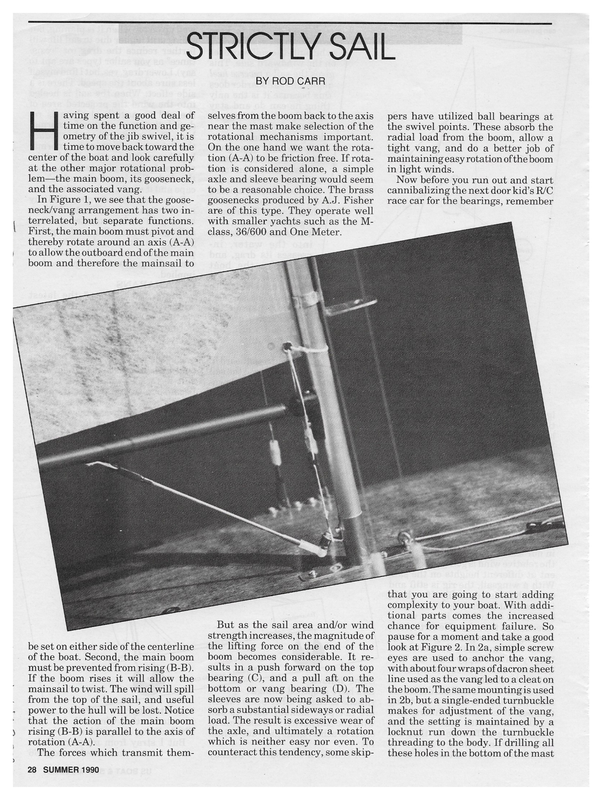
vang is mounted above the boom and carries its load in compression. That is, as the sail tries to lift the end of the main boom, this vang “pushes” back. In so doing, the same force (C) is transmitted to the mast, in approximately the same position. So though this vang is working in compression rather than tension, an equivalent set of forces produces a thrust on the mast and all that we have discussed up to now applies. Short of building a framework of girders and making the mast look like the Eiffel Tower, there are some alternatives for dealing with the disturbing results of uncontrolled boom or vang thrust. One option is to physically sepa-— rate the main boom completely from the mast. A robust axis needs to be erected slightly aft (6-10mm) of the mast. Some sort of outriggers will be needed to stabilize the axis in an athwartships direction and to transmit the thrust to the deck as in Fig- FIG.6 COMPRESSION VANG ure 7. One might consider a tripod arrangement as shown, and provide for movement to match any adjust- bow the mast not only forward, but sideways too. To. prevent that, very short side stays made of solid stock have sometimes been fitted as shown in Figure 5. A simple but effective approach to controlling this unwanted bending and flexingis tomake your mast out of enough material so that it is stiff enough to resist the bending forces which are forced upon it. It may be that a trade-off between slightly greater mast weight and greatly improved sail shape would provide a net in- crease in performance all the way around the racecourse. Photo 1 shows a straightforward arrangement on Irl Whitten’s 10-Rater. The ball link at the mast end of the vang allows the swiveling action for the vang as well as vang tension adjustment. How is the vang tension locked, Irl? And can you tell us how this works in strong winds? For those with the magnifying glass out, the bracket up the mast a ways is a mount for a small camera that Irl sends out on the race course for some excellent pictures of racing action. COMPRESSION VANGS In an attempt to lower the mainsail, reduce heel and gain the advantage of sealing off the foot of the sail, some skippers have experimented with a boom/vang arrangement as shown in Figure 6. The boom is pivoted near the foot of the mast. The ment allowed in the mast placement. The generous bearings found in the typical swing rig mount might allow all the structure to be below deck, with only arobust axis for boom and vang adjustment protruding as shown in Figure 8. The compression vang can be used if desired. The benefit with this configuration is simplicity, less clutter on deck, and the opportunity to build the assembly with sufficient strength for the class involved. US BOAT & SHIP MODELER 31 w s
stick that won’t bend, or you can fiddle with the placement of your rigging. Whatever you try, take some pictures so you can tell if you are making progress. And if you do, send them to me here at USBSM so we can all gain from your experience: Rod Carr, 3011 177th Ave. NE, Redmond, WA 98052. I’m happy to report that the International Yacht Racing Union—Model Yacht Racing Division (1YRUMYRD), which used to be known as IMYRU, accepted and established wl. the new rules for the International East Coast 12 Meter Class. As of this writing, lamnotsurethatourAMYA will award class status to the new \ — —“”} ‘ ) STRONG DECK MOUNT rules, however, if y you have a regular EC/12, your present hull has been grandfathered and you are invited to join the new class by sending a $2.00 bill to the U.S. Class Secretary: Ron aS: SWING RIG MOUNTING KEEL Banner, 115 17th St. SW, Puyallup, WA 98371. The new rule lays to rest all of the disturbing loopholes the old AMYA rules were afflicted with and provides for sailing the boats in their BLOCK present configuration without the hassle of annual rule changes, as has occurred within AMYA. A U.S. National Championship is scheduled for August 25-26, 1990 as a prelude to the World Championship in ofan 1991in Seattle. A second option, which was tried about 10 years ago, was to erect a bipod or A-frame mast and set the mainsail on a vertical stay which runs down from the mast(s) head te the centerline of the deck. Tensioning the stay becomes a challenge, but the curve will be regular, and if some photographs are taken while underway, it should not take much effort for a sailmaker to do a good match between the desired luff curve and the deformation of the stay under load. A third option one might consider is the arrangement of the mainsheet when sailing closehauled. Ideally, the last 1/4 inch of inward sheet movement should cause the vang to slack as the sheet takes all the load of the mainsail leech. At that time, there is almost a complete balance between the sheet tension and the leech tension. Ifthe lead angle of the sheet can be in line with the sail’s leech, there will be practically no residual force pushing the boom forward (see Figure 9). I don’t recall seeing any boats rigged this way, so it might be something to experiment with a bit. In summary, if you want to control your mast shape you can add fittings and gadgets, you can use a broom32 SUMMER 1990 Sail Lift Residual Force go a Alternate Main Sheet Typical Main Sheet eA Tension Sheet \ { N .\ \ FIG. 9 ont Xe |