- How to Build a Sailing Model by the Lift Method, Part II. Thomas Darling.

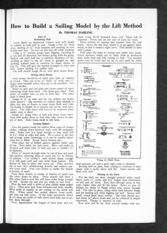
How to Build a Sailing Model by the Lift Method By THOMAS DARLING Part II Hollowing Hull Screw block on deadwood (where lead will finally be bolted) to hold hull in vise. Gauge a line 4%” from sides, starting at 34” from transom and meeting on cen- terline near bow. Do not cut this line off while working. Using a %” outside gouge start digging, traveling in a fore and aft direction, but always going with the grain. Hollow out until hull has a uniform thickness of 1%”, swelling at sheer to the 5g” mark as gauged on, and working toward keel to conform to shape shown in Fig. 11. This will give the needed strength at sheer and them, using 10/32 threaded brass rod. Three will be required. Sweat nut on one end of each for head. Dress bottom of casting and counter bore for bolt heads. Dress the top face, which is to go against deadwood, so that it makes a tight joint. This should be done with a plane. Now place the bolts in casting and solder over heads Cover surfaces which are to make joint at deadwood with white lead and bolt casting to hull. Use washers under nuts on inside and set up on nuts until the white Bun onesr keel. Leave landing for rudder tube. The hull should weigh 30 oz. with deck beams fitted. _ Ss” eee Fitting Deck Beams The other beam is fitted here. Gauge in 4%” at sides and lay out sockets for beams (both places). Dig mortises or sockets deep enough to allow top face of beams to come down flush with side. Cut beams to length, fit in mortise and secure with brass [re top of box, first withdrawing dowels, and remove pat- tern from sand. Note core prints or marks for dowels at bottom of mold. Place three dowels in marks at bottom of mold and slip cover down in place. These dowels will burn a little when lead is cast, but will leave holes large enough for bolt. Secure top and you are ready to cast lead. _ Heat the lead until a sliver of pine sizzles when poked into it. Then pour lead from forward vent hole, steadily filling mold as rapidly as the cooling of the metal will allow. When metal has cooled remove from mold, and take out bolt cores. If the holes previously bored do not show on inside of hull where keel bolts are to go, bore them through. Next, approximate the length of keel bolts and cut Cp betes – ree Ly be aluminum én yp 4 , stig ay £ r ala fareee Sper a _ i Fa | ‘? fs oer 1 = ear Lat] a a) tt t — eta ¥ ane f-—” – = aee el 2.- AF screws jeune F Fetter “SS hates for *a-$° Fu? rews a Croton *a-4 haun-pletes ew hele _ far Se f = fer turn- = buckle b Tube pi, vty mrece — 4 a Strew Tern bushte eve { * Folding Sareeders _ wx +8 & *_* “e —+ > Sree tare end hook in Boom —@:——- Traveller Ss cf dese zs 6 {“hete per heed. Peegt-bee! Bond Stay ond eeiging ‘tind Note – All Ftenge te beef Bross yates ether meterie! is apesi fied. Thies cen be niche! pleted «f desired Fittings for Model Sloop. lead squeezes out and a good tight joint is obtained. Resting hull on pads, trim casting to conform to keel shape with a spoke shave and file. Sand smooth and flush with hull. Putting on the Deck For the deck use clear, straight grained white wood. Have stock %” wider and 1%” longer than dimensions of hull and %” thick. | | | 2 @ > iy a A. f | Tension fest f° 23 8s= | \\ Magulete: re To Give the pattern made for ballast three coats of orange when box is filled. Screw fasten bottom also. Then place top of ballast pattern against under side of top. Bore holes for bolt cores. Bore vent holes at forward and after ends of lead and one in middle, 4″ in diameter. Place 4” dowels through holes in top of box and push into pattern, allowing them to come out %” at bottom of pattern. Use molder’s sand mixed damp enough so it will pack well and ram mold from bottom. Put bottom of box in place and screw_on. Then unscrew a \a Cong (> C) hrote ry se * van sheen Casting Ballast and arrange screw fastenings so it can be readily place: 298 tiem Meat- stop screws. The after beam will have to be removed when rudder tube is fitted. Gauge %” along sides of hull and down from sheer Trim with spoke shave so that sides take crown or camber of deck. Make beam mold to test here. shellac, rubbing down between coats with OO sandpaper oiled. Make core box large enough so that mold will be 114” thick at sides and ends. Fit a cover to the box Sy wy vo (Bert) “ Strew-eye ‘*°”* will be needed. Refer to spar and sail plan and locate center of mast, center of rudder tube or port at deck line. a s holes ————. longer than breadth where they are to be installed. Two One beam goes there. Find A $——5 e => 5 of mes They are to be 14” thick, 4” wide, and 2” measuring from stem head. Lille = pee Geqge-agch Deck beams should be of white pine with 34” camber or crown. Grruwas r =—— 5 Bore hole through beam in line with rudder tube and fit the latter. Refer to plan of fittings for shape of flange where tube comes through hull. Put tube in place, using white lead between flange and the landing left when digging out hull. Secure with small, round head brass screws. The tube should project about 4%” above beam and can be trimmed to length afterward. Flange is sweated to tube. Bore hole and fit the deck around rudder tube see-
54 ¥ACEH projects at bow and <== extradeckstoinck place ing thatTack stern. with brads, temPA ___May, 1924 [TM—, for the mast square. Square one end, la, off length and square other end. 17 4 porarily, fore and aft, while you mark 3%” outside of hull. Trim deck to this line and make outline fair. ¥ é Gauge off centerline on side, to be used after side of mast. when shaping spar. Give underside of deck and inside of hull three coats of spar varnish, allowing it to dry. Now put deck in place and fied diameter, at heel of mast. Also lay out circle at mast head. Now from point gauge ' pencil line lightly for course of screws around sides and stern. Allow to come in from side of hull 4”. Bore holes, one inch apart, for 2” No. 2 flat head brass screws. Inspect joint of deck and hull for fit, remove deck, and apply white lead or varnish to edge of hull and deck and replace the latter. Press deck down at lowest point of sheer, bore with brad awl for screws and drive same. Fasten on opposite sides alternately, so that deck is secured on both sides at the same time. Work fore and aft, letting screw heads sink slightly below the surface. Then trim deck at sides, sand smooth and varnish. Making Fittings on mast where headstay and shrouds are cated, taper front and sides of mast with gradual curve to mast head. Remove corners from heel to head, making spar oc! gon in section. Round off all corners, keeping mast a uniform diameter from keel to place for shrouds, and tapering from there to head. After side of mast should be straight and gauge line should show plainly. Dress piece for boom square. Square one end, lay off length and square other end. Gauge off line on side to be used as top of boom. Measure in one-third of length from outboard end and square mark around. Lay out circle outboard end and one at inboard end. Starting ai one-third mark, taper boom on sides and bottom, working toward inboard end, with gradual curve. Repeat, work- Refer to plan of fittings and note the use of each piece and know where it is to be located on boat. Anneal stock by heating and quenching. Make bowsers (two are required) by filing brass stock ing toward outboard end. to specified width. Lay out holes, center punch and drill. Cut to length and file corners round. Take off all burr edges and polish with emery cloth and Brillo. The mast step should be laid out to specified dimensions. Notch to receive mast. Center-punch holes, and lacing hole. Make jib clud in same manner. Steam and bend mast. Sand out all tool marks and varnish mast, boom, and club, giving three coats. drill. Shape notch and round all corners. Lay out stern band, file end for hook and shape end for stem head. Shape hook. Place against stem and bend hook to take angle of head stay. Refer Spar and Sail Plan. Make plate diamond shaped to be fitted over rudder tube and secure to deck with screw at forward and after ends of plate. Chain plates (two are required) for shrouds can be made by opening small screw eyes passing through holes in turnbuckles and closing eyes again. Turnbuckles can be obtained at model makers’ supply store. Two will be required. Make ferrules as shown. Fit small one to inboard end of boom, other to forward end of jib club. Gooseneck made by taking small screw eye, bending end of brass wire as shown and closing eye on wire. Length of main traveller 24”; jib traveller 6”. Tension rack made of mahogany, varnished. Regulator made by filing shoulder at each end of threaded rod, boring holes in angle clips, and sweating rod to clips. Put nuts on before sweating. Bore holes to secure to deck. Polish. Rudder is made of wood. Secure to rod for rudder stock with four 4” No. 2 F.H. screws. File screw heads to conform to shape of rudder stock. Work shoulder at heel of stock to fit socket in keel. Procure piece of brass bar stock and work out tiller as shown. Bore holes for rudder stock, main sheet and rubber band or spring. Bore and tap hole for No. 2 machine screw, allowing enough length on rudder stock to clear regulator when in action. Tiller points aft. Two small screw eyes and one screw hook are required for sheets on booms. Make staples or lacing eyes of rigging wire. Spar Making ' Procure pieces of clear white pine or spruce with straight grain for mast, boom and jib club. Dress piece as Do not remove line Lay out circle, speci- Work spar to octagonal shape and finish as in mast. Fit ferrule at inboard end and bore for gooseneck and Sail Making Before attempting the sails let us become acquainted with the names of edges and corners of mainsail and jib. The mainsail has three edges. They are called luff, foot, and leech. The luff runs along the mast, the foot is spread on the boom and the leech is the after edge of the sail. The edges of the jib are named similarly, the luff being at the head stay. The corners of each sail are called by the same names The lower after one is called the clew. The forward lower one the tack and the top corner the head. Use a large sheet of paper as a layout floor and locate the head, clew and tack of the mainsail. Move clew mark %-inch closer to tack to allow for stretch in finished sail. Allow %-inch for stretch on luff. Connect these points with straight lines. At a point one-third way up on luff measure out 4%-inch, sweep in curve from head to tack. These fullnesses are called from tack roaches. At point one-third way along foot to tack. The leech is laid out as shown on drawing. measure out 1-16 inch and sweep fair curve from clew. Layout head clew and tack of jib. stretch on foot. Allow %-inch for Connect points with lines. One-half way along foot measure out 1-16 inch and sweep fair curve from clew to tack. Use best grade of Lonsdale cambric and spread over marks on floor. See that selvedge of cloth is parallel with line drawn from head to clew. This applied to both sails. Keep outside of marks far enough so that selvedge can be cut away. Secure so cloth cannot shift, and mark same. Cut 14-inch outside marks for luff and foot and 3-16 inch outside for leeches. Crease or rub to marks all around and turn tabling or hem in double. This will give necessary strength. Have a row of stitching on edges of sails running from head to tack and to clew. Put one row only on leeches. place same. Lay out batten pockets and The sail is then ready for bending.
Some Pointers on Planked Construction for Models f | i / // ; Her general dimensions are given in the enclosed article. | | / j j j j Lines of Pclka Dot, cwned by E. A. Bull, which won the International Model Yacht Race in 1922. j j Here are some questions pertaining to the construction of Polka Dot, described in our February issue by J. L. Wilson, and the answers thereto. What means are taken to make a planked model watertight ? The watertightness of Polka Dot is almost entirely a result of good workmanship, for none of the earlier methods of calking, the use of a filler, or a lining with muslin, etc., was employed in the construction of this model. Her planks were well laid, closely fitted, and with square seam edges. After removing the model from the dummy and finishing the fastening and fairing, the inside and outside of the model received an application of linseed oil to prevent either swelling or drying out, and finally the usual varnishing for protection and finish. This varnish was applied inside as well as outside and a good water-resisting varnish was used which was heavy enough to fill ordinary seams of such character as are found on model yachts. Compared with Wetona, a _ previous model by the same builder, and one which is entirely lined with fine muslin between framing and planking, Polka Dot is practically as watertight as the older hoat. Wetona may be considered a standard, for she has never been known to “take a drop.” We have never seen a case in which glue was used on the seams, but have seen poor workmanship covered up with a filler, consisting of white lead (powder) mixed with shellac to the consistency of paint, applied in one or two coats to the inside of the model. All such methods, even the excessive use of glue, add considerably to the weight of the hull and are undesirable What are the approximate dimensions of Polka Dot? Length of hull (exclusive of bowsprit), Length of bowsprit, Beam at load waterline, Draft, Freeboard amidships (approximate ), 3 inches Weight, 42 pounds Total sail area, 3075 sq. in. Rig—Gaff headed mainsail with two headsails amie and a club topsail ’ Rating — Univer sal Rule, 459 (limit of class 46’) / fs 72 inches 2 “ 13%“ 16 Sail plan of é Polka Dot