
- How to Build a Sailing Model by the Lift Method. Thomas Darling.

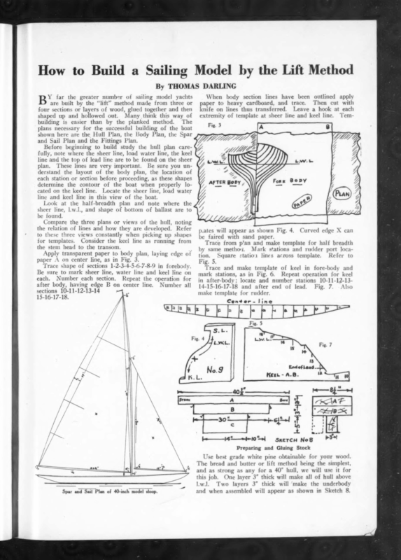
How to Build a Sailing Model by the Lift Method By THOMAS DARLING When body section lines have been outlined apply paper to heavy cardboard, and trace. Then cut with knife on lines thus transferred. Leave a hook at each Y far the greater number of sailing model yachts are built by the “lift” method made from three or four sections or layers of wood, glued together and then paper A on center line, as in Fig. 3. Trace shape of sections 1-2-3-4-5-6-7-8-9 in forebodly. Be sure to mark sheer line, water line and keel line on each. Number each section. Repeat the operation for after body, having edge B on center line. Number all sections 10-11-12-13-14 15-16-17-18. biti V2 rr fFaw \ Ul A Tem- 8 Nc Wan Fig. 3 r \ \\ Y, \ AFTER BoDy | Na Before beginning to build study the hull plan carefully, note where the sheer line, load water line, the keel line and the top of lead line are to be found on the sheer plan. These lines are very important. Be sure you understand the layout of the body plan, the location of each station or section before proceeding, as these shapes determine the contour of the boat when properly located on the keel line. Locate the sheer line, load water line and keel line in this view of the boat. Look at the half-breadth plan and note where the sheer line, |.w.l., and shape of bottom of ballast are to be found. Compare the three plans or views of the hull, noting the relation of lines and how they are developed. Refer to these three views constantly when picking up shapes for templates. Consider the keel line as running from the stem head to the transom. Apply transparent paper to body plan, laying edge of extremity of template at sheer line and keel line. % shaped up and hollowed out. Many think this way of building is easier than by the planked method. The plans necessary for the successful building of the boat shown here are the Hull Plan, the Body Plan, the Spar and Sail Plan and the Fittings Plan. p.ates will appear as shown Fig. 4. Curved edge X can be faired with sand paper. Trace from p’an and make template for half breadth by same metho. Mark stations and rudder port location. Square statio: lines across template. Refer to Fig. 5. Trace and make template of keel in fore-body and mark stations, as in Fig. 6. Repeat operation for keel in after-body; locate and number stations 14-15-16-17-18 and after end of lead. 10-11-12-13- Fig. 7. Also make template for rudder Center. line ~ = PPE RERE RS” Fig. — ‘L a : : tained 5 p —~}-63″ Gio -_——14—+#-10″“»} ¢ [ aceex a S i oe SxercH NoS a Preparing and Gluing Stock Use best grade white pine obtainable for your wood. The bread and butter or lift method being the simplest, and as strong as any for a 40” hull, we will use it for this job. One layer 3” thick will make all of hull above l.w.l. Two layers 3” thick will ‘make the underbody Spar and Sail Plan of 40-inch model sloop. and when assembled will appear as shown in Sketch 8.
YACHTING April, 1924 Layer C will be placed on edge. If unable to procure stock of this thickness, blocks can be built up in 1” lifts. This will enable builder to see all waterlines as drawn on plan. These waterlines are not necessary for our purpose, as the points we are concerned with are the sheer line, load water line and keel line at each station or section. Dress faces, edges, etc., of each block square smooth. A jack plane is best tool for this purpose. blocks in positions shown in Sketch 8 and make that they fit true preparatory to gluing. Secure and Lay sure tem- End ef Leod MKaer-F.8. porarily by toeing a couple of brads in ends of stock as shown. * : = Seeee Puan Mair Bacaern Plan Lay out length of load water line on joint between A and B block and locate amidships section (station 9) on same. Draw brads in block C and move out to edge of block B (broken lines shown in Sketch 8) and secure in position, Square line on three blocks from top face of A block. . Carry this square line across top face of A block and down other side. Gauge centerline on three blocks. Then with midship section, or Section 9, as a starting point, lay out stations 8-7-6-5-4-3-2-1-0 forward, and 10-11-12-13-14-15-16-1718 aft, by placing half breadth template on centerline, and transferring marks from same to the wood. Square all station marks on top and sides of A block, and on sides of B and C blocks. Number all stations on top and sides of blocks. Place template for keel in forebody (shown Fig. 6) being careful to locate properly at load water line and stem head, and trace outline of forebody. Note that station marks on blocks and template come true. Mark forward end of lead. Obtain outline for shape of afterbody keel line in same manner. Mark after end of lead. Now take wing dividers and pick off sheer heights at each station for sweep of sheer line at side of hull and lay off on block. By securing a batten, which passes through these points, with small brads, a fair line can be drawn in with pencil. Lay out top of lead line and dress parts that have been roughened by saw cut so that they make a close joint. Apply hot glue to each part, put single thickness of newspaper between and clamp in original position. Later this joint will come apart easily when the pattern is required to mold ballast. Lay out shape of bottom. a 1a i i Hull and Body Plan of 40-inch Racing Sloop. v Fig. 9 Fig. 10 Fig. 9 shows appearance of our blocks, marked, and ready for gluing. Note C block is back in original position. Apply glue to each side of joint and clamp block back in position. Check to see that station lines are in proper relation to each other on each block. Any good water(Continued on page 341)
YAGHTFING , oe – ~ April, 1924 Building a Model Yacht | K, H. SCHEEL e : alo Pler One Rooms SEATTLE, EDGAR F.) HANFORD, M. S. NV. A. s , 158 ,Ashmont St., Boston Puons, TALBor 3332 T. B. F. BENSON Naval Architect and Yacht Broker Leader Lane and Colborne Strect TORONTO, CaBLE ADDRESS ONT. “BINGLEY’’ good results. i aft. This can be Wone on tand saw if New : convenient to a, mill, or with a turning t TORONTO Mass. work. EDSON B. SCHOC€CK . Carry station lines from side to -side across finished keel line and number each one. Saw cut to sheer line and dress smooth. Carry station lines from, Naval Architect and . Engineer Number each sta stem to transom, ‘tion where it crosses center-line. Next, place half breadth,template and Saw-cut to this line and dress smooth with spake shave or plane, squaring down Before going further bore from top. a %” hole 5/16” forward of station 10, another one %” aft of station 10, and another at station 11. Push a 4″ dowel . Yacht and. Vessel Broker 720 Pacific Finance Building side to side and gauge centerline from trace outline of sides of hull. Bedford, Send atamp, for catalog Illustrating fortythree typleal HMand-V-Hottom desians. Every design, now as always, my personal fore and @ saw. Then dress to line.carefully with ‘|’ spoke shave, inside gougé and chisel. Gauge center line from bow to-stern. NAVAL ARCHITECT’ YACHT BROKER with First, saw cut to keel ling 2- —ULS. A . NAVAL ARCHITECT author has used @asein or Casco glue ’ , Yachts, Chartered, Bought & Sold ‘ WM. H. HAND, Jr. (Continued from page 2%) ” proof glue will do for this job. The NAVAL AROHITECT f 341 ‘Los Angeles, Cal. Tel., Lombard 2072 Cable Add., “Murwat” J. MURRAY. WATTS Naval Architect-and Engineer Yacht and Vessel Broker y Office: at 136 South Fourth, St.; Philadelphia in,seach hole to reinforce joint at lead JOHN G. ALDEN Yacht Broker and Naval Architect MARINE INSURANCE TELEPHONE, RICHMOND 148 STATE STREET. 2318 BOSTON, MASS. B. T. DOBSON Naval Architect, Yacht Broker, Marine Insurance New Bedford, Mass. RESIGNE OF SAILING AND POWER AUXILIARIES CRAFT, YACIITS. RALPH E. WINSLOW .4 NAVAL ARCHITECT Atlantic, Mass. River Street Sailing, Auxiliary, Motor and Diesel Yachts. Have’ your next season’s yacht designed 19 years’ experience. Stock plans. COX & STEVENS Naval Architects, Engineers, Yacht Brokers Removed to 25 BROADWAY, CUNARD BUILDING (Morris* Street Entrance), NEW YORK CITY Telephone 2700 Whitehall NAVAL ARCHITEOT and ENGINEER | Yachts—Motorboatsa—Steamers— Schooners—Tugs—Barges of Steel ° or Wood 14 S. Wissahickon Ave., Atlantic City, N. J.. WALTER B. BRASH YACHT BROKER Power BOATS, SAWING YACHTS,” TENDERS ALL KINDS OF SMALL BOATS, MAKINE ENGINES AND ACCESSORIES Send particulars, of your yacht If you wish to sell, or write your requirements if you are in the market. . ESSEX Then place number 9 _ template against block at 9 station,’and remove waste stock until block appears as in Sketch 10, Take inside and outside %” gouges, and with them groove from the sheer line to keel line until template number 9 fits accurately. Jefore starting to groove, color edge of template with black or blue crayons. This color will touch the high spots and readily show where more cutting is necessary for proper fit. The hooks on template – in vise, Fig. 10. ; Then>shape sections 8-7-6-5-4-3-2-1, using this method and afterwards work on sections 10-11-12-13-14-15-16-17- FREDERIC S. NOCK, INC. Naval Architects and Yacht Builders EAST LAYING CONN, GREENWICH, OFFICES: 1%” bit. Rudder BOWES, LAFAYETTE CHESTNUT M.E. AND FIFTH BUILDING: STREETS PHILADELPHIA, PA. SERVICE THAT – DIFFERENT ‘S PHONE, MURRAY HILL 3810 JOHN H. WELLS Naval port or tube, using a D. I. RAILWAY Naval Architect and Engineer Remove waste wood between stations with a 14%” gouge having a rather flat section. You will not have so much material to dig through, when grooving at the section marks, as waste stock is removed following the general contour of the hull. Finish one side first, then the other. Make groove for rudder stock along deadwood and keel and bore for rudder R. UP—REPAIRS—MARINE THOMAS 8 post should be left 4%” wide. E.Lockwood Haggas Designs for ing ballast. will catch at sheer line and keel line. Note Block V screwed on for holding Telephone Granite 1011 or 2599-M now. line. These can be withdrawn later and serve as cores for holes when cast- Architect—Brokerage Yaeht Repairs 23 YEARS BXPERIENCE 347 MADISON AVENUE HARRY W. SANFORD YACHT BROKER 501 Fifth Ave., at 42nd St. N. Y. Telephone, Vanderbilt 0969 “Desirable yachts of all types for sale and charter’ Cut down to all grooves at stations, using spoke shave and block plane, ‘being careful not to go below guide marks, Sand out all tool marks, using number 1% sandpaper and finish with number 00. Shape transom and sand smooth. Then remove pattern for ba]last by inserting cutting edge of chise] at after end and giving a sharp tap. (To be F. T. WOOD NAVAL ARCHITECT Plans furnished for yachts and “commercial vess of all types—steel or wood con- struction. RACING YACHTS A SPECIALTY. 426 Clermont Ave:, Brooklyn, N. Y. continued) ’ GORDON MUNROE NAVAL ARCHITECT See Page 326 YACHT BROKER 66 Grampian Way Boston é YACHT SAILS YACHT AWNINAS, ETC. YACHT FLAGS NEW YORK SAILMAKING CORP. 59-61-63 Sedgwick St. Brooklyn, N. be HON ENR 160- 25