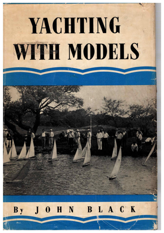
Yachting with Models: How to Build a Champion M Class Model Yacht (1939) is John Black’s practical guide to constructing, rigging, and sailing a competitive Marblehead 50/800 model yacht. Beginning with a short history of the Marblehead or M Class, Black explains the necessary tools and compares three established methods of hull construction: vertical lifts (buttock construction), horizontal lifts (bread-and-butter construction), and keel, rib, and plank construction. Detailed instructions, drawings, and photographs lead the reader through shaping a hull, fitting the deck, painting, making spars and fittings, and selecting and constructing steering gear and sails.
The book then covers rigging, adjusting, and sailing the finished model, including practical guidance for beginners and prospective racing skippers. A final chapter explains how to organize a model yacht club, and the appendices supply a nautical glossary, contemporary M Class rating rules, sailing rules, and directories of clubs and suppliers. Written from the perspective of an experienced designer, builder, champion racer, and industrial-arts educator, the book combines workshop instruction with a historical account of organized model yachting in the 1930s.
Preface. Black explains the educational and recreational purposes of the book and its emphasis on practical construction with a modest selection of tools.Foreword. William M. Carpenter discusses Black’s qualifications and the international acceptance of the Marblehead M Class.Introduction. Eugene L. Cheney introduces the growth of model yachting as a craft, science, and competitive sport.Chapter I: Brief History of the Marblehead 50/800 or M Class. Traces the class from Marblehead’s local pond racing to the 50-in, 800-in2 rule and its recognition in national and international competition.Chapter II: Tools and Equipment for Building a Model Yacht. Outlines the workbench, hand tools, and basic workshop equipment needed to construct a model yacht economically.Chapter III: Describing the Most Popular Methods of Building the Hull of the Model. Compares vertical-lift, horizontal-lift, and conventional planked construction, explaining their advantages and practical difficulties.Chapter IV: Building a Marblehead 50/800 Model by the Buttock or Vertical-lift Method. Gives detailed construction instructions for a Cheerio I hull using vertically laminated wooden lifts.Chapter V: Building a Marblehead 50/800 Model by the Bread-and-Butter or Horizontal Lift Method. Describes cutting, assembling, hollowing, and shaping a hull built from horizontal wooden lifts.Chapter VI: Building a Marblehead 50/800 Model by the Keel, Rib, and Plank Method. Explains traditional framed and planked hull construction, including the keel, ribs, planking, and finishing operations.Chapter VII: Fitting, Marking, and Laying the Deck. Covers deck construction, alignment, marking, and installation to create a neat, functional upper surface.Chapter VIII: Painting the Hull. Discusses preparing and finishing the hull, including painted and varnished surfaces and waterline treatment.Chapter IX: Making the Spars. Explains the fabrication and fitting of the mast, booms, and other spars for the model’s rig.Chapter X: Various Types of Steering Gear for Sailing Models. Introduces the steering arrangements and controls used to maintain course on a free-sailing model yacht.Chapter XI: Making the Fittings. Provides methods for making the small hardware and mechanical fittings needed for the hull and rig.Chapter XII: What to Know about Model Yacht Sails. Discusses sail materials, design, form, and handling considerations before fabrication.Chapter XIII: Making the Sails. Gives practical directions for cutting, shaping, sewing, and finishing the model’s sails.Chapter XIV: Locating and Fastening the Fittings. Covers installing the fittings, setting up standing and running rigging, sheets, kicking strap, jib steering gear, and bending on sails.Chapter XV: How to Sail a Model Yacht. Explains preparing, balancing, trimming, and steering the model for practical sailing and racing.Chapter XVI: How to Organize a Model Yacht Club. Offers guidance for organizing a club and supporting organized model-yacht sailing.Appendix I: Glossary of Nautical Terms. Defines boating, rigging, building, and racing terminology used throughout the book.Appendix II: Model Yacht Racing Association of America Rating Rules for M Class. Reproduces contemporary class measurement and rating requirements for Marblehead models.Appendix III: Sailing Rules. Provides the racing and right-of-way rules applicable to model-yacht competitions.Appendix IV: Names and Addresses of the Secretaries of Model Yacht Clubs. Lists contemporary model yacht clubs and their secretaries as a period directory.Appendix V: Names and Addresses of Concerns Supplying Model-yacht Fittings. Lists contemporary suppliers of model-yacht fittings and related materials.Index: An alphabetical index of subjects and terms concludes the book.
= BOER ERS oe BS z ve = =F �YACHTING WITH MODELS �Above, Cheerio I, with the author. This boat won the World’s Championship for the Marblehead 50-800 class, Hamburg, Germany , 1936. Below, two views of Cheerio II, Eastern Division Champion, M.Y.R.A.A., 1937; and National Champion, M.Y.R.A.A., 1937. (Frontispiece.) �YACHTING WITH MODELS How to Build a Champion M Class « Model Yacht _— er er By Se Se OO OO OO OOS OES JOHN BLACK Director of Industrial Arts, Watertown, Mass.; President International Model Yacht Racing Union; Treasurer Model Yacht Racing Association of America gg New York ET WHITTLESEY HOUSE MCGRAW-HILL BOOK COMPANY, London INC. �Copyright, 1939, by the McGraw-Hut Boox Company, Inc, All rights reserved. This book, or parts thereof, may not be reproduced in any form without permission of the publishers. PUBLISHED BY WHITTLESEY HOUSE A division of the McGraw-Hill Book Company, Inc. ’ Printed in the United States of America by the Maple Press Co., Inc. �ee Ne Ne a a ae at ee ea ee oe Preface Yachting with Models is written as an instruction book. It is to be used for general information about hull construction, types of fittings, the making of sails, and the actual sailing of the model. In this age, much stress is being laid upon the proper use of our increased leisure time. Those persons who have hobbies make good use of their leisure. To many who have not developed hobbies, such an avocation would be most welcome. It is with this thought in mind that this book is written, in hope that the projects described will create a real ambition in the reader to build model yachts. The satisfaction of admiring the results of one’s handiwork will then create the desire to produce more and better work. During the past twenty-five years, for most of which the author has been a director of industrial arts in the ( si) �PREFACE public schools of Massachusetts, there has been a demand for a simplified instruction book on the building of model boats. Today in our school systems much attention is being given to the amount of handiwork in our curriculums. Financial depressions have shown us that one should be able to use one’s hands in some kind of work. For this reason the shops of the manual training departments of our schools are being enlarged and used more than ever before. This activity applies not only to boys but also to girls, who are rapidly becoming adept in the art of making things with their hands. Of all the projects in woodworking offered to young and old, few can be presented that will give a broader training in the use of tools, develop a keener sense of beauty, train the eye for fair curves and, in addition, offer the recreational advantages that one derives from the actual sport of sailing a practical model yacht after it has been completed. – This book is written so that the builder, whether he lives in a metropolitan district near the waterfront or in a town far removed from water, can construct a model yacht complete, with as few tools as possible. Each operation is complete in detail, and sketches show clearly the methods used in the several types of hull construction and in the manufacture of fittings. Only a-few model-yacht supply houses manufacture fittings and supplies that are adaptable to model yachts. To the person who wishes to make his own fittings, the instructions contained in this book will be complete and inexpensive. By following these directions, the builder will have a model that has been tried and (| viii ) �PREFACE tested against the best boats in this country and abroad and has proved a real champion. A chapter is included for those who wish to learn how to sail a model yacht. The author is very grateful to the following for their assistance in making this book possible: The Boston Evening Transcript, Boston, Massachusetts; A. R. Lassel, secretary of the Wilmington M.Y.C., Wilmington, California; A. J. Fisher, 1002 Etowah Avenue, Royal Oak, Michigan; the Stanley Rule and Level Company, New Britain, Connecticut; the Eyelet Tool Co., Dorchester Ave., Boston, Massachusetts. Joxun BLack. �ee eg ee a a a Contents vii PREFACE. ForEworpD By WILLIAM M. CARPENTER. ……-. . xiii INTRODUCTION By Eucene L. CHzenzy ………. «XV i. Brrer History oF THE MARBLEHEAD 50-800 or M 2 Been ii. Toots AND EqurpMENT For Burtpinc AMopet Yacut. 7 iii. DescriBING THE Most Poputar MetuHops oF BUILDING wan Fit OF THE MODEL. 2. =.» « «4 2 tee iv. Bumpinc A MARBLEHEAD 50-800 Mopet sy THE BuTTOCK OR VERTICAL-‘LIFT MreTHop ……… &I4 vy. Buttpinc A MarsLteHEAD 50-800 Moprgt By THE BREAD-AND-BUTTER OR HorizoNTAL-LIFT MetHop .. 43 ( xi ) �CONTENTS vi. Burtpinc A MARBLEHEAD 50-800 Mopet By THE KEEL, Ris, AND PLanK MetHop ………… 92 . 95 vii. Firtinc, Marxinc, AND Layinc THE Deck viii. Parnstinc THE Huts . . . . . . 7. 2. wee eee ee 104 toe Spars. ww Sk ix MaAsive ke ee LO x. Various Typgrs oF STEERING GEAR FOR SAILING Mopets. 114 THE Firrincs . ………… =. 127 xi. Maxine xii. WHat To KNow asout Moper Yacut Samus … . 147 xiii, MAKING THE SAIIS. . ………2… =. . 154 . . 166 xiv. LocaTING AND FASTENING THE FITTINGS. . . . Setting up the rigging, jack lines, jib, main and running sheets, kicking strap and jib steering gear. Bending the , sails. xv. How Tro Sat. A Mopet Yacut …….. =… 190 xvi. How To OrcanizE A Mopet Yacut Citup … . . 200 Appendix i. GrossaRy oF Nautica Terms ….. . – 205 Appendix ii. Mopetr Yacut Ractnc AMERICA RaTING Rutzs FOR M Crass… .. Appendix iii. Saminc Rutes . . OF AssOcIATION . . 219 . 1… ee ee es 229 Appendix iv. NAMES AND ADDRESSES OF THE SECRETARIES OF + 269 Mopet Yacut Cruss. ….. 2.2. +e + Appendix v. Names AND ADDRESSES OF CoNCERNS SUPPLYinc Mopet-yAcut Firrincs ……….. . 284 Bipes. fg ek we ee we ee oe wee ee �Nu Ne Ne a Ne a ee ee Oe” Foreword As A model yachtsman of sixty years’ experience, I am pleased to write this foreword to Yachting with Models. I had the honor of first meeting the author in 1929 at Gosport, England, during the annual regatta of the international A class, and since that date he has been known to me and to many English and foreign model yachtsmen as “Jock” Black. International model yachting is in good hands, with the author at the helm as president of the International Model Yacht Racing Union. His interest in the Marblehead 50-800 class in the United States of America and his desire and wish to see this class of model yacht adopted by the union as the second international class of model were fulfilled when the union adopted the M Class at the annual meeting held at Fleetwood, England, in August, 1937. ( xii) 7 �FOREWORD I know of no model yachtsman in any part of the world who is better qualified to speak on the subject of the Marblehead class than the author. All he has to say can be relied upon and Jam sure will be of great value to model yachtsmen in all countries represented in the International Model Yacht Racing Union. As a detailed instruction book for the building and racing of a Marblehead 50-800 boat, Yachting with Models will fill a want long felt by model men. From member nations belonging to the Union I hear of the great interest taken in this new international class and of the good prospects for the holding of an international race in the near future with entries from several countries. Model men, young and old, express admiration for the simple formula laid down in the Rating Rules for building the model, for the beauty of line and form of the craft, for the convenient size and weight for sailing, for the ease of transporting the boat from place to place, and for the moderate cost of construction, as well as of sails and gear. Wittiam M. CarpeENTER, Secretary-treasurer, IL.M.Y.R.U. BirKENHEAD, CHESHIRE, ENGLAND. ) ( xiv �ee ee Ne Oe Oe NE Oe ee ee a4 Introduction Durinc the past decade I have, in various official capacities, witnessed the growth in popularity of the scientific sport commonly called ‘“‘model yachting.” For Americans of all ages with the slightest nautical inclination, the designing, building, sailing, and racing of miniature yachts provide a combination of hobby, science, sport, and all-absorbing year-round fascination. Continental Europe and North America were quick to appreciate the charm of this pastime, which originated as an organized sport in the British Isles many years ago, and today many thousands of devotees respond to its allure throughout the world. The Model Yacht Racing Association of America, with over fifty clubs, sponsors the racing phases of the sport in the United States and is a member of a world-wide organization known as the International Model Yacht Racing Union. The ( 9 �INTRODUCTION executive head of the latter body is an American, Mr. John Black, of suburban Boston, who was recently reelected president of the I.M.Y.R.U. at their annual meeting at Gosport, England. Mr. Black has sailed model yachts successfully in many foreign regattas both in the British Isles and on the European continent and has won repeated American championships with yachts in various classes. He has been “‘in sail” since boyhood, with pronounced success as a skipper of major yachts in addition to his world-wide fame as a designer, -builder, and sailor of the miniatures. By nature a craftsman, by vocation a teacher of the creative arts, a splendid draughtsman, United States Navy veteran and born sailor, John Black is eminently qualified to write intelligently and entertainingly on all matters nautical, with special emphasis on his lifelong hobby, yachting with models. I am happy to recommend heartily this book as a concise treatise on the subject of building and navigating miniature sailboats. Eucene L. CuHEney, President, Model Yacht Racing Association of America. Winter Park, Froripa. �YACHTING WITH MODELS ee ee ee ee a a A �1 a nn a a I I ee I ee” Brief History of the Marblehead 50-800 or M Class Tue story of the rapid increase in popularity of The Marblehead 50-800 class is almost like a dream. For many years the model yachtsmen of Marblehead sailed their boats on a small sheet of water called Red’s Pond, situated high ona knoll of land at the foot of Old Burying Hill overlooking Salem Bay, near the entrance of Marblehead harbor. They had a club called the Midget Model Yacht Club, which was formed in 1894. The class of boats was limited to 24 inches over-all. There were no other restrictions. It was not until 1925 that the present Marblehead Model Yacht Club was organized. The club sponsored a class limited to 30 inches over-all and 600 square inches of sail. At about this time there developed abroad a class of yachts whose main restriction was sail area, allowing almost ( 3 ) �YACHTING WITH MODELS unlimited length of hull. The idea was to design a hull so easily formed that it would require little sail area to drive it through the water. In keeping with the trend of the times, L. Francis Herreshoff, a well-known naval architect and a member of the local club, proposed a new class similar to the large-yacht class, with only one restriction, namely, 450 square inches of sail. This class was immediately adopted and became very popular. It was very interesting to note the varied types of hull which the new class developed. Some were long, lean, and deep; others were short, wide, and shallow. Some had pointed bows; others had round or square bows. The transoms varied from a canoe stern to transoms almost as wide as the greatest beam. The keels wereof all shapes and sizes and were made of wood and metal. The lead ballast varied from 3 to 6 pounds, and the longest boat had an over-all length of 45 inches. There was a desire among the members of the new club for a model with greater length and more sail area. In 1930, Roy F. Clough conceived the idea of a class that would be limited to 50 inches over-all and 800 square inches of sail (Fig. A). This type of craft was just what the average model yachtsmen wanted. It limited the length so that a model could be carried conveniently in an automobile or ona streetcar or bus. The sail area was small enough to produce a hull that would allow good speed. There wasone more restriction: each model must have a hollow garboard with a radius of at least 1 inch. (Garboard is that part of the hull where the keel joins the hull.) This was to produce a hull that would ae Sar �B A Fic. A.—Original Marblehead 50-800 class model designed and built by Roy F. Clough, Honorary President of the Eastern Division, M.Y.R.A.A. Fic. B.—Razee. Marblehead 50-800 class model Cheerio I design with modified sail plan. Robert H. Ballantyne, age 14 years, owner and skipper. Mill Pond M.Y.C., Port Washing- ton, New York. Eastern Division Champion M.Y.R.A.A., 1938. tec C Fic. C.—Racing at Red’s Pond, Marblehead, Massachusetts. �BRIEF HISTORY OF THE MARBLEHEAD 50-800 be similar to that of a large yacht and at the same time prohibit movable or metal keels and centerboards. So rapidly did this new class become popular that it was not long before it was adopted by other clubs, and soon interclub, divisional, and national sailing contests were held in the various sections of the country. Early in 1932, the Model Yacht Racing Association of America adopted the class as a second national class, to be known as the M class. Today there are over 1,000 registered 50-800 class models and, in the United States alone, many hundreds more not . registered (Fig. B). Because of the simplicity of measurement, by which the intricate problems of naval architecture were eliminated, this rule seemed to give to the model-yacht-minded public the stimulus which was needed to make this sport of model yacht racing a popular pastime, not only locally but nationally, and later internationally. It was not long before the model yachtsmen of Canada became interested and built many boats according to this rule. Later, its fame spread to the British Isles, and today there is hardly a model yacht club in Great Britain that does not boast of one or more models of this popular class. Germany and Great Britain have adopted the M class, and already they have built a large fleet of M class models. The International Model Yacht Racing Union, at its annual meeting held at Fleetwood, England, in 1937, adopted the M class as its second international class. Since its adoption by the I.M.Y.R.U. the class has taken on new ( 5) �YACHTING WITH MODELS life, and it will undoubtedly become the most popular class of racing models in the world (Fig. C). The complete rating rules for this class are printed on page 219. These rules were necessary to prohibit builders from misinterpreting the spirit of the original idea of the class and to supply the general information that model builders are continually seeking. ( 6 ) �1 ig eI a Si ee” cage aaiesl css Nawal aaa Tools and Equipment for Building a Model Yacht Tue puRPOSsE of this chapter is to give a person who has never attempted to build a model yacht a general idea of the tools that are needed for the construction. Most people have a few tools in the home which can be used, and a work bench. The work bench, when equipped with a vise, will help a great deal in laying out, cutting out, and gluing up the lifts. If no bench is available, it is suggested that an inexpensive bench be made that will answer the purpose (Fig. 1). Several types of bench suitable for home use may be purchased at local hardware stores or at large department stores (Fig. 2). It is always well to make a bench too long rather than too short. The following materials will make a good sub stantial bench: ae ae �YACHTING WITH MODELS 1 plank 60 or 72 inches long, 12 inches wide and 114 or 2 inches thick. Maple makes the best top, but hard pine, spruce, or fir may be used. ae ae a See — A RE i Me Pirie q I * ~ <-/0" [----24'4~--o4 = /2"- % oe thes 1 a! 8 + a crs i p-2” ‘6"board bracing 2 Front. view -> 4″KSide view Fic. 1.—Inexpensive work bench. Fic. 2.—Commercial bench. (Courtesy of the Stanley Rule and Level Co.) 1 board 60 or 72 inches long, 12 inches wide, and 34 of an inch thick of the same material as above. (8) �EQUIPMENT FOR BUILDING A MODEL 4 pieces 36 inches long, 4 inches wide, and 2 inches thick of spruce or fir for the legs. 4 pieces 24 inches long, 4 inches wide, and 3 of an inch thick of spruce for the crosspieces. 2 pieces 60 or ’72 inches long, 6 inches wide, and 34 of an inch thick for staying the bench. The material listed will make a bench 60 or 72 inches long, 24 inches wide, and 36 inches high. There are several ways to assemble the legs of the bench. The simplest is to lay two of the legs on the floor with the broad surface down and bolt, screw, or nail one of the crosspieces 24 by 4 by 3% inch flush with the outside edge and one end of the legs (Fig. 1). Fasten another crosspiece on the legs 5 inches from the opposite end. Repeat these operations on the other pair of legs. Now stand the frames upright (36 inches high), closed end on top, and place the 2inch plank on top, flush with the legs, which should be spaced about 10 inches from each end of the plank. The top should be fastened to the legs by screws or nails. Fasten the 60- by 12- by 34-inch board alongside the 2-inch plank. To keep the bench rigid, screw or nail the two 60- or ’72-by 6-by 34-inch pieces crosswise against the back of the legs (see Fig. 1). The above instructions will make a simple but strong bench at very little expense. A vise is very important and may be made of wood with a metal screw which may be obtained from any hardware store. Regular metal vises with or without quick action make the best type of woodworking vise. A large-sized machinist’s vise may be used. ( 9 ) �YACHTING WITH MODELS Tools can be limited to those necessary to build a boat. The following tools are listed in the order in which they may be used: rule, try-square, block plane, turn or keyhole saw, hammer, 12-inch wood clamps, 1-inch chisel, Stanley plane #10114, spokeshave, l-inch gouge, 14-inch gouge, jackknife, small screw driver, hand drill, assorted drills, jack plane, 10-24 tap and die, small round file, 10-inch smooth file, hack saw, soldering iron, oil stone, and marking gauge. Most wall cabinets of tools contain the tools mentioned (Fig. 3). If material is available, it would be of great help to make a pair of horses about 4 feet long and 24 inches high. These can be used in gluing up the lifts and are always useful in a : workshop. With the above list of tools, a complete model can be made. As with all hobbies, each builder keeps adding to his equipment. But it is surprising to see the fine quality of workmanship that can be produced with a few tools. The main secret of all working tools is to keep them sharp. ( ) 10 �ai Saray Fic. 3.—Group of tools used for model boat building. Sink of the Stanley Rule and Level Co.) �111 Nu a Na ee ne re Describing the Most Popular Methods of Building the Hull of the Model In TuIs subject, as in many others, each workman is positive that his own method is the best. Three popular methods of building the hull of the model are used: first, the buttock or vertical-lift; second, the bread-and-butter or horizontal -lift; and third, the keel, rib, and planked method. The Buttock or Vertical-lift Method The word “lift” in the buttock or bread-and-butter construction refers to one of the layers of wood forming the hull. There are certain sections of the country where the vertical-lift type of construction is used. The main reason is that it requires less stock to cut out the lifts, because in some designs, where the hull shows a good dead rise at the mid- ship section, there is very little waste. Dead rise is the (a9) �YACHTING WITH MODELS angle of the midship section between the keel and the bilge. Another reason is that when glued together, the two center lifts give a true center line fore and aft at all times. The Bread-and-butter or Horizontal Method The bread-and-butter type of construction is far more popular and, to many builders, much simpler than the buttock system. Each water line on the drawing is transferred to the lift and cut to shape. The center of each of the upper lifts can be cut out and used for the lower lifts. In this way, much of the inside of the hull is removed before the gluing-up process. When the hull is glued together, it requires only the removal of the corners of the lifts on the outside to shape the hull. As in building according to the buttock system, the smaller lifts may be sawed out of the center of the larger lifts, thereby saving much stock. Many builders lay out and cut only one half of each water line, saving much time, but it is necessary to glue the two halves together before assembling the lifts. This latter method gives a clear center at all times because of the glue joint at each end of the lifts. The Keel, Rib, and Planked Method There are always model builders who find a real exhilaration in building their craft by the keel, rib, and planked method. The various stages of construction are not unlike those in the construction of large yachts, and if one is careful, an excellent hull may be produced. Several builders claim that they can build a planked model more quickly than they can build either the buttock or bread-and-butter ( 12 ) �— a a aaa ad Fic. D.—Prize winners, Watertown Massachu setts Senior High School Model Yacht Club. Reading from left to right: Champion White Cloud, owned by Rowland Hill; Second place Oriole, owned by Helen Field; Third place Jay Jay owned by James Johnson; Fourth place Delia D, owned by Edward Geary. �POPULAR METHODS OF BUILDING THE HULL types. This latter statement seems far-fetched, because to produce a planked hull requires the laying out of each frame or section to the inside of the planking. Each frame or section must then be cut to fit into the keel and gunwales or clamps. The keel must be made in sections and shaped with the rabbet cut to the full length. The rabbet is a groove cut into the side of the keel to hold the planking. This latter item requires much time and patience. The shaping of the stem and transom together with cutting the rabbet adds much time to the building. However, there is a real satisfaction when one has built a hull by the planked method because of the many operations which require fine workmanship. The cost of material for this type of construction is less than for the others, because the building board and, in many cases, the planking may be used from scrap stock. The author has built many models of various types of construction but is convinced that the simplest, quickest, and easiest method is the bread-and-butter system. If care is used in selecting the stock, which should be of clear, soft western pine, a truer hull can be obtained, when completed, than by the buttock or planked method. This statement will be disputed by some builders, but the author has seen many beautiful hulls built by the planked method twist completely out of shape when removed from the building board and molds. This was no doubt due to the forcing of the planks into place instead of fitting them so that they would lie naturally. The next three chapters will cover the construction in each of these methods and will explain clearly each step to be taken in laying out, gluing up, and shaping the hulls. ( 13) �1V Nae Namen Sigg OO nee a” gee” eee agg cet” eee cag ae Building a Marblehead 50-80 Model by the Buttock or Vertical-lift Method In sELECTING the design for a model yacht, many things have to be considered. First, the type of model to be used; second, the wind conditions in the locality where the craft is to be sailed; and third, the method of construction to be used in building. The most popular class of racing models in this country today is the Marblehead 50-800 class, and for this reason we shall use the well-known Cheerio I design. Cheerio I was designed for light-to-moderate breezes which prevail in most parts of the country during the summer months. A model of approximately 14 pounds’ displace- ment was chosen to give the best all-round performance. The displacement of models built to this class runs from 8 to 24 pounds. In designing Cheerio I, the idea was to get the most easily formed hull that could be driven through the Ce �ea]DIUlSy wbagW6’X7SPeTQGOra/ CLASS Pr0eSay8q°-i/o52 ( 15 ) Wivig ‘| pauby“/Ys’asq0~K2y‘uWy’boSpog OlW33HD I oNO¢0 yEVe n69 RevA}scInMaTeoWISIGRtNEMGgKABiESgNiUaOSVE.!A M MODEL �YACHTING WITH MODELS water, with the greatest amount of stability. To this end, where speed was the aim, it was decided to limit the amount of forward and after overhangs to enable the hull to act quickly in unsteady winds. Cheerio I has been raced against the best models in her class in all kinds of weather and has shown speed equal to the best. The construction of Cheerio I (Plate I) will be by the buttock or vertical-lift method. This type of construction has become very popular, especially among the “Marbleheaders” and in other sections throughout the country. The fact that two lifts are sawed out at the same time, together with the advantage of always having a true center line, makes this method appeal to an amateur builder. However, the plans show both the buttock or vertical, and the breadand-butter or horizontal, methods. The material to be used should be clear, soft white western pine. For the past few years the writer has been using Idaho pine shorts, a good grade of pine and a less expensive one, because it may be purchased in short lengths. There is relatively little difference in the amount of lumber to be used in building by either method. In building for larger classes, such as the International A Class, however, there is a greater saving of stock by using the buttock or vertical method. It will be necessary to have the following materials for building Cheerio I by the buttock method. 2 boards 8 feet long, 10 inches wide, planed to 84 of an inch thick for hull. ( ) 16 �M CLASS MODEL 1 board 8 feet long, 10 inches wide, 1344 of an inch thick. The latter board should be cut 52 inches long and resawed into two pieces a strong 1¢ of an inch thick. This will provide enough stock for the deck and also a piece to be used as a layout or template for the buttock lines. The extra stock can be used for making the lead keel pattern, deck beams, and floor timbers. The mast will require one piece of straight-grain pine or spruce 62 inches long by 34 of an inch square. The boom and jib pole can be made from scrap stock. The stand will require a piece of mahogany or pine 18 by 3 by 2 inches. For the lead keel, a piece of pine 16 inches long, 4 inches wide, and 13 inches thick is necessary. This can be glued up with two scrap pieces of wood 13/, of an inch thick. One pound can of waterproof casein glue (natural) should be procured. Finally, two pieces of light brass tubing 7 inches long are required. One piece should be 14 of an inch in outside diameter and the second piece 3/ of an inch in diameter. The smaller tube should fit into the larger tube. The foregoing materials should be all that will be required to build the hull of Cheerio I. Now that the stock has been purchased, we shall begin to lay out the vertical lifts of the hull. It will be necessary to enlarge the drawing attached (Plate I) to full size before starting to build. (7) �YACHTING WITH MODELS The first operation will be to transfer the buttock lines from the drawing to the pattern or template. Using one of the resawed pieces 52 by 10 inch by 1, plane one edge straight and square. This will be used as the base line. Draw a line 73¢ inches parallel to the straight edge. This line will represent the top of lead keel or water line #6 below. The hull will be built up to this line. The surplus thin stock may be split up into battens of various sizes from ¥é to 3 of an inch wide. Place template stock on the drawing and transfer each of the nine stations to the template; also, bow and stern stations. Square these lines across the template with a trysquare. Next, transfer on each station the stock line, sheer line, and each buttock line A, B, C, D, E, F (Plate I). This work can be made easy by using a narrow strip of paper to transfer the marks, working from the base line. Draw a straight line through the points marked stock line. Next draw the sheer line, using a thin batten 52 inches long, 14 of an inch wide, and 1 of an inch thick. If drawing weights are not available, use sharp-pointed tacks or fine brads to hold the batten in place. Mark on sheer line and transom the ends of buttock lines A, B, C, D, E, F. Be careful to mark each intersection with the correct letter. Using battens, draw each buttock line, starting with the profile line marked A. You will notice that this buttock line includes the keel down to the top of lead or water line #6 below. Buttock lines B, C, D, E, F are continous sweeps. With all lines carefully transferred, we can proceed to cut out the stock. ( 18 ) �M CLASS MODEL We shall now lay out the lifts on the stock for the hull. In order to save stock, remove from the template that part between the base line and the stock line. This will leave a straight edge for each lift, which will be of great help in gluing the lifts together. Place the two 34-inch boards together and drive a nail at the center of each end to keep them in place. If the edges of boards are not jointed, they should be planed smooth. Cut the template to buttock line A, which includes the upper part of keel. Be sure to leave the pencil line. Place the template on board with the bow 5 : 7£ AC Fic. 4.—Location of buttock lifts on board. towara the upper long edge (Fig. 4). Mark shape of buttock A on stock. Also mark section line #5 at top and bottom. Draw a line between these two points on section #5 on all boards. This center line is very valuable and will be a guide later in assembling. Next, cut template to buttock B. Leave the pencil line. Place the template on the opposite end of the boards with the bow to the left and the stock line flush with lower long edge (Fig. 4). Mark the shape of buttock B, and mark also section line #5 at top and bottom. You now have four lifts laid out, two in opposite corners of boards. Next, cut the template to buttock C. Place buttock C over buttock A with section #5 in proper position, and mark the shape of buttock C on buttock A (Fig. 4). Cut the template to buttock D, place over buttock B, and mark the shape of ( 19 ) �YACHTING WITH MODELS buttock D on buttock B. Cut the template to buttock E, place over buttock C, and mark the shape of buttock E on buttock C. Cut the template to buttock F, place over buttock D, and mark shape of buttock F on buttock D. We now have the lifts ready to cut to shape. For those who have a band saw or jig saw it will be very easy to saw out the lifts. Be sure to always cut close to the line, and always leave the line. As an extra help it would be well to have section line #5 squared on all 4 sides of each lift. This will be a great help in gluing the lifts together. In cutting out lifts C, D, E, F, it will be necessary to cut close to the line, since there is not much stock left for gluing. For this reason, lifts should be cut by machine if possible. If lifts are cut by hand with a turn saw, go slowly and carefully. Failure to saw squarely will cause trouble in gluing. Gluing of Lifts With the several lifts cut to shape, we are now ready to glue them together. This next operation is one of great importance, because the life of the model will depend greatly upon the glue joints. Frequently a perfectly constructed and finished model will begin to come apart at the glue joints after it has been sailed a few times. In most cases this has been caused by improper mixing and applying of the glue. Before gluing, it will be well to locate each lift in its proper place. The following operations should be used in gluing the lifts for the buttock method (Fig. 5). Be sure that lines are ( 20 ) �M CLASS MODEL squared across each lift at section #5. This procedure is very important, because it will locate each lift in proper fore and aft position. The two center lifts marked A should be fastened together at each end with a fine wire nail. The loca- tion of the nail at the after end should be at the lower corner of the keel and transom so that the nail will not interfere ( j { i ‘ i \ \ / \\ if ‘ Fa v\ wk oan ~N yr ~ Sa E pie tae D oe “ “s,. bee Cc “AF OF ae a P4 of ~ D Ee Bt nt ry Se c BIN\LA4 4 | j A A Be ae i Fic. 5.—Layout of buttock lifts on section #5. with lift B. Next locate and fasten lifts marked B, one on each side of lifts marked A. Keep center line even with center line of lift A and top edge of stock square with other lifts. Repeat this operation on the remaining lifts. You will notice that lifts E and F are left solid. Lift E could be cut out, but there is little to be saved by so doing. When all the lifts are in place, check each one for proper location. Have the top of each lift even and the section lines squared on #5. Mark with pencil the outside and inside shape of the lifts on stock. These lines will be of help when the glue is ( 21 ) �YACHTING WITH MODELS applied. Now take apart each lift and get ready to glue. Casein glue is waterproof if applied properly. The natural casein is much better for model work than the white casein. Glue first lifts A and B, which will call for enough glue to make three joints: one joint for the two A lifts and one joint each for the two B lifts (Fig. 5). About four heaping tablespoons of casein powder should be enough. Place this in a small bowl or can; add water until casein is very thick and creamy. The best method is to mix it with an egg beater. The casein powder must be thoroughly dissolved and allowed to stand about 14 hour before using. Poor joints are the results of mixing casein with too much water. Now take the two A lifts and spread the glue lightly on the contact surfaces of lifts A and B. After the glue has been allowed to penetrate the surface of the lifts, apply a second coat of glue to each surface, and with the aid of the nail holes place the four lifts together and clamp. It is not necessary to put excessive pressure on the clamps, because too much pressure may twist the lifts out of shape. It is advisable to clamp only the four lifts A and B at this time. Allow the glue to harden overnight in the clamps. Repeat the same operation on lifts C, D, E, F. For best results, glue only one lift to each side for the rest of the gluing. Take plenty of time to glue the lifts together properly. Don’t rush this work. Use plenty of clamps (Fig. 5). Shaping the Hull Before shaping the hull, we must add stock to complete the keel. A suggestion is made at this time to those who ( ) 22 �M CLASS MODEL expect to sail Cheerio I in strong breezes. Add another lift 34 of an inch thick which will allow the lead to be lowered and give the model more stability in a breeze. Plane straight, and square the surfacé of the lowest lift. Locate and mark the center line fore and aft, using a long straightedge placed on the lowest lift and sighting down to the bow and stern center marks. This is one of the most important operations on a model. Many times in a completed model the lead part of her keel is off center, which will cause her to sail well on one tack and poorly on the other. Mark the shape of the top of the lead shown in the shaded section on the plan, and cut away the stock to the pencil line. From the drawing, transfer shape of lower part of keel, which includes the lead, on stock 15 by 4 by 114 inches thick. This stock should be made from two pieces of scrap stock 34 of an inch thick. Cut to shape, and with marking gauge locate center and scribe a line all around stock lengthwise. Mark gauge line with sharp soft pencil. Locate and mark section #5 on both sides of this stock. Now glue this keel stock in position checking all center lines (Fig. 6). We shall now proceed to shape the hull. In models following the buttock method, the top of the hull is straight. Plane this surface smooth, and, with a batten, draw the shape of the deck on both sides. Take plenty of time to make a true curve. The line of the deck should pass through the point of intersection of each lift. Measure the width of the transom from the drawing. Now cut away the surplus stock and plane the shape of the deck line square with the deck, leaving the line. The reason for planing square is that the lifts have been cut straight without sheer. Now mark ( 23 ) �YACHTING WITH MODELS at each intersection and section #5 distances of sheer line from stock line, and draw sheer line with aid of batten. This sheer line should be sharp and clear, and at no time should it be removed. With a wide chisel and a block plane, start cutting away the surplus stock on the outside of the hull. Don’t try to remove too much stock at once. A good way is to shape the hull rough, with about 14 of an inch showing at each glue joint. Next, cut away the surface until there is only %.» of an inch showing at the glue joints. Finally using spokeshave and block plane, cut away to the final shape (Fig. 7). Since there are places where the distances between the glue joints are far apart, it will be necessary to use your eye to obtain a fair curve. By the use of a light batten placed on the surface, any lumps or hollows can be detected. Time should be taken to make the surface of the hull as smooth as possible before sandpapering. It is much easier to plane off a lump than to use sandpaper. When the surface has been made as smooth as possible, start sandpapering, using No. 1 sandpaper and finishing with No. 14 (Fig. 7). Making the Pattern for Lead Keel Lay out on the wood keel the shape of the after part of the lead keel (Plate I). Saw off that part to be used for the pattern, leaving the pencil line on the hull and wood keel. Since the saw cut reduces the size of the lead pattern, it will be necessary to add at least 1¢ of an inch stock on the 2 edges that were cut. Leave these extra pieces of stock large enough to trim after gluing. It will be well to leave the pattern with an extra finish for refitting to the wood keel. ( 24 ) �‘O1ymaAj—L,foaytin4afv“Buidvys �M CLASS MODEL When the pattern is trimmed and sanded smoothly, give it two coats of shellac, white or orange. Molding and Casting the Lead Keel We shall now proceed to make the mold in which to cast the lead. If time is limited, the lead may be cast at any nearby foundry. The lead may be cast in molding sand, plaster of Paris, or in a wooden mold that has been carved | eee if ° fe) ee. Paks oe | | Fic. 8.—Layout of the mold for casting the lead. out to fit the pattern. The last method requires considerably more work, but a few builders make their molds in this way. Molding sand may be obtained from any foundry, and plaster of Paris may be obtained from any hardware store. To use plaster of Paris, it will be necessary to have a flask or molding box. This can be made from scrap pieces of stock. Two frames for the flask should be 18 inches long, 7 inches wide, and 114 inches deep, inside dimensions (Fig. 8). ( 25 ) �YACHTING WITH MODELS These may be nailed together, and one frame should have a bottom to hold the plaster of Paris. Place both frames together and bore a 34-inch hole through the top frame and into the bottom frame for a distance of 14 an inch. The holes should be in the center of the ends of the frames (Fig. 8). Place a 3¢-inch dowel through the hole in the upper frame and extend it 3¢ of an inch into the bottom frame. These pins or dowels will hold the frame in the proper place while the mold is being made. Locate and mark the pattern of the lead keel in the center of the bottom of the flask. Drive two short nails on each of the 4 sides of the flask so that the heads will come within 14 of an inch of the pattern. These nails will hold the plaster of Paris securely in the frames. Before actually pouring the plaster of Paris, sandpaper the lead pattern smoothly and cover with lubricating oil to prevent it from sticking to the mold. Mix 5 pounds of plaster of Paris with enough water, and stir thoroughly until the plaster is of a creamy consistency. One must work fast, because plaster sets quickly. Pour the plaster only into the bottom frame, until it is almost full, place the pattern into the wet plaster, and hold steady until the plaster sets. One-half of the pattern only should be set into the plaster at this time. The other half will be molded in the top frame. When the plaster sets and begins to feel warm, remove the pattern and allow the mold to dry overnight. It takes several days for plaster to dry thoroughly, but to obtain one casting we can proceed to complete the mold. Give the flat surface of the mold two coats of shellac to prevent the upper mold from sticking. ( 26 ) �M CLASS MODEL Do not shellac the impression made by the pattern. Now place the pattern in the mold, put the upper frame in place, and clamp tightly. Give the surface of the mold and the pattern a light coat of oil to prevent sticking. Mix 5 pounds of plaster to a thick, creamy consistency, pour it over the pattern, and fill the upper frame. It will be necessary to use a nail to hold the pattern in place, because it is likely to float to the top if not secured. Hold the pattern in place until the plaster sets. When the plaster gets warm, begin to take the mold apart. Stand the mold on edge, and witha putty knife or thin tool pry apart the mold. Remove the pattern. If any of the edges of the mold should break off, do not try to repair them. They can be smoothed off in the casting. Both parts of the mold should be placed near a radiator or stove and allowed to dry. The bottom board on the frame may be removed to allow the plaster to dry more quickly. The longer the mold is allowed to dry, the better the casting, Moisture in the plaster will cause air bubbles in lead. Dry the mold thoroughly. Before casting the lead, we must cut out three openings, one large one, into which we shall pour the lead, and two smaller ones, to be used as risers or vents (Fig. 8). The openings may be cut square or round, the larger one about 14 an inch at the pattern and 1 inch at the edge of the mold. The two smaller ones may be 14 of an inch at pattern and 44 an inch at the edge of the mold. You will notice that the keel is to be cast on edge to allow all the imperfections in the metal to rise to the top. In this way the shrinkage will be less than when the metal is poured flat. (27) �YACHTING WITH MODELS If molding sand is used, the same operations may be followed. Instead of using oil for a parting, a regular parting sand should be used with the molding sand. Before closing the mold, we can place two rods 3g of an inch in diameter across the mold, which will act as core for the keel bolts. One rod should be 414 inches long and the other 214 inches long. Place the short one 4 inches from the after end of the keel and the other 4 inches from the forward end of the keel. Press the rods into the mold until they are imbedded for one-half their diameter. Place the upper part of the mold in position, make an impression of the rods, and cut away the mold for one-half the diameter. These rods may be removed easily from the casting. Because of shifting of the rods in the mold during the molding of the lead, it may be best to cast the lead solid. The author casts all his leads solid, because the holes can be drilled exactly in the center by working from each end toward the center. Clamp the mold together when you are ready to make the casting. Melt about 15 pounds of lead in a regular ladle over a gas stove and allow the lead to cool before pouring. Better castings may be obtained from lead that is not too hot. Pour the lead slowly into the mold. Keep adding lead to the top of the mold as the shrinking takes place. Allow the lead to cool in the mold before taking the flask apart. If these methods are used, a perfect casting can be obtained. Attaching the Keel and Hollowing Out the Hull Remove the rods from the casting. File or plane the flat surfaces of the lead keel until it fits the wood part of the ( ) 28 �M CLASS MODEL keel. There may be some question as to why the after hole in the lead is cast so far from the after end. The upper part of the keel is very thin, and it is necessary to have enough stock to cover the keel bolt; hence the after-keel bolt should be placed well forward. Check the holes in the lead to see if the holes are in the center. Should the holes become off-center, it will be necessary to use a small round file to center the holes. Locate the holes in the wood keel after centering the lead on the wood keel, and with a bit or long drill, bore hole through the wooden part of the keel into the bottom of the hull. Be careful not to use pressure on the bit or drill, because these holes must be bored straight. Take plenty of time and use a try-square or plumb line for a guide. Taking care to bore halfway from the inside of the hull will be of great help in having the keel bolts in the exact center. Should there be a slight offset, the hole may be straightened by using a round file or the threaded part of a bolt. Two 3{6-inch diameter brass bolts 8 inches long should be threaded with a 10-24 die for 3g of an inch at one end and 2 inches at the opposite end (Fig. 9). If the lead keel has been dropped an extra lift, make the length of the rods 9 inches. Place a brass nut on the narrow threaded end of each bolt. Head over the end of the bolt, and solder. This will make a solid head for the rods. Counterbore in the bottom of the lead with a 14-inch drill to allow the head of the bolt to become flush and later to be soldered to the keel (Fig. 9). Place the lead keel in position and use loose blocks on the bolts on the inside of the hull to take up the tension. Wing nuts are better than common nuts for the inside ends of the ( 29 ) �YACHTING WITH MODELS bolts, because they require no wrench. After the hull is completed, the keel bolts may be tightened at any time. Before we start hollowing out the inside of the hull, it is advisable to drill a small hole near the after end of lead keel for a l-inch No. 3 brass screw or a heavy escutcheon pin to secure the extreme end of the lead to the wood keel. Many times the thin edge of the keel will get bumped in handling, and this small screw or pin will help greatly in ~~ See te Tq —- wee 1 _— 4 if = ee Fic. 9.—Method used for attaching the lead keel to the hull. holding the thin end of the lead keel in place. The hull should be sandpapered now. Much time should be spent in fairing up the lead keel. A final checkup should be made on the surface of the hull at this time, since changes cannot be made after the hull is carved out. Lay a batten over the outside of the hull to detect humps or hollows. We already have the sheer line of the deck marked on each side of the hull. Now cut away the top edge of the hull, leaving the sheer line. Draw a line 14 an inch-from the edge of both sides of the hull and 114 inches across the stern. Work to this line in roughing out the inside of the hull. ( 30) �M CLASS MODEL Place the hull in a vise, using felt or padding to protect the keel. Begin to remove the surplus stock by using a 1-inch outside beveled gouge. Later use a double-convex plane (Stanley #10014). Keeping your tools sharp at all times will make your work much easier. Carve out the hull to a 3¢-inch thickness except for the top edge at deck, which should be left 14 an inch thick. The blocks holding the keel bolts may be removed after the sides and the ends of the hull are almost completed on the inside. Now drawa sharp line with a marking gauge 3¢ of an inch from both sides of the hull on the top edge. This will be the thickness of the hull at the deck. The bow end should be solid for 1 inch. The transom should be 14 an inch thick. The remainder of the hull should be carved out to 3(g of an inch thickness. The bottom of the hull may be left thicker. Remove the keel bolts to finish the bottom of the hull. When completed, the hull should weigh about 214 pounds. Cutting and Fitting the Floor Timbers ‘ With the hull carved out to the proper thickness, we shall now fit two pieces of stock to hold the keel on the inside of the hull. These are called floor timbers and are used to strengthen the hull where the greatest strain comes. When properly fitted and secured, they keep the hull from warping. Cut two pieces of scrap stock 6 inches long, 114 inches wide, and 34 of an inch thick. Take a thin piece of cardboard and witha pair of scissors cut out the shape of the inside of the hull at each keel bolt. It is much easier to use cardboard to obtain the approximate shape of the inside ( 31 ) �YACHTING WITH MODELS of the hull. When a close fit is made, transfer the shape to the wood and cut to the line. Locate the position of the keel bolts in the center of each floor timber and bore a 3{¢-inch hole. Place the floor timber in position and fit closely to the hull. The use of colored chalk will assist greatly in making a tight fit. When fitted, the ends may be tapered to a 14-inch width (Fig. 10). Next, plane a square piece of wood 9 by 34 by 14 inch, to be used as a handle. Mark the center of each keel bolt and drill 3{¢-inch holes an equal distance from each end. Corners of the handle may be rounded between the bolts. Using waterproof glue, white lead, or thick orange shellac, glue the floor timbers into position. Place the handle over the bolts and set up tight, using a washer and a wing nut. Fitting the Deck Beams Deck beams are used to strengthen the hull and also to support the deck. They should be made from stock 14 of an inch thick and 14 an inch wide. Each beam should have a camber or curve of 14 of an inch for the width of hull, which is 9 inches. It is suggested to lay out a deck beam on cardboard and use this for a pattern. For Cheerio I, the centers of these beams should be placed 8, 16, 21, 32, and 42 inches from the bow. The after beam, placed at the rudder post, should be 34 of an inch wide and 14 of an inch thick (Fig. 10). The rudder post will be located in the center of this beam, adding much strength. Place in the bow between the stem and the first beam a strip of 1¢-inch pine. The deck beams ( ) 32 �M CLASS MODEL should be halved or dovetailed into the top edge of the hull, glued and screwed into position. In order to support the mast which will be set on deck, place a short strut running fore and aft between the second and third deck beams (Fig. 10). This strut may be 14 by 14 inch, set edgewise, the ends halved into crossbeams. To support the thrust of the mast on the deck, it will be neces- sary to have two upright struts extending from the bottom of the hull to the underside of the fore and aft strut. These Fic. 10.—Layout of the floor timbers and the deck beams. vertical struts may be 14 of an inch square or round. Drill a hole 1 of an inch deep in the bottom of the hull to hold the strut. Glue and nail these struts. Advantages of the Fin-and-skeg over the Full Keel You will notice from the drawing that the keel is very short and that the rudder is hung some distance aft the keel. This is what is known as the finand-skeg type of keel. Many of the old-time model builders protest against this type of keel because it does not look like a large yacht keel. In most prototype yachts the keel is very long, and the rudder is hung on a long slanting edge of the after part of the keel. This makes the rudder very long and narrow. On a model yacht this type of keel with a long narrow rudder is ( 33) �YACHTING WITH MODELS very hard to control because of the acute angle. With the rudder hung nearer the center of the hull, it can readily be seen that the model will turn more quickly than if the rudder is set further aft and almost plumb. This makes the steering of the model more difficult and is very discouraging to a beginner. From long experience in the use of the fin-and-skeg type (40 years), the author knows that it is by far the better type for a model yacht. There have been many long-drawnout arguments on this subject, but the proof of the pudding is in the eating. Time and again in international and national championships, the finand-skeg type tops the list, with almost a 100 per cent record. With this preliminary information, we shall proceed to complete the work as shown on the drawing. Making and Fitting the Skeg and the Rudder The next step will be to bore the hole for the rudder tube. Measure 6 inches from the transom on the bottom of the hull and bore a 3/¢-inch hole through the keel. The author has moved the location of the rudder farther aft to help steady the model going before the wind. Set the auger bit at a 5-degree angle toward the bow. This will give the rudder a slight angle which will greatly improve the appearance of the boat (Fig. 11). Always remember that anything plumb on a yacht appears to lean forward. The {inch hole is for the purpose of allowing the stock to be removed in fitting the }¢inch tube. Often the bit or drill will work off center, and if the hole is a trifle smaller, one can adjust the tube so that it will (wD �M CLASS MODEL come in the exact center. Fit the tube into the keel first. When the tube is fitted through the hole in the keel, push the tube up until it touches the support on the deck beams. Check the tube to see that it is in line with the keel, and drill a hole in the support to fit the tube. The skeg should be made from stock 7 inches long, 3 inches wide, and 14 of an inch thick, preferably of mahogany. It should be cut so that LZ | Eiiieeneneessneessestecemasamaasansaseansvenssessnmseeereteaee Fic. 11.—Detail of the skeg and the rudder tube. the grain runs lengthwise along the bottom edge to give it strength (Fig. 11). With the tube in place, lay the stock for the skeg in place and mark the angle of the tube. Cut to the line and with a file or gouge; cut away the end of the stock until the tube fits halfway into the skeg. Now plane the top edge of the skeg until it fits the hull. It will be necessary to file the surface of the hull flat where the skeg fits. When the skeg is ( 35) �YACHTING WITH MODELS fitted, glue it to the hull only. Be sure to double-check the skeg for alignment. Many a good model has failed to be successful because the skeg was twisted or out of alignment. Completing the Skeg With the skeg secured to the hull, we should mark the intersection of the hull on the tube at the keel line. Remove the tube and with a fine-toothed hack saw, cut away one- – half the lower part of the tube. File the edges smooth and square. Drill two holes 14 an inch from each end of the cutaway tube; countersink inside for a 3¢-inch No. 0 brass screw (Fig. 11). ~ Replace the tube in the hull and secure it with screws to the after edge of the skeg. To make the tube watertight in the hull, add a small plate 114 by 34 by 4 inch, which will be fastened to the inside of the keel. Drill a 14-inch hole about 14 an inch from one end of this plate, and witha round file fit the plate over the tube until the plate lies flat on the inside of the hull. Drill two holes about 145 of an inch in diameter about 14 of an inch from each end of the plate, in the center (Fig. 11). The corners of the plate may be cut away for the sake of appearance. Fasten the plate to the keel with screws and solder the plate to the tube. Now remove the screws and raise the plate so that a generous coating of thick white lead may be applied to the underside of the plate and between the skeg and the tube. Replace the tube and secure permanently with screws. This extra work will make an absolutely watertight ( 36 ) �M CLASS MODEL joint, and the rudder tube extended to the bottom of the skeg will add much strength to the skeg. Making the Rudder ————e The rudder may be made by several methods. As usual, the simplest way is generally the best. After much experience the author now makes all his rudders as follows: The blade should be made of mahogany 344 by 3 by 4 inch. Cut away one of the end grained edges with a round Fic. 12.—Detail of rudder. file until the 3{¢-inch rudder post fits about half-way into the blade. By filing square one end of the post, a good sharp edge may be had, which can be used as a scraper. When the post is fitted, drill two holes in the post about 54 of an inch from each end of the blade (Fig. 12). Countersink one side of the hole to allow the head of a brass screw, 1-inch, No. 3, to get a bearing. Lay the blade in a vise, place the post on the edge of the blade, and drill for one of the holes in the ( ) 37 �YACHTING WITH MODELS edge of the blade. Be careful to bore the hole straight, because the blade will be tapered when finished, and the screw will show if it is not located in the center. Place this one screw in position. Now locate and drill the second hole in the blade. Place the second screw in the blade. Remove both screws part way and apply a coat of thick white lead between the post and the blade and refasten. The heads of the screws may be soldered at this time. Be sure to keep the surface of the post clean before soldering. When the white lead is set, taper the after edge of the blade to 1% of an inch thick. It would be well to draw a center line across the edge of the blade and then two parallel lines 4%, of an inch on each side of this center line. If a belt or a circular sander is available, it will help greatly to taper the blade. After tapering the blade, lay out the correct size of the blade from the drawing and cut to shape. The edges should be rounded to make the blade streamlined. Hanging the Rudder and Completing the Supports for the Mast Step The heads of the two screws which fasten the rudder tube to the skeg will protrude slightly. With a small round file, cut away the heads of the screws until the inside of the tube is smooth. Next, file smooth the heads of the two screws in the rudder post. Now place the rudder in position and be sure that it swings freely in the tube. The rudder is probably the most important part of a model yacht. Many skippers neglect this detail and fail to win races because the rudder fails to function properly. ( 38 ) �/ M CLASS MODEL Take a small round file for the tube and a fine flat file for the rudder post and finish smooth, using a fine emery cloth for polishing both the tube and the post. There should be about 1 of an inch of clearance for the rudder blade vertically in the tube. This will allow for the swelling of the blade. With the rudder swinging freely, file the sides of the skeg until it is the same thickness as the rudder blade. The reason for leaving the skeg thicker is to allow for Fic. 13.—Assembly of the skeg and the rudder. truing up when the rudder is fitted. The slight difference in the thickness of the forward end of the skeg will be negligible. Finish by rounding the edge of the skeg. To support the bottom of the rudder at the skeg, we shall fasten a small plate 114 by 14 by \%¢ inch to the lower end (Fig. 13). Cut away the skeg for a distance of 1 inch toa depth of 4 of an inch. Fasten the plate to the skeg with two 3¢-inch No. 0 brass screws. With a fine file, round the edges of this end and also the corners of the plate to match ( ) 39 �YACHTING WITH MODELS the round edge of the skeg. Remove the plate and replace the rudder in the tube. File the lower end of the rudder tube for 14 of an inch. This will allow for the thickness of the plate. When the blade is free and has the 1¢-inch clearance, replace the plate and file the outer surface until the bottom edge of the skeg and rudder are smooth. A small brass pin may be soldered into the lower end of the rudder tube (Fig. 13). Be sure that the rudder swings free and easy when in position. Making the Stand One of the most important parts of a model yacht is the stand. Many a model of splendid construction has been damaged because it was not kept in an upright position. Seldom does one find two stands alike in design. A large percentage of these are almost useless for the purpose for which they were built. The construction of a stand or cradle should be very simple, allowing as much of the model to be shown as possible. At the same time the stand should be steady and strong enough to support the craft. For building the stand we shall use a piece of pine, mahogany, or any clear soft wood, 18 by 3 by 2 inches. Lay the stock flat on the bench and place the keel on top of the stock at an equal distance from each end, with the after end 34 of an inch from the bottom (Fig. 14). When: the keel is placed so that the load water line is parallel to the bottom of stand, draw the shape of the bottom edge of the keel on the stock. Draw a second line 14 of an inch wide inside the present line. Cut out the stock to this inside line. Mark a. center line on the cut-out part of stand. oe) �M CLASS MODEL It will now be necessary to fit the keel to the stand. On the top edge of the after part of the stand, measure in }¢ an inch on the center line. Using a 14-inch auger bit, bore a hole from this point through this part of the stand parallel to the slanting edge. Make sure that the hole comes through Fic. 14.—Layout of the stand. the bottom of the stand. This will assist in cutting the groove for the after end of the keel to fit into. The hole in the bottom of the stand will allow the water to drain out of the stand. After the hole has been bored in the end part of the stand, cut away the stock on the center line of the after edge to make a slot about 14 of an inch wide. This slot should be small enough to hold the after edge of the keel ( ) 41 �YACHTING WITH MODELS tightly. With a small outside bevel gouge, begin to fit the bottom of the lead keel to the curved part of the stand (Fig. 14). The keel should rest about 14 of an inch deep in the stand. When the keel is fitted, glue a piece of felt into the after slot and at the top of the forward edge of the stand to protect the paint. The fore and after ends of the stand may be curved and all corners chamfered to make stand look finished. To make the stand more rigid, fit a piece of stock 8 by 1 by 3¢ inch crosswise into the bottom, 4 inches from the bow end (Fig. 14). This may be glued and screwed. When it is fitted, taper the ends to 14 of an inch thickness. The edges of the crosspiece may be chamfered. Sandpaper well, and paint or varnish. The stand will be of great help in keeping the model in an upright position for the completion of the work. Chapter vii will outline the operations for making the deck. ( 42 ) �V ee ee ee ee ee ee a a a a he he Building a Marblehead 50-800 Model by the Bread-and-butter or Horizontal-lift Method THE BREAD-AND-BUTTER method in laying out the lifts is somewhat different from the buttock plan. The latter allows each lift to be sawed out in pairs, whereas the breadand-butter plan calls for each lift to be laid out separately. The stock for building Cheerio I and II by the bread-and- butter method will be the same as that used in the buttock method. The first operation will be similar to the first operation in the buttock method. Instead of laying out the buttock lines on the template or pattern (52 by 5 by 1¢ inch), we lay out each of the several water lines shown on the half breadth or deck plan (Plate I or II). Plane one edge of the template straight and square. Place the stock for the tem- ( 8 ) �YACHTING WITH MODELS plate on the drawing and mark off each of the nine stations. Square these lines across the template with a try-square. Next, transfer each of the several water lines at each station on the template. As in the buttock method, this can be made easy by using a narrow strip of paper to transfer the location of the water lines. Always work from a base line. When all the water lines are marked on the stations, with the aid of a batten (52 by 14 by 1 inch) draw a continous line through these points. Be careful to check each intersection before drawing the line, and then mark each water line to correspond with the drawing. When each water line has been double-checked, we can proceed to lay out the lifts. Take the template marked with the water lines and cut to the deck line or water line #1, leaving the pencil mark. On all operations, be sure to leave these pencil lines. Place the template on a board with the bow end towards the center. This is necessary, because the upper lifts are 50 inches long, and they will have to extend beyond the center if the board is 8 feet long. With the curved edge placed at the edge of the board, draw a line around the template and also across the straight edge of the template. Mark only section #5 at each edge. Turn the template over and draw the other half, marking section #5. Draw a center line across the lift at section #5. This will be the only section to be marked. This lift should be marked “deck.” Cut the template to water line #2. This is practically the same as the deck lift. Place the template on the second board, with the bow to the center and the curved side to the edge. Mark (9 �M CLASS MODEL the shapes of water line #2, center line, and section #5. Turn the template over, mark the other half, and also sec- tion #5. Draw the center line across the lift. Cut the template to water line #3 and mark on the same board as water line #2, marking the center line and section #5. Cut the template to water line #4 and mark on the same board as deck or water line #1. Each of the four lifts can now be cut to shape. Do not cut away the pencil line. Cut the template to water line #5 and mark the shape on the deck lift, keeping the’center lines over each other. Water line #5 lift will be cut out of the inside of the deck lift. Cut the template to water line #6 and mark the shape on water line #2 lift. Cut the template to water line #7 and mark the shape on water line #3 lift. Repeat the same operations on the remaining water lines, using scrap stock. Now the lifts are ready to saw out. Be sure to cut close to the line and leave the line. The true shape of the hull will be easily obtained if each lift is sawed a uniform distance from the line. Before cutting out the iriside of each lift, it will be well to mark each one for the thickness of the hull. From now on we shall call each water line a lift. Square a line across each edge at section #5 and also at the square ends of the lifts. Place lift #2 on top of the deck litt or #1, keeping fore and aft center lines and section #5 lines over each other. Mark lift #2 on the deck lift or #1. Move lift #2 inside the line just marked and draw another line 34 of an inch wide parallel to it. This last line will be the proper line to cut out the inside of the lift. The ends may be made wider than 34 of an inch, because it is ( 45 ) �YACHTING WITH MODELS always best to have plenty of stock with which to work. Figure 17 shows methods of laying out and cutting each lift. Repeat the same operations on lifts #2, #3, #4, #5, and #6. Lift #6 will be left solid. Now the lifts are ready to assemble. The gluing operations for the bread-and-butter method are similar to those for the buttock method. It will be necessary to locate each of the lifts and fasten them in place with light nails. First square lines across the edge of each lift at station #5 and across the squared ends of lifts. Place lift #2 on top of the deck lift or #1, checking each center line, and drive a nail straight through the end of the lift on the fore and aft center lines. One reason why builders prefer the buttock method is that they always have a true center line. If the nails are driven straight through the lifts in the breadand-butter method, the same results may be obtained. Next place lift #3 on lift #2 and fasten. Repeat the same operations on the remaining lifts. The outside marks are already on the lifts. Mark the inside of each lift also. The glue is prepared as before, but only three heaping tablespoons are used, since there are only two joints to glue. It is recommended that only the three top lifts be glued first. If possible, the deck lift or #1 should be placed on a board. Spread the glue lightly over the surface of the deck lift and over both surfaces of lift #2 and the lower surface of lift #3. Spread glue only on the surfaces where the lifts will make contact. This will save much glue. After allowing the glue to penetrate all surfaces, apply another coat of glue, place the lifts into position, using the nail holes ( 46 ) �M CLASS MODEL Se cka J LZ i ae me �YACHTING WITH MODELS as guides, and clamp these three lifts flat while gluing. It is not necessary to put too much pressure on clamps. Allow to dry over night. a: a lif? | || ae coe / 712 \ i es ANS Se 3 ‘ Ere st a He RS ‘ 7 ag SS, lin, Oo al 7 eat Pra 7 2 .% ‘, 14 > ty 7 8 Fic. 16.—Section #5 bread-and-butter method. Next, glue lifts #4 and #5 to the three upper lifts, using the same operations in gluing. When dry, glue lifts #6 and #7, and later complete gluing by adding lifts #8 and #9 (Figs. 15 and 16). Be careful to keep all center lines in posiLift No.3 Lift No 4, Fic. 17.—Layout of lift #3 showing position of lift #4 and the cutout line for lift #3. tion, especially the fore and aft center lines. A good way to check the lifts is to place a long straightedge on the top lift and sight downto the deck lift. After the hull has been ( ) 48 �te ait te Sign crem ‘O91ma~A—‘6]foay jny4azfp“Buidvys ‘o1gma1~A—gTfo241tjnyasofg“Buidvys �M CLASS MODEL glued, take two scrap pieces of stock 12 inches long, left from the top lifts, with the grain running fore and aft to the curve of the deck, and glue them to the bow end of the deck lift (Fig. 15). This will take care of the extra sheer at the bow. These short lifts may be made in two pieces with a joint at the bow. The hull is now glued up and ready for shaping (Fig. 18). Shaping the Hull In building the hull by the bread-and-butter method, we must add stock to complete the keel. The operation will be practically the same. The stock for the lead part of the keel should be 15 by 4 by 134 inches. Take two pieces of 34-inch stock, glue them together, and then plane to the proper thickness. Joint the top edge and lay out the shape of the keel from the drawing. Lay out the shape of the top edge of lead on this 114-inch stock. Chamfer the edges to this line, which will act as a guide in shaping the keel. Glue the keel to the hull, keeping the fore and aft center lines and station #5 over each other (Fig. 18). It will be noticed that in building a model by the breadand-butter method, the deck is already shaped together with each water line. This is of greater importance, in the author’s estimation, than to have only the profile of the hull as in the buttock method. However, we all have our own ideas, and this is what makes our sport so fascinating. It would be well to plane the edge of the top lift and the short lift at the bow smooth and square with each other. From the drawing, transfer the sheer line by spacing off ( 49 ) �YACHTING WITH MODELS the distances of each station from one of the top glue joints. By laying the hull on the drawing it will be easy to transfer the stations to the hull. The sheer line may now be cut on the hull, but the writer suggests to leave it, because it will aid in keeping the hull level on the bench by adding a block of wood to the transom. Be sure to make a clear, sharp line on the hull for the sheer line, and do not cut it away during the shaping of the hull. _ The next step is to shape the profile. First, it is suggested that the edges of the lifts be cut away to eliminate some of the surplus stock and make it easier to cut the profile. The forward profile is rather simple to cut, because the end of each water line should give the exact location of the profile. In cutting the after profile, first measure 934 inches aft of section #5 on water line #8, and with a pair of dividers set at 1 inch, draw an arc which will be the ending of the hull profile and the after end of the keel. Now cut away the lifts until the after profile is made. Before cutting away the surplus stock on the hull, be sure to draw in the center line both fore and aft on the hull and the keel. The nail holes, if driven straight into the center lines, will aid greatly in obtaining this line. We can now proceed to shape the hull (Fig. 19). First cut the surface down until 14 of an inch of the glue joint remains. Next, smooth the hull surface until only 6 of an inch of the glue shows. Now plane the surface until the glue joints are about to disappear. By using sharp cutting tools the surface of the hull can be made so smooth and true that it will require little sandpapering to complete the job. The ( 50 ) �M CLASS MODEL forward edge of the lead keel should be semicircular. To assist in checking the surface of the hull for lumps or hollows, bend a batten 14 by 14 inch over the surface to detect these imperfections. Take plenty of time in finishing the outside of the hull. Molding and Casting the Lead Keel The pattern for the lead keel will be made as in the buttock method (Fig. 8 on page 25). Since both hulls will carry the same amount of lead and the operations are the same, it will not be necessary to repeat instructions. Attaching the Keel and Hollowing Out the Hull Again the same methods of attaching the keel as in the buttock method will apply to this model (Fig. 9). In hollowing out the hull, follow the instructions on page 28. Both hulls should be of the same weight when completed. Fitting the Rudder Tube and Making the Rudder ’ The operations for the fitting of the rudder tube and the making of the rudder will be the same as in the buttock method. (Figs. 11, 12, 13). Details are shown on page 34. Chapter vii will describe the laying of the deck. Making the Stand As stated in Chapter iv, a stand will be very helpful in completing the building of Cheerio I (Fig. 14). Full details are described on page 40. ( S51 ) �V1 Building a Marblehead 50—800 Model by the Keel, Rib and Plank Method In THIs chapter, the building of a slightly heavier model will be discussed. The plans show not only the keel, rib, and plank method but the buttock and bread-and-butter methods as well. The new craft, which is called Cheerio II, has 14 an inch more beam and 214 pounds more lead and has proved a faster model in stronger breezes only. The choice of either of these two models will give the builder a model that will always finish near the top. Cheerio I won the World’s Championship at Hamburg, Germany, in 1936 in connection with the Olympics, and Cheerio II won the Eastern Division and National Championships of the M.Y.R.A.A. in 1937. One of the reasons why many model yacht builders like the keel, rib, and plank method of building is that one ( 52 ) �W0sp’aVub0i7saguy8o‘pul-f”KgheyslgtLoLVi1ge?‘TI WOeTM’ wweg “x7T”WG6 CLASS ( 3 “dsig as9 Pee] (NE) aj09S Ul SOYDU| PH2YA/7OlW3310W 0HD8-I0L5 S PYD ‘y’s 00 L L L L TID M MODEL ) �YACHTING WITH MODELS can make use of a great many of the scraps of wood that accumulate during the construction. The author has always advocated saving all the scrap wood, because there are times when a small piece is all that is necessary to complete a job. For those who have no such assortment of material on hand, it will be necessary to purchase sufficient stock to build the hull. The following list is a duplicate of what the author used in building Cheerio II. The items may be changed to meet with one’s own ideas of construction. Building board: 1 piece 52- by 4- by 3-inch white pine. 1 piece 52- by 3- by 23-inch white pine. 1 sheet jute tag or light cardboard 24 by 36 inches to cut out shape of keel and molds. 1 square foot tracing paper. Molds: 8 square feet of 14-inch basswood not less than 6 inches wide. It is not necessary to have wide stock because the molds are to be made in 2 pieces to give strength. If weldwood plywood is used, only 4 square feet will be necessary. Both methods are shown, since weldwood is not easily obtained in some sections. Keel: Mahogany 3 feet by 5 by 134 inches. Should be straight-grained. The transompiece can be cut from scrap. Ribs: Elm, ash, or white oak, straight-grained, 24 pieces 9 by 3¢ by \%¢ inch. ( 54 ) �M Planking: CLASS MODEL White pine sawed a STRONG 4 of an inch thick. 10 pieces 52 by 34 by \ inch. 20 pieces 52 by 14 by \ inch. Sheer clamp: White pine, 2 pieces 52 by 3¢ by 4 inch. Battens: White pine, 6 pieces 52 by 14 by }¥ inch. Cleats for building board: White pine, 1 piece 52 by 34 by 34 inch. 1 pound natural casein glue. 6 gross flathead brass screws 3¢-inch, No. 0. The above materials should enable a person to complete the hull. Fo Oe ee ee ye em oe em ew wn ee ee ee ee) Fic. 20.—Layout of the building board. The first step in building Cheerio II is to have what is called a building board (Fig. 20). Upon this board are located the several molds or frames and later the keel or backbone of the hull. Joint one edge of the stock 3 inches wide, and joint both edges of the stock 4 inches wide. Have the sides of the 4-inch piece parallel because we shall use the edges to square the frames and check our work as we progress in building. Locate the 3-inch piece in the center of the 4-inch piece and glue together (Fig. 20). ( 55 ) �YACHTING WITH MODELS Laying Out and Building the Molds and Frames Since it will be necessary to make a duplicate of each section or frame as shown on the full-size drawing, it will be well to make a tracing from the plan. For the benefit of builders of Cheerio II, it is suggested that the plan be fastened to a sheet of heavy cardboard, Beaverboard, or plywood. This will make it much easier to refer to and will keep the drawing in better condition. Place tracing paper over midship section and fasten with thumbtacks. With soft sharp pencil draw vertical center line and horizontal lines at base line, water line, and intersection of each frame and top of sheer clamp. Next, trace each frame and the dotted line of the transom or stern section. A French curve would be of great help in tracing these curves. Next, trace the section of the keel as shown at the bottom of each frame. We now have the tracing on one side of the paper only. Reverse the tracing paper and fasten with thumb- tacks on top of 814 by 10-inch jute tag or light cardboard. Cut from the 24- by 36-inch jute tag, two strips 314 inches wide and 36 inches long to be used for laying out the forward and after sections of the keel. From the remaining stock, which will be 17 by 36 inches, cut two pieces 10 by 17 inches. These should be cut in two, making four pieces 814 by 10 inches to be used for patterns for molds 4, 5, 6, 7. The remaining stock will be used for patterns 1, 2, 3, 8, 9and the transom. The transom is the after mold or crossbeam. It is suggested that the larger sections be laid out first. After tracing one side, reverse the paper and trace the other ( ) 56 �M CLASS MODEL side. This should give a true section, with both sides alike (Fig. 21). Be sure to mark the center line, base line, water line, and the top of the sheer clamp. With a sharp pencil, go over each line on the jute tag. Repeat the same operations for each frame. Next, cut on the base line only of each pattern. Cut 14 of an inch outside of the frame line on all patterns. This Base } /ine Top of sheer clamp Load wa and line Top of Kee! \ Fic. 21.—Layout of a section. 44 of an inch is to allow for stock in building up the molds and the frames. Many model builders use the molds tem- porarily and remove them after the boat is planked and the ribs are fastened into their places. The author has seen many boats built by this method and finds that they do not always hold their true shape. To help eliminate this defect, we shall use the molds as web frames, which will give a much stronger and more rigid construction. Since a solid piece of wood would not make a good frame because of the end grain near the top, we shall build the main part of the ( 57 ) �YACHTING WITH MODELS frame in two pieces, with a floor timb er across the bottom to hold the joint together and a strap across the top at the base line (Fig. 22). Lay the pattern of frame #5 on 14-in ch basswood and cut two pieces so that the grain of wood will run diagonally, me ah ee ee od as shown in Fig. 22. Cut roughly to shape and joint the edge near the keel. Next cut eight strip s of basswood 10 by 1 ——g Fic. 22.—Layout for the construction of the molds. by }4 inch for the strap across the top of the frame and eight strips 6 by 114 by 34 inch for the floor timbers. Put the mold together and check with the pattern. If the pattern covers the mold, glue the two pieces together, using a double- pointed tack to keep the joint tight . Spread the points of the tack apart and file the inside edges slightly to make them draw the joint together. Glue a Linch strip across the top of the mold at the base line and glue the 114-inch strip across the bottom parallel to the Linch strip. The ( 58 ) �M CLASS MODEL author placed a newspaper over a board and nailed the strips through the mold and into the board, leaving the heads of the brads (114-inch, No. 18) about 14 of an inch above the strips. These brads may be removed when the glue is dry. Be sure to use casein glue, and apply two coats to each joint. Laying Out the Patterns to the Inside of the Planking and Cutting the Molds to the Finished Size Remove the molds from the gluing board and the scrap paper from the face side. We are to use our molds as web frames, since this type of construction will keep the hull more true to the drawing and there will be less chance for the hull to warp out of shape. The patterns we now have are laid out to the outside of the planking. The next step will be to mark off the thickness of the planking inside the line now on the pattern (Fig. 23). The finished thickness of the shell or planking will be 1 of an inch. Set a pair of ‘dividers or compasses at 1¢ of an inch and mark inside each line on the pattern every 14 inch on both sides of the center line. Extend the lines to the base line. Now cut the patterns to the inside of the planking which is shown on Fig. 23 asa dotted line. Cut away what is left of the keel. This will be the actual shape of the frame when it is fitted in place over the keel. We shall now prepare the molds. Cut away the excess stock overlapping the 1-inch strip across the top of the molds. Plane this l-inch strip straight and smooth, since ( ) 59 �YACHTING WITH MODELS all measurements are to be taken from this edge. Place the mold in a vertical position on a flat surface with the smooth side toward you. Place the pattern over the flat surface, keeping the center line over the glue joint of the mold. This glue joint will always give a true center. Mark around the pattern, including the slot for the top of the keel. Mark ” bas —— ~~. A —<—---+--—-———— Lt the mold with a number corresponding to the number on the Fic. 23.—Layout of a mold for the inside of the planking. pattern. Cut out the shape of the mold close to the line, but be sure to leave the mark of the line. It would be well to mark a center line on both sides of the 1-inch strip. One more operation is necessary before we set the molds up on the building board. The molds we are using are to be retained as web frames. Scribe a line 14 an inch wide across the bottom of the mold. Drill a 14-inch hole through the single thickness of the mold on this 14-inch line, and close to double thickness. With a fine coping-saw blade, ( 60 ) �M CLASS MODEL cut on this line around the bottom of the mold through the double thickness only (shown with a dotted line in Fig. 24). The molds are now ready to set up on the building | board. If weldwood plywood is available, there will be no need of making the molds of several pieces. Lay out each N a ~ ~~ - — on as ~—- - = - Fic. 24.—Layout of a mold ready to set up on the building board. mold on the weldwood and cut to shape. The web frame should be 1% an inch wide for the sides and bottom and 3¢ of an inch wide for the deck camber or crown. On frames #3 and #4, leave a vertical web 14 an inch wide in the center. Laying Out, Cutting, and Assembling the Keel Before we set up the molds it would be well to lay out, shape, and assemble the keel. We have our stock, which is 36 inches long, 5 inches wide, and 114 inches thick. This is large enough for both parts of the keel (Fig. 25). We have ( ) 61 �YACHTING WITH MODELS two pieces of jute tag 36 by 314 inches to be used to make the pattern of the keel. There are two ways to make these patterns. First, place a strip of jute tag underneath the drawing and witha fine sharp-pointed instrument prick through the drawing, marking the shape of each section of the keel. Mark only the top and bottom lines of the keel, including the. scarf joint. The second method is to lay a strip of jute tag on the drawing below the part of the keel to be transferred, on an angle corresponding to the keel. With a pair of dividers, check the distance from the drawing to the jute tag to see if the keel can ee Fic. 25.—Method of laying out the keel pieces on the stock. be drawn on the strip. When checked, fasten the strip to the board and extend the section lines across the jute tag. Now, with dividers, transfer the shape of the keel to the strip. Connect all points with a sharp pencil and cut out to shape with a razor blade or scissors. Lay the patterns of the keel on the stock, as shown in Fig. 25, and mark the shape. Saw closely to the line, using a jig or band saw. Place the fore and aft sections of the keel on the drawing and fit the scarf joint (Fig. 26). Take plenty of time to make a good joint. When both pieces are lined up properly on the drawing, glue together, placing a newspaper under the joint while gluing. When the clamps are applied, remove the keel from the drawing, because the dampness from the glue ( 62 ) �M CLASS MODEL will moisten the drawing and cause a wrinkle in the paper. Be sure the joint is well clamped. When dry, relay the keel on the drawing and check again for any errors. Now is the time to make any corrections. The keel should be exactly the same size of drawing (Fig. 26). Next, plane one edge of the keel straight. Set a marking gauge to the proper width of the keel and scribe a line on both the top and the bottom faces of the keel. Plane to the line. Find the exact center of the width of the keel and with a marking gauge scribe a sharp line around the stock on both = Scouse T i r | IE T i i i i] it il T l z Keel Assembled Fic. 26.—Keel assembled. sides. Draw a pencil line in this groove to make the line sharp and clear. This line will be the true center of the keel and the most important line of the model. There are several other methods used in laying out, assembling, and molding the keel, but the author is using this method because it is very simple and the directions are easy to follow. For all builders of planked models, the molding or shaping of the keel is the most difficult operation. For this reason, each operation has been simplified to enable a builder to make the keel without much effort. Lay the keel on the drawing and mark each section or frame lines on the top and bottom of the keel. Square these lines around the four sides. ( 63 ) �YACHTING WITH MODELS Setting Up the Molds and Completing the Keel We have squared the lines around the keel at each sec- tion or frame. Measure the distance from the center of the keel to the outside edge of the keel at each frame, as shown in the drawing with dotted lines on the waterline plan (Plate II). Connect these lines with a sharp pencil mark and saw to these lines (Fig. 26). It will be necessary to use a block plane or spokeshave to shape the sides of the keel. We shall now start to assemble the molds or frames, because there can be no further work on the keel until it is fitted to the molds. Check the 4-inch surface of the building board to see if it is straight and true (Fig. 20). Any warp in this surface will cause the molds to be set crooked, and hence the hull will be warped when it is removed from the building board. Locate the middle of the building board and draw a center line lengthwise with a marking gauge. Now find the center of board lengthwise and square a line across the board. Measure every 5 inches each side of this center line and square lines across the board. Cut 10 pieces of 34- by 34-inch pine stock 4 inches long. Starting with frame #1, place a try-square on the after side of the line for mold #1, place mold #1 against the try-square, and glue the 34-inch block to the molding board, setting the block tight to the forward side of mold #1 (Fig. 27). These blocks may be glued and nailed. There is a reason why these several operations are necessary. In designing a model yacht, the lines shown ( oF) �‘‘OIOL87BMu—r'pj1i2n9gp—a/snZdavUoloyum22S4p1jSpwjawsdunvdutayo“WiOSUDAI �M CLASS MODEL on the drawing represent the finished sizes at each particular point. The molds or frames that we are using are 14 of an inch thick, and it will be necessary to bevel these edges. Those molds placed forward of section #5 will be beveled forward; those aft of section #5 will be beveled aft. The center mold, or #5, will be placed on exact center. For this reason the actual shape of each section should be placed squarely on the line. In all molds except #1 we have double thickness of wood, and the face of the mold should be the side to be squared against the lines on the building board. On molds #2, 3, 4, set the try-square, glue, and nail the 34-inch block against the after side of the mold (Fig. 27). The face side of a mold is the flat side without the cross- pieces. A filling block for the transom piece may be glued on the molding board at this time. A block should be set forward of the line and glued square on the board, thick enough to bring the height of the transom piece to the proper position. When these blocks are located, it would be well to place each mold in its proper position. The author glued each mold to the block after carefully checking the center lines on both the molding board and the molds. The molds may be bradded while the glue is drying. Fitting the Keel to the Molds With the frames fastened in place on the building board, we may now start to fit the backbone or keel (Fig. 28). Be sure that the piece of mahogany to be used for the transom is in place and at the proper height from the base line. This transom piece is to be sawed to exact shape, as ( 6 ) �YACHTING WITH MODELS shown on the drawing by the dotted line (Plate II). The curve or arc of the outside surface of the transom may also be sawed at this time, as it will be much easier to cut it to shape now than later. The bevel or rake of the transom will be cut after the deck has been laid. Lay the keel on the drawing and mark the exact length. Cut off the excess after end of the keel and save the piece. This scrap piece of the keel may be used to good advantage in fitting the keel into the transom. Care should be used in making a good joint, be- cause good joints add much to the strength of the hull. For the forward part of the keel it is suggested to nail two pieces of 34 by 34 by 4 inch stock to each side of the stem on the building board (Fig. 28). These pieces are to be used to hold the stem in place while the keel is being fitted to the molds. If the layout of each mold were perfectly made and each mold sawed exactly to the line, the keel would fit perfectly into the slots in the bottom of each mold. You will find, however, that this does not happen, and to start fitting the keel, it is suggested that frame #5 be checked and fitted first. See that the joint or center line is in the exact center. This may be checked by using a try-square on the building board. When you have found the exact center on the #5 mold, measure the width of the keel on the mold at this station and cut the mold to fit the keel. Next, fit the end of the keel into the transom. The short piece of stock that was cut from the end of the keel will do for a template. Set the keel into the transom for a distance of 3¢ of an inch.. The stem needs no fitting, because there are ( 66 ) �M CLASS MODEL two blocks secured to the top of the molding board to hold the stem while the keel is being fitted to the molds. With the keel fitted at these three points (transom, frame #5, and the stem), it will be very simple to fit the remainder of the frames (Fig. 28). Be careful to take plenty of time in fitting the keel, because each mold should fit tightly. There will perhaps be some difficulty in having the keel touch each frame, the transom, and the stem at the same time. Continue fitting until every point touches and the keel is solid on the molds, transom, and the building board. Secure the keel to the transom block by boring a hole 14 an inch from the end at a slight angle to allow a screw to-hold it solidly in the tran- som piece. Use a 1-inch No. 4 flathead brass screw to be set below the surface when the keel is shaped. To secure the stem to the building board, drill a hole 114 inch aft from the 50-inch line. Starting about 14 of an inch off center, drill a hole from the top of the building board at a slight angle so that the hole will come through the side of the upright piece on the underside. With small gouge, enlarge the side of the hole in the upright piece of the building board so that the head of the screw may be recessed. With the keel in place, use 114-inch No. 4 screw to fasten the stem to the board (Fig. 28). Putting the Bevel on the Edges of the Molds With the keel fitted to the molds, we can now start to bevel the edges of each mold so that the planking will lie flat on each one. The simplest way is to take one of ( 67 ) �YACHTING WITH MODELS the 34-inch-wide planks and cut it in two pieces. From a whole sheet of No. 1 sandpaper, cut two strips 34 of an inch wide and 11 inches long. Glue one of these pieces of sandpaper on the center of a thin piece of stock. Glue the other piece about 1 inch from the end of the other piece of thin stock. With these strips of sandpaper glued to the thin stock, the edges of each mold can be sandpapered until the proper bevel is made. The best way to start is to rub the sandpaper strips up and down the molds vertically, beginning at the sheer clamp. Take time and rub lightly because the sandpaper cuts quickly on basswood. Be careful to keep the line marked on the face of each mold. There may be a few high spots on the edges of the molds, and these should be sandpapered first. None of the molds, with the exception of #5, have hollows. Mold #5 has a slight hollow which conforms with the hollow shape of the garboard streak or plank. Be careful not to remove this hollow when sanding. The sanding stick with the sandpaper near the end allows the molds to be beveled properly and is convenient to finish the bevels in the final checkup. Using one of the 14-inch strips of planking for a batten, place the batten over the molds and test for hollows. The batten should touch each mold as it is bent over to form a true sweep. Take plenty of time to check the molds, because the shape of the hull depends upon the accuracy of the molds. At this time it would be well to cut the rabbet in the transom piece. With a pair of dividers, scribe a line on the outside or top surface of the transom piece 14 of an inch ( 6 ) �M CLASS MODEL from the inside edge on both sides. Set the dividers to 1 of an inch and scribe a line from the top surface on the inside edge of the transom piece on both sides. This line represents the thickness of the planking. With a narrow, sharp chisel, start to rough out the rabbet, leaving the pencil mark. Finish cutting to line and test for proper angles by using the end of the batten. Cut the rabbet on the transom piece about 1¢ of an inch below the line marked at the top of the sheer clamp. Making the Templates for Molding the Keel With the keel cut to shape and squared, the next step is to mold or shape it to its finished size. This latter step is without doubt the most intricate of all the operations in building a model by the planked method. The author has given this part of the instructions much time and thought, so that each operation may be very easy to follow and at the same time be interesting to the builder. Many builders have become discouraged at this stage of the construction because they could not lay out the work on the keel to aid them in making the various shapes. Probably the easiest method of shaping the keel is to make a series of templates (Fig. 29), one for each frame or mold. Place a piece of tracing paper on frame #1 and trace the shape of the keel and the outside surface of the hull for about 1 inch. Be sure to trace the center line. Fold on the center line and draw the other half on the tracing paper. Since our molds are now reduced to the inside of the plank- ing, we shall have to mark another line to represent the ( @ ) �YACHTING WITH MODELS outside of the planking (Fig. 21). Use a piece of jute tag about 4 inches square to lay out each template; it is very convenient to have four shapes on one card (Fig. 29). Lay the tracing on the cards and trace frames #1, 2, 3, '7, 8, 9 and the transom. For frames #5 and 6, make a separate tem- plate which will fit the keel on top, bottom, and side (Fig. 29). The template should be cut so that the edges will represent the center of the keel. Make no template for #4, No.7 No.} No.2 No.3 No.8 No.6 No5 No.6 tr Fic. 29.—Set of templates for molding the keel. because this section may be shaped more easily after the lead has been attached. Now lay out on the bottom of the keel the exact shape of the water line #6 below LWL, which is the joint where the lead keel is attached to the hull. One thing remains before you start to mold the keel. Take one of the thin strips of wood used to sandpaper the edges of the molds and remove the sandpaper. With a block plane, bevel one edge until it fits the keel when it is laid on top of the molds. First, mark with a sharp pencil on each side of the keel a line where the edge of the mold touches the keel. Do this to all frames on both sides. Next, lay the strip with the bevel on the molds tight up to the ( 70 ) �M CLASS MODEL keel and mark another line on the side of the keel at each frame. Repeat the same operations on the opposite side. Remove the keel and drawa line through these points with a batten. These lines represent the thickness of the planking on the side of the keel. The lines for the thickness of the planking at the stem may be taken directly from the drawing. We are now ready to mold the keel without the rabbet. Molding the Keel and Cutting the Rabbet Molding or shaping the keel will become very interesting work if plenty of time is taken to follow carefully the instructions given. The first step is to shape the fore and after ends of the keel. Using a wide chisel or spokeshave, cut away the edges until the template (Fig. 29) fits over frames #1, 2, 3, 7, 8, 9 and the transom. Be careful not to cut away the center line or the outside line of the planking on the side of the keel. If the template does not fit exactly, do not worry, for it is better to have a surplus amount of stock which can be trimmed off after the hull has been planked. Remove the keel from the molds and start roughing out the keel to fit the templates at frames #5, 6. The best method is to cut away the bottom of the keel to the shape of the lead (Plate II). Leave about 1g of an inch all around the edge to allow for trimming after the lead has been attached. This will not allow the template to fit perfectly but will answer the purpose for the time being. It is always better to have too much stock to work with than too little. The author suggests a rough fit for frames #5, 6 (Fig. 29). ( 71 ) �YACHTING WITH MODELS Do not cut the stem to shape at this time. Stop shaping the keel at frame #1. We now have the keel molded and are ready to cut the rabbet. With a marking gauge or dividers set at 14 of an inch scribe a line on the bottom surface of the keel for the full length on both sides, starting from frame #1. Mark the line with a sharp pencil. We now have the rabbet lines laid out and ready to cut. Using a narrow, sharp chisel, start roughing out the rabbet. Be careful not to cut away the lines. Always leave the lines showing. When the rabbet is cut out in the rough, take a wide, sharp chisel and slowly cut away the rabbet at each mold. When the bevel of the rabbet has been cut at each mold, mark the spot with a pencil line. This line will act as a guide in finishing the rabbet. Remove the keel from the molds and clamp on the bench edgewise. With a wide, sharp chisel, start paring or cutting the surplus stock on the rabbet until a true curve is made between the pencil points. It is absolutely necessary that sharp tools be used in this work. Also, remember to slide the chisel sideways to slice the wood. Do not try to finish the rabbet or to remove too much stock at each cut. Keep your eye on the edge of the rabbet in order to keep the bevel at the same angle between the pencil marks. Next, reverse the keel and cut the edge of the rabbet to the pencil line on the bottom of the keel. The proper angle of this cut can be made by stopping the cut when the chisel is at right angles with the bevel already cut. After removing the surplus stock from the rabbet, remove the clamp and true up with a chisel any irregular spots. Using the eye to true the lines of the ciety �M CLASS MODEL rabbet, check both sides and make sure they are alike. This operation is considered the most difficult in building a planked model, but if time and patience are used, it becomes a really fascinating job. When it is finished, there is much satisfaction in seeing how a very difficult job of cutting a rabbet can be accomplished if care is used in following instructions. Securing the Keel and Getting Ready to Start the Planking One operation remains before the keel is secured to the molds or frames. The rabbet in the stem has not been cut (Plate II). This has been left until the last because it seems much easier to cut the rabbet in the stem before shaping it. We have marked the inside of the planking or bearding line and also the rabbet line on the stem. The bearding line will remain the same, but the rabbet line will have to be altered to conform with the rabbet line cut on the keel. This change will be slight. When the new line is drawn, we should ‘start roughing out the rabbet on the stem and later cut it to the finish line. The rabbet should end at the line marking the top edge of the sheer clamp. We are now ready to secure the keel to the molds. We should have nine pieces of pine, basswood, or any scrap wood 4 inches long and 3¢ of an inch square ready to give added support to the frame at the keel. One edge of these strips may be beveled for the sake of appearance. Remove the keel from the molds and apply a coat of casein glue to each mold. Place the keel back on the molds and press it ( 73 ) �YACHTING WITH MODELS into place. Remove the keel and apply another coat of glue to the spots on the keel. Allow the glue to set for a few minutes and apply a third coat of glue. Now place the keel in position and fasten both ends with screws. Apply a spot of glue on the top edge of the stem piece to make sure the stem will not move on the building board. Plumb mold #5 and glue a 4 by 3¢- by 3¢-inch strip of pine on the flat side of the mold, against the keel. It would be well to put a heavy weight on top of the keel to hold the keel in place while it is being glued. These strips will extend beyond the edges of the molds but can be trimmed flush later. Repeat the same operation on the other molds, taking care that the forward molds are moved aft and then forward until they touch the surface of the keel. Apply the strips to the after side of the forward molds and to the forward side of the after molds. Be sure to plane each strip to exact bevel where each mold fits the keel. It will not be necessary to nail or screw these strips to the molds or keel if a good joint is made. Do not remove the weight from the top of the keel until the glue is hard. With a sharp knife or wide chisel, remove the ends of the strips extending beyond the edges of the molds, keeping the surface flush with the molds. It would be well at this time to double-check the rabbet and make sure that each joint is flush. Fitting the Garboard Strake or Plank We shall now start the fascinating part of planking the hull. Up to this stage of the construction, the work has C9 �M CLASS MODEL been interesting, but the laying of the planks will be more so, because each plank is of more or less different shape. The many angles caused by the shape of the hull require each plank to be laid’straight and lengthwise. Many model builders cut out their planks to narrow widths, with each end tapered. These planks are laid and sprung to shape, glued, and fastened to the frames without being properly fitted. Planks should be laid so that the natural bend of the plank will lie flat on the molds without the necessity of using force. When force is used in planking, a strain is created which increases greatly in dampness and causes the hull to twist out of shape when it is removed from the building board and molds. Many models built by this method have not been successful because the hull was not true. Fortunately Cheerio II has such easy lines that the planking will be very simple to lay. This will be of great help to those who are building a planked model for the first time. In the bill of materials there was listed stock for ribs. ‘It will not be necessary to use these ribs between the molds unless the builder wishes a stronger hull. The hull will be rigid enough with the web frames and the strong }¢-inch planking. We shall start out planking by cutting and fitting the garboard strake or plank first. This plank is the one lowest on the hull and fits along the keel. Take one of the 34-inchwide planks and cut to a length of 37 or 38 inches. When fitted, the garboard plank on Cheerio II was just 3614 inches long (Fig. 30). Lay the plank flat on the molds and start to (om =) �YACHTING WITH MODELS cut the ends until a good fit is made along the rabbet of the keel. One edge of the plank, the top edge, should be left straight. (It will be the bottom edge as you are working, for the hull is upside down). On Cheerio II, the forward end of the garboard strake was 7¢ of an inch aft of the center of mold #1 and 13¢ inches aft of the center of mold #8. The location of this plank will give an even distribution of width to the remaining planks. There will be long feather edges at each end of the plank. Be sure to allow these ends to lie naturally. Do not force them into place. PIN on SE Si Fic. 30.—Shape of the lower strakes or planks. When properly fitted, screw the plank into place with 8¢-inch No. 0 brass screws at each mold. Remove the screws and the plank and glue the edges of the plank to the molds and the rabbet. Apply the glue twice and set the plank in its proper place. Two screws should be used in each plank at the molds where the plank is wide enough. Place two screws between the molds in fastening the plank to the rabbet of the keel. Looking-glass tacks are very convenient to fasten the thin edges of the plank to the keel. These tacks have very long, sharp points and are very useful in model building. Fitting the Sheer Clamp and continuing the Planking One more operation remains before we continue the planking. The sheer clamp which is located along the top ( �M CLASS MODEL edge of the hull and which forms the sheer line is also a very important structural part of the hull. It not only adds much strength but gives plenty of stock on which to fasten the deck. You will notice that each frame or mold has a line marked across the top showing where the sheer clamp is located. Take one of the clamps and bend it around the mold and fasten it temporarily with fine wire brads. If each mark on the mold does not come true, do not worry. Make the clamp a fair curve, and fasten. With a sharp knife, mark the width of the clamp on each mold. Remove the clamp and cut a piece about 1 inch long from one end of the clamp, to be used as a template. With a fine saw, cut into the side of each mold 14 of an inch deep, the thickness of the clamp. Be sure to leave the line. Start to fit the l-inch piece into each mold. Next, lay the hull on edge and fasten one end of the vertical part of the building board to the bench after filling in with scrap wood to obtain the proper height. This will make it much easier to cut the sheer clamp into the stem and transom piece. Lay the sheer clamp into the slots cut in the #1 and #2 molds and start fitting one end into the stem piece (Fig. 31). It is suggested that one end be planed from nothing at mold #1 to a strong 1¢ of an inch at the end. The reason for this is to allow plenty of stock on the stem piece after both clamps are fitted. When the clamp is flush with the rabbet, fasten the clamp with a 3¢-inch No. 0 brass screw. Starting at the stem, set the clamp into each mold and cut the excess stock from the after end, tapering the end to 1g of an inch thickness, With a narrow chisel, fit the clamp ( 77 ) �YACHTING WITH MODELS into the transom piece (Fig. 31). Repeat the same operations on the opposite side. Glance along the sheer clamp and check for trueness. When satisfactory, glue the clamp into place. Apply glue twice, the first coat to act as a size. Fasten the clamp to the frames with 3¢-inch No. 0 brass screws. When dry, plane the surface of the clamp flush with the molds, the stem, and the transom piece. We shall now continue work on the planking. In laying out the planking on a yacht, it is always well to carry the , = Fic. 31.—Method of fitting the sheer clamp into the stem and the transom. ends of the garboard plank well up on the stem and stern. Use a 34-inch-wide plank for the garboard strake and retain one edge a straight line. Use a second 34-inch plank (Fig. 30) which is parallel in width for the full length. This brings the ends of the plank well up on the stem and well aft on the keel. This second plank should lie perfectly flat and natural alongside the garboard strake. Start fitting one end of the plank to the curve on the stem, keeping the twist or roll that is necessary to make the planking fit the curve of the bow sections. Fasten the plank to the stem temporarily with a 3¢-inch No. 0 brass screw and bend over the molds. Cut away the excess stock and fit the plank to the after end ( 78 ) �M CLASS MODEL of the keel. This second plank began 2 inches forward of frame #1 and ended 314 inches aft of frame #9. The author has always made it a habit to fasten a plank at the ends and along the glued edge before actually applying the glue. This may seem unnecessary work, but when the glue is applied, it is much easier to fasten the planks when they have already been fitted and partly fastened. Remove the plank and apply the glue, first to the rabbet on the stem, next to the edge of the garboard and the molds, and then to the rabbet on the keel. Apply the glue to the edge of the plank and on the underside where the plank touches the stem, keel, and molds. Allow the glue to set a minute or two and apply a second coat. Now fasten the plank into place, starting at the stem. The author left the screws in the plank after removing it in order to show which edge is to be glued and also to show the location of the frames. In drilling the holes for the screws, it will aid greatly if the holes are drilled at a slight angle toward the keel. This will help to draw the edges of the planks together. “Completing the Planking We now have two planks in position, each of which has been cut from stock 34 of an inch wide. The inside plank, called the garboard, is straight on one side and curved on the other. The second plank is straight on both sides. Plank #3 (Fig. 32) and the remaining planks will all have one straight edge. It will be noticed that if we should continue to use planks parallel in width, there would be no room on the stem and transom piece to fasten the ends ( ) 79 �YACHTING WITH MODELS of the upper planks. For this reason we shall taper the ends of plank #3 to a 44-inch width at each end and plane the ends to a fair curve or sweep. The straight edge is to fit up against the edge of plank #2. Start fitting the forward end to the rabbet in the stem and fasten with a 3¢-inch No. 0 screw. Bend the plank over the molds and fit the after end of the plank to the keel and the transom piece. Be sure to drill holes for the screws at a slight angle to aid in keeping the seam tight. Fasten the plank to the molds on the straight edge only. Remove the plank and the screws and apply the glue twice, as beeen == Kj Zz | —. —. ——D Sheerplank A Fic. 32.—Shape of the remaining planks and the sheer plank. fore. Replace the plank in position and start fastening at the stem. Be sure to use two screws in each plank at every mold. For the remaining planks, which will be 14 an inch wide, space equally on frame #5, the width of each plank. The planks on Cheerio II were slightly wider than 14 an inch, and seven narrow planks plus a 3¢inch plank which was used for the sheer plank were required. It would be better to have the sheer plank wider, because the appearance of a plank less than 14 an inch wide would not be good. Now take the number of planks on frame #5 and space the same number equally on frames #1 and #9. This will make the planks of equal width at each end. Be careful to work to these marks. Transfer the width of the planking at frames #1, 5, 9 to each plank and shape one edge only. Because of ( 80 ) �“‘SOIT"DE)—OY01%E4942peQao—wsIpeuyluniydtjiKngaps4v4oofq2yu3mpre]"12“yvq �M CLASS MODEL the curve in the hull it will be necessary to fit the straight edge of the next plank to the curved edge of the previous plank. The same operations are used in fitting the plank to the stem and transom piece. When fitted, remove it and apply glue twice, as before. Repeat the same operations for the remaining planks. When fitting the sheer plank, allow the edge to extend beyond the sheer clamp if necessary; this can be trimmed to shape later (Fig. 33). When these several operations have been completed, the hull will be very rigid and will not require the extra ribs suggested originally unless more strength is desired. For the present, we shall allow the surface of the hull to remain as it is. Making the Pattern for the Lead Keel No doubt many readers have wondered why the hull is not removed from the building board. This will be done when the lead keel is fitted, the transom beveled, and the outside of the hull sanded, ready for painting. The reason ‘for this is that it is much easier to finish the hull and the keel on the building board when everything is secure and solid. In making the pattern for the keel, glue together two pieces of pine 16 inches long and 414 inches wide and a strong 34 of an inch thick. This joint will give a true center line from which to work. With a piece of tracing paper, trace the shape of the keel, both the lead and the wood, and transfer to the glued stock. The wooden part of the keel is to be cut away from the pattern after the keel ( 81 ) �YACHTING WITH MODELS is shaped. Glue extra stock on the lead part of the keel to compensate for the saw cut. To allow for the shrinkage of the lead and the finishing of the surface, allow a strong 1g of an inch all around the length and width but not the thickness of the pattern. The finished casting of lead should weigh 13 pounds. Many builders of the Marblehead 50-800 class are making their keels detachable. This makes the model very easy to carry when it has to be transported, because the lead can eS SS = L N; << = © O <= ees 7 Fic. 34.—Keel as per Plate II, dotted line for detachable keel. be detached and carried separately. The plans of Cheerio I show the lead keel made permanent to the hull. If the lead is to be detached, it is suggested that a shoulder be added to the lead part of the keel to eliminate the long feather edge of the wooden part. Figure 34 shows the keel as per blueprint, with dotted lines indicating the keel when detached. The extra amount of lead caused by making the shoulder will make no difference in the balance of the hull. In shaping the pattern, be sure to leave all lines. The top edge where the keel is attached should be laid out as per Plate II. The after edge of the keel should be left 1¢ of an inch thick. ( ) 82 �M CLASS MODEL The forward edge should be true arcs of circles. When the pattern has been shaped and sanded, it should be given two or three coats of shellac to give it a smooth surface. The casting may be made in regular molding sand or plaster of Paris. If you are to cast your own lead, follow the instructions given in Chapter iv, page 25. The lead keel on Cheerio II is 214 pounds heavier than the keel on Cheerio I, but the same-sized flask and the same operations are used in making the molds and casting the lead. Fastening the Lead to the Hull After casting the lead, it would be well to file the casting smooth. Should there be small holes or imperfections on the surface, do not try to file them out at this time. Plane smooth the top edge which fits the hull (Fig. 35), using a plane set very fine. The slanting edge may be left rough if the lead is to be fastened permanently to the hull. If the lead is to be detached, it will be necessary to file the slanting edge smooth and straight. This may be done more easily by drawfiling, which is running the file over the surface crosswise. Test the edge with a try-square. The next step is to drill the holes for the keel bolts (Fig. 35). In casting the lead for Cheerio I, we cast the holes in the lead by placing rods in the mold. In some cases, the rods were not placed exactly in the center; consequently the holes did not come true. This time we shall drill the holes by hand. Measure 214 inches from the forward end of the lead, locate the exact center on the top, and mark with a center punch. Using a try-square, square a line ( 8 ) �YACHTING WITH MODELS around the lead and locate the center on the bottom edge with a center punch. From the 214-inch line, measure 7 inches aft or toward the narrow end of the lead keel, and square a line around the lead. Be sure to place the lead on the bench upside down, with the flat edge on the bench. Place a try-square on the bench and square a line across the side of the lead where the holes are to be bored. The after hole should be parallel with the forward hole. Locate Ha = ty H L ( 1 | t L i} . ' | “aon { Mat ti \ ‘ 5 | 1 we ' ] 1 ! J j H a issresess--=i 35, ! ri ! F- c | igen Saxe ' { iE | ! / g ei P sae i \ 4 es 4 1 | ee ee ee cas K-77" a | art ee 5 4ami oe?) Jcwienean cane reity I t t ' t T ti | { \ me Fic. 35.—Method of fastening the lead keel to the hull. the center of the holes with a center punch on the top and the bottom edges. Place the lead in the vise and start drilling from both edges with a 3{¢-inch drill. Dip the point of the drill into machine oil often, to prevent the lead from sticking. Do not use too much pressure in drilling the holes. Check the drill lengthwise and crosswise for being plumb. Take plenty of time and be sure to drill from both edges. If for any reason the holes do not meet in the center of the lead, they can be straightened out by using a small round file. These operations may be used for both the permanent and detachable keels. ( 84 ) �M CLASS MODEL Now counterbore on the bottom of each hole with a Y-inch drill for a distance of 14 an inch (Fig. 35). This will allow the head of the bolt with a nut to be set into the lead and later to’ be soldered permanently to the lead. Place the lead on the blueprint and mark section #5 on the side of the lead. When it is located properly, transfer the center of the hole to the bottom edge of the hull. Do this by using a drill or a scriber. Drill only the forward hole into the hull at this time. Do not try to drill both holes at once. Before proceeding, we shall get our keel bolts ready. These two bolts should be 7 and 9 inches long. One end of each should be threaded with a 10-24 die for 3¢ of an inch and the other end threaded for a distance of 2 inches. On the 3¢-inch end, place a brass nut and head the end over with a pein hammer. Solder this nut to the rod, which will make a head for the bolts. Place the 7-inch rod into the lead and through the hole in the hull. Fitting the Floor Timbers and Completing the Keel Do not remove the hull from the building board until the outside is completed. To this end, we shall want to finish the lead while it is attached to the hull. This can be done by fitting blocks over the keel bolts inside the hull and setting up tight on the wing nuts or fitting the floor timbers and the handle. The latter job can be done at this stage but will require additional time. When completed, however, it will do much to keep the hull in natural shape after it is removed from the building board. ( 8 ) �YACHTING WITH MODELS Many model builders fasten the keel bolts to the top of the keel, but the author always fits two floor timbers over the keel bolts and to the bottom of the hull. The two floor timbers (Fig. 36) are made of 34-inch stock 614 inches long, 114 inches wide for the forward one and 114 inches Ee Syren: g H Fic. 36.—Location and shape of the floor timber. wide for the after one. Mark the center of each timber and drill a 3{g-inch hole through the floor timber from each end. The inside of the hull where the floor timbers are to be fitted will have ridges of glue which should be removed. Place the 114-inch timber over the forward bolt and push it down until it touches the planking. With a pencil or dividers, scribe the shape of the hull on the floor timber and cut to the line. Replace, and with the aid of chalk, start fitting the floor timber until it lies close to the planking. The outer edges of the floor timber may be tapered to 1¢-inch thickness at each end. This will lighten the floor timbers and make them look neater. Do not glue the timber in place at this time. Place a washer and a wing nut ( ) 86 �M CLASS MODEL on the bolt and tighten the lead to the hull. Before placing the after-keel bolt, we must fit a three-cornered piece of wood, preferably mahogany, into the opening between the after part of the lead and the hull. Leave plenty of stock on the sides for trimming. This may be glued to the hull when it is fitted. If a detachable keel is used, it will be necessary to remove the lead from the hull and fit a piece of mahogany to the lead. Mahogany in this case is preferable to pine, because it will get rough usage when the keel is carried from place to place. Leave the top edge of the wood filler above the top of the lead and about 1 of an inch larger on the sides so that it may be planed off true with the lead when finished. When the filler is fitted, fasten the forward edge to the lead by using a l-inch No. 6 brass screw. Remove the filler and apply white lead to the joint of both the filler and the lead. Replace the filler and secure it with the screw. The tail or after part of the lead may be made more secure by driving a brass or copper nail through both the lead and the filler (Fig. 35). Drill a hole through the lead of about the same diameter as the nail, but use a smaller drill in the filler. The next operation will be to drill a hole through the filler and the keel. Place the building board in the vise, with the lead keel attached with only the forward bolt. Using a long straightedge, lay it over the bottom of the lead fore and aft and test the lead to see that it is in line with the bow and stern center lines. When the lead is centered, start drill- ing the after hole into the filler. When the hole is started, remove the lead and continue drilling the hole through the CSF +) �YACHTING WITH MODELS bottom of the hull. If care is taken, this hole may be drilled from both sides. Place a 9-inch rod in position and fit the after-floor timber. | Completing the Keel and Finishing the Outside of the Hull | When the after hole has been drilled through the filler and the keel, place the 9-inch bolt in position, clamp the keel in the vise, and fit the 114-inch floor timber. With both floor timbers fitted, we shall make a handle of pine 34 by 34 by 9 inches long. Locate the handle over the bolts and mark the centers of the bolts. Drill the holes and then place the handle in position. When everything is satis- factory, remove the floor timbers and the handle. Glue the floor timbers into position with the handle in place and set them up tight with the wing nuts. Be sure to use the washer under the wing nut. The hull with the permanent keel is now ready to finish on the outside (Fig. 33a, facing p. 80). If a detachable keel is to be used, plane the top edge of the filler straight with the top of the lead. Repeat the same operations for the centering of the lead and the drilling of the hole as on a permanent keel. The fitting of the keel and floor timbers at this stage helps greatly in finishing the outside of the hull, because everything is secure and the work can be completed much more easily. One thing remains before we start smoothing the hull. The transom shows a bevel of 144 an inch, and it will be very easy to cut the bevel at this time. Measure in 14 an ( 8 ) �M CLASS MODEL inch from the bottom end of the transom piece and start cutting the bevel. Do not cut any stock from top edge of the transom. Use a try-square to test the bevel for straightness. With sandpaper on a block, finish the transom smooth. We are now ready to smooth the hull. At each joint there is a small ridge of glue which should be removed with a chisel or scraper. Many builders use only a coarse sandpaper to smooth the surface of the hull, but the author prefers to use a very sharp plane or spokeshave. Check each screwhead to see if it is set deep enough in the planking so that the plane or spokeshave will not strike it in planing. Set the cutter very fine and start planing across the planking. This is necessary because cross-grained planks may cause trouble. In planing the edge of the transom, care should be used to keep it from chipping. In working the filler and keel into the lead, a small spokeshave will be of great help. A fine flat wood rasp may be used. When the hull, including the lead and keel, has been smoothed so that there are no high spots, use No. 1 sandpaper and start sanding. Take plenty of time and roll the sandpaper diagonally both ways and also lengthwise. The surface may be finished more smoothly by using No. 14 and No. 0 sandpaper. Removing the Hull from the Building Board and Making the Stand Among boat builders, it is generally said that when a boat is planked, it is half finished. Cheerio II, with the out- Ce) �YACHTING WITH MODELS side of the hull and keel smoothed and ready for paint, is well beyond the halfway mark. The only part to be added is the skeg, which will be fitted later. To remove the hull from the building board, it will be advisable to keep the molds intact. Start removing the 34-inch square blocks by using a chisel, mallet, or hammer. Do not try to take too large a chip because a nail holds the crosspiece to the building board. When all blocks have been removed or loosened, remove the screw which holds the stem. With a wide chisel and hammer, tap lightly at the joint until the stem becomes separated from the building board. The same operation may be used on the filling piece of the transom. The hull may now be removed from the building board. To aid in completing the work on the hull, it would be well to make the stand or cradle. The layout and construction of the stand will be the same as that described in Chapter iv, page 40. Removing the Surplus Stock from the Frames and Fitting the Deck Beams With the completion of the stand, we are now ready to finish the hull. Using a hack-saw blade or small backsaw, cut off the surplus stock of frames about 1¢ of an inch above the gunwale clamp. Measure in 34 of an inch from the outside edge of the hull and start cutting away the stock vertically to the inside line of the web frame (Fig. 37). It will not require much work to shape the frames. In cutting, be careful not to try to take too heavy a chip, because the grain of the wood varies. ( ) 90 �M CLASS MODEL When the frames are shaped to the proper width, start to fit the deck beams. For making the deck beams there is probably enough scrap stock left from making the frames. First lay out the camber or curve of the deck beam and use this as a pattern for the others. Since a flat deck does not look well, we shall crown the deck 14 of an inch. The widest part of the hull is 914 inches. On a piece of the stock, draw two parallel lines 914 inches apart. Draw a horizontal line ee _——_ a Fic. 37.—Layout of web frame and the deck beam. between these two points. At the center of this horizontal line, measure 14 of an inch and draw a curve between the three points, both the ends of the horizontal line and the 1y-inch mark. The radius should be about 38 inches. Saw the deck beam to this line and true the surface of the edge with a block plane. With a marking gauge set to 14 an inch, scribe a line parallel to the outside curve for the width of the deck beam. With a file or spokeshave, true the inside of the deck (91) �YACHTING WITH MODELS beam to this line. This will act as a pattern for the other beams. Since we have nine frames, the author suggests that a deck beam be placed at each frame. Several methods are used in securing the deck beams to the hull. They must be set into the sheer clamp, and care should be taken not to weaken the clamp by cutting away too much stock. Figure 37 will show how to fit each deck beam. Place the beam on top of the clamp, mark half the thickness of the clamp on the side of the beam, and square the line vertically on the beam. Cut to this line. Lay the beam on the clamp and mark the inside edge of the clamp. Start cutting to this second line from the bottom edge until you have a square shoulder 34g of an inch deep on the top edge. This will be the shape of the deck beam (Fig. 37). Now lay the beam on the clamp and cut away the clamp until this part of the beam fits flush into the clamp. Be sure to keep the beam close to the web frame. Repeat the same operations on the other frames and glue them into position. Locating the Supports for the Deck Fittings Before the supports are placed, a surplus amount of stock in the transom piece can be removed. The transom piece is about 114 inches thick and may be cut away on the inside until the shell is about 3¢ of an inch thick. This will help to reduce the weight of the hull above the load water line. The supports for the deck fittings may be made of scrap wood 34 of an inch wide and 34 of an inch thick (Fig. 38). The bow support should be 9 inches long, fitted into the stem for 3¢ of an inch, and set flush into the middle of deck ( 3 �M CLASS MODEL beams #1 and 2. This will give strength to the jib rack which holds the jibstay. Between beams #3 and 4, fit another support 6 inches long. This will be used for the support of fL n ———} Fic. 38.—Layout of the deck beams and supports for the deck fittings for Cheerio II. the mast step. The third support will be 10 inches long and set into beams #8 and 9 and into the transom piece for a distance of 34g of an inch. This support will strengthen the rudder tube and also give added thickness for the screws in the tension slide. Do not glue these supports at this time. ; ae Fay fips & TT ae a. ed ane Lt 1! Ij 1 I 1] py tl ry tl Vy Bets | | t,t] i! ptt i I typif | oe | ae rt 1 ty pit -—4iLL 1] 1] 1] I} I] 1 | || Ls yb -----— as Fic. 39.—Layout of the supports for the mast step. To support the down thrust of the mast (Fig. 39), place two upright struts 14 of an inch square under the support between frames #3 and 4. One of these struts should be ( 93 ) �YACHTING WITH MODELS placed on the forward side of frame #4 and may be glued and screwed to the frame and the deck beam. The other strut should be placed 3 inches forward of frame #4. Drill a 34-inch hole into the top of the keel and into the support on the deck beams. Cut away one end of the square strut until it fits the hole in the keel. Lay the support on the deck beams and mark the lower edge on the strut. Cut the strut 14 of an inch longer than this mark and fit into the hole. Leave a shoulder on each end of the strut for added strength. Now glue both struts into position (Fig. 39). The jib and main travelers should have extra supports where they are attached to the deck. The traveler supports should be placed between beams 3 and 4 and beams 7 and 8. The centers should be 3 inches apart. Glue to the deck beams when fitted. Making and Fitting the Skeg and the Rudder The instructions for making and fitting the skeg and the rudder are the same as those shown for the buttock and the bread-and-butter methods in Chapter iv, page 34. Making the Stand The instructions and the details for making the stand may be found in Chapter iv, page 40. ce) �M CLASS MODEL beams #1 and 2. This will give strength to the jib rack which holds the jibstay. Between beams #3 and 4, fit another support 6 inches long. This will be used for the support of ame Sa Fic. 38.—Layout of the deck beams and supports for the deck fittings for Cheerio II. the mast step. The third support will be 10 inches long and set into beams #8 and 9 and into the transom piece for a distance of 34g of an inch. This support will strengthen the rudder tube and also give added thickness for the screws in the tension slide. Do not glue these supports at this time. — TT Te ci ae i ic 1 3 thal py tl IY it byl ryt I ly | 1! Ppa I — It mrt ly | | | +5 ee ee Fic. 39.—Layout of the supports for the mast step. To support the down thrust of the mast (Fig. 39), place two upright struts 14 of an inch square under the support between frames #3 and 4. One of these struts should be ( ) 93 �YACHTING WITH MODELS placed on the forward side of frame #4 and may be glued and screwed to the frame and the deck beam. The other strut should be placed 3 inches forward of frame #4. Drill a 34-inch hole into the top of the keel and into the support on the deck beams. Cut away one end of the square strut until it fits the hole in the keel. Lay the support on the deck beams and mark the lower edge on the strut. Cut the strut 14 of an inch longer than this mark and fit into the hole. Leave a shoulder on each end of the strut for added strength. Now glue both struts into position (Fig. 39). The jib and main travelers should have extra supports where they are attached to the deck. The traveler supports should be placed between beams 3 and 4 and beams 7 and 8. The centers should be 3 inches apart. Glue to the deck beams when fitted. Making and Fitting the Skeg and the Rudder The instructions for making and fitting the skeg and the rudder are the same as those shown for the buttock and the bread-and-butter methods in Chapter iv, page 34. Making the Stand The instructions and the details for making the stand may be found in Chapter iv, page 40. ( MH) �V11 Na Ne a a a ee a I OS OS Oe Oe” Fitting, Marking, and Laying the Deck THERE is nothing on board a real yacht that the owner or the crew is more proud of than the deck. A spotlessly clean white deck is the pride of every real yachtsman. Ona sailing yacht, the decks are generally left natural, because varnish makes the deck too slippery in wet weather. Clear soft white pine of great lengths are used to make the best decks on large yachts. Canvassed decks are used mostly on small crafts. Each builder has his own ideas about the kind of deck he is to use for a model yacht. A few skippers paint their decks, others use mahogany, both plywood and solid, but most builders use white pine or basswood, which gives a clear white deck when finished. The production of a new plywood called ‘“‘weldwood,” which is absolutely water- ( 95 ) �YACHTING WITH MODELS proof, may result in a more common use of this material for the decks of model yachts. In the past, plywood decks were not always satisfactory because after a time dampness would penetrate the surface, the layers would become loose, and the deck would show ridges. Since the various steps in fitting, marking, and laying the deck of Cheerio I and II are similar, the same operations will apply to both models. The next operation will be to smooth off the tops of the deck beams and the edge of the hull so that the deck will fit tightly. For the planked model, be sure to have the edge of the deck clamp true with the camber of the deck beams. The transom should be rounded to the same camber of the beams. The stem may be cut flush with the sheer clamp, or the after part of the stem may be cut away at a point where the planking ends in the rabbet. This latter method will make the hull stronger, because the stem will have the width of the deck at this point for support. For the deck material, use pine, basswood, weldwood, or mahogany 1¢ of an inch thick. The author prefers the pine or basswood because it makes a light, natural-colored deck and can be lined like a large yacht. The first operation is to locate the position of the rudder tube on the underside of the deck. With a 14-inch auger bit, bore a hole from both sides of the deck so that the deck will not chip or splinter. Lay the deck on the hull and fasten the forward end of the deck to the stem. Drawa line on the underside of the deck about 1é of an inch outside the edge of the hull. Remove the deck from the hull and cut to this line. If a part of the stem has ( 9 ) �FITTING, MARKING, AND LAYING THE DECK been left, fit the forward end of the deck into the stem. Replace the deck and fasten it temporarily with one 3¢-inch No. 0 brass screw at the stem, transom, and one on each side of the hull amidships. With a sharp block plane, cut away the surplus stock, leaving 142 of an inch for further trimming. With a pencil, draw a light line on the deck, parallel to the edge of the hull, 14 of an inch from the edge. With a pair of dividers set to 114 inches, start locating the position of the screws on this line. The transom should be fastened with five screws. The author suggests that holes be drilled in the deck only, for the 3¢-inch No. 0 brass screws. Fasten the deck into position temporarily. With the deck in position, true the edge of the deck until you have a fair line. Some builders may consider the temporary fastening of the deck at this time unnecessary, but later operations will explain the reason. Now remove the deck from the hull. If the deck is to remain plain, it will be necessary to smooth and sandpaper the top before fastening it to the hull with white lead. If the deck is to be lined, to imitate the deck planking on a large yacht, more time and patience will be required, but this treatment will add much to the appearance of the finished model. If the following instructions are adhered to carefully, the results will be worth the extra time. Locate the center of the deck at the bow and the stern and place a light pencil line. With a pair of dividers set at 3g of an inch, measure this distance on each side of the center line. Draw two light pencil lines between these points, which will be 34 of an inch apart for.the full length of the deck. (97) — �YACHTING WITH MODELS Completing the Deck To facilitate the work of lining the deck, remove the deck from the hull. Be sure to have the top side smooth and well sanded. With the two light pencil lines drawn lengthwise on the center of the deck, measure in from the edge of the deck 5 of an inch and scribe a very light line full length with a marking gauge (Fig. 40). The spur on the gauge should be filed flat so as to make a sharp cutting edge. The spur should also be set at a slight angle so that the head Fic. 40.—Layout for marking the deck. of the gauge will hug the edge of the deck when the lines are being marked. Before marking on the deck, try cutting the lines on scrap wood to get a clean-cut groove. The first line to be marked on the deck should be very light. To make a fancy finish for the ends and sides of the deck, one can have a light mahogany rail or paint a rail the same color as the topsides or set a light hand rail 14 by 1é inch just inside the 5¢-inch mark. The latter practice, which is being adopted on large yachts, gives toa flush deck a finish that looks well (Fig. 68). From the bow, measure ( 38) �FITTING, MARKING, LAYING AND THE DECK 314 inches. Set the dividers to 34 of an inch and scribe very lightly a half circle tangent to the mark and each of the 5¢-inch lines. From the stern, measure 2 inches and with the dividers set at 114 inches, scribe another half circle very lightly, tangent to this mark and each of the 5¢-inch lines (Fig. 40). Now lay the deck flat on the table or bench, with one edge extending over the edge. Starting at one end and holding the marking gauge at a slight angle, scribe a line 5¢ of an inch from the edge. Start and stop at the half circles at each end. Repeat the operation until you have a clean, sharp line. Turn the deck around and scribe opposite side. Now set the gauge to 1 inch and scribe a second line 3¢ of an inch from and parallel to the first line, stopping at the half circle or the 34-inch line in the center. Continue to mark lines until there are six lines 3g of an inch apart. We shall now locate the position of the hatch. Lay the deck on the hull. For Cheerio I, locate the hatch over the center of the keel bolts. For Cheerio II, mark on the side of the hull, the after edge of the deck beam on frame #5. Transfer these marks to the deck and draw a light pencil line across the deck. From this line, measure towards the bow 34 of an inch. With a knife, scribe a sharp line across the deck at this point, stopping at the inside deck lines. This line will be the ending of the forward-deck planks. Measure 61< inches aft and scribe with a knife another line. This line will mark the ending of the after-deck planks. Continue to mark deck lines fore and aft until the whole deck is lined. , & ) �YACHTING WITH MODELS To complete the deck lining, we shall finish the ends of the planks where they meet the king plank or center plank (Fig. 40). Using a chisel 1¢ of an inch wide or a knife, mark or draw a line 1¢ of an inch at right angles to the curved line at the intersection of the 34-inch line. When marking the opposite side, be sure that both marks are the same length; if they are not, they will spoil the appearance of the layout. From the inner edge of this line, draw a knife line to the next intersection aft on the bow lines and forward on the stern lines (Fig. 40). When these lines are completed, sharpen a soft pencil to a chisel edge and start drawing black lines in each of the grooves made by the marking gauge or knife. It would be well to draw the pencil over the grooves at an angle two or three times to get a clean, sharp line. Erase the light pencil line in the center of the deck and apply one coat of white shellac. Securing the Deck and Making the Hatch Frame and Cover It would be well to check each deck beam, the supports, and the sheer clamp to see if all are true so that the deck will lie absolutely flat when fastened in place. When this is checked, start to varnish the inside of the hull and the underside of the deck. Do not varnish the top of the deck at this time. The inside of the hull and the deck should have not less than three coats of varnish. When the last coat of varnish has been applied, give the top of the sheer clamp a thin coat of white lead and refasten the deck. Set each screwhead slightly below the surface. Cut away part of the ( ) 100 �FITTING, MARKING, AND LAYING THE DECK deck inside the hatch layout to allow the air to circulate inside and to dry the varnish. While the white lead is setting, we can complete the work on the hull. The writer does not advise using a flush deck without a hatch, because there is no chance to dry out the inside if water gets into the hull. The hatch makes it easy to carry the model by the handle located between the floor timbers. It is also useful for storing light sails and spare rigging. A very simple way to make the cover of the hatch is to get a piece of mahogany about 4 by 6 by 3¢ inch thick and four pieces of mahogany 12 by 5, by 3%¢ inch. Lay outa rectangle 3 by 5 inches on the 3¢-inch stock (Fig. 41). Plane the strips smooth and cut all the pieces in two. These will make the frame and the molding for the hatch. Take two pieces of this thin stock and halve the ends, allowing the ends to extend beyond the edge about 14, of an inch. Repeat on the remaining six pieces. Now lay the molding on the rectangle laid out on the 3¢-inch stock and halve the other ends until you have the inside of the molding 3 inches wide and 5 inches long. Glue and clamp each piece of molding to the 3¢-inch stock (Fig. 41). While waiting for the glue to set, start cutting remaining strips and halving the ends until the outside dimension of the frame is just 3 inches wide and 5 inches long. This frame can be glued separately, but be sure it is exactly 3 by 5 inches, so that the cover will fit tightly. After the glue is dry, cut away the excess stock from the outside of the hatch cover and smooth the edges. Before finishing ( 101 ) �YACHTING WITH MODELS the top of the hatch, clean off any glue that may be on the inside. To make the hatch look nautical, round the top from nothing at the center to 14» of an inch at each edge (Fig. 41). If the effect of a skylight is wanted, plane the top straight from nothing at the center to 14» of an inch A 1 ' 1 H Ma a OE Frame ee 5"res See 2 > ‘ Y ime = —— +4 | | ao I! | 5 a 4 viele | ‘ ! Cover | . | af Pet i, (Ee.“ ‘Sate, Sel tal: ete palelie een Re cries aL B ee a “Es cc SINTON tise = Fic. 41.—Layout for making the hatch. at each edge. Squares may be drawn on both sides to give the hatch the appearance of a skylight. Sandpaper well and shellac or varnish the cover. We shall now take the frame and fit it to the deck. The fore and after pieces of the frame must be cut to fit the camber of the deck. A flat round file will aid greatly in making a ( 102 ) �FITTING, MARKING, AND LAYING THE DECK good fit. When the frame is fitted, place it in the proper position and mark its shape on the deck. Scrape the shellac from the deck and glue the frame into position. To make the frame more secure to the deck, the four corners may be fastened with an escutcheon pin or a brass nail. When the glue of the frame is dry, trim the ends of the half-lap joints. Plane the top of the frame smooth, slightly lower than the inside of the hatch cover. Fit the cover to the frame. Remember that additional coats of varnish to both will make them fit too tightly. The hull is now completed and ready to paint. | 103) �V111 Nc a a DT a i et te za ip ae Painting the Hull Topay more than ever before, the real yachtsman pays as much attention to the surface of the hull as he does to the rigging, the sails, and the balance of the boat. With competition very close in several classes, especially for the one design, the condition of a boat’s underbody will determine in many cases whether she wins or loses. The surface on a model yacht should be made smooth so that there will be as little friction as possible in sailing through the water. If the yacht is well painted and rubbed down, the general appearance will be much improved. Because of the several types of construction and the various kinds of woods used, there are many ways to finish the surface of the hull of a model. When pine is used, it is always best to use paint or enamel. Should the builder wish the topsides to be Jeft bright or natural, he should have the ( 104 ) �PAINTING THE HULL bottom or that part of the hull below the water line painted a bright green, red, or some other color. When a hull is built of mahogany and great care has been used in fitting the joints of the planking perfectly, the usual Ptactice is to varnish the hull all over. In many cases not even a water-line stripe, often called a boot top, is added, an omission which invariably makes the hull look more rounded in the underbody than is really the case. To make a boat look attractive, always have a boot top or stripe or a combination of colors which will show where the load water line is located. This will invariably make the hull appear longer and narrower. The author has noticed models with the hull and the deck planked with two different kinds of wood. Some persons might consider this attractive, but a real yachtsman would never follow this practice. There is always a fascination in looking at a model sailing through the water with a waterline stripe showin g. Another advantage in painting the water-line stripe is that when photographs are taken, a white stripe or a lightcolored topside will give the picture of the model a finish ed look. Painting the Hull The subject of painting is one that will call for much discussion, but after using several methods, the autho r has – found that, as with many other ideas, the simplest is as good as the most complicated. Whether you use paint or enamel, use only the best. The writer uses enamel, becaus e it gives a good surface when rubbed down. The secret of any finish, ( 105 ) �YACHTING WITH MODELS whether for a model boat or a piece of furniture, is to sand the surface well. It is much easier to smooth out imper- fections in the wood before painting than to putty these imperfections after the first coat has been applied. Good results may be obtained by thinning the first coat with turpentine. Some manufacturers advocate 25 per cent turpentine, but less will do. Be sure to apply the paint or enamel in a room free from dust. The first coat wants to penetrate well into the grain of the wood. Use plenty of paint or enamel on the brush. Be sure to paint the rudder and the stand. Scrape the edge of the deck, which may have shellac or varnish, so that the paint will penetrate the wood. After applying the first coat, allow it to dry thoroughly for 2 or 3 days. When dry, use fine sandpaper No. 0 or No. 00 to smooth the surfaces. There are many beautiful combinations of color with which to paint a model. The more colors one uses, of course, the greater amount of time and work is required to apply them. A very simple, effective, and easy way to paint a model is to paint it all one color with a narrow stripe at the water line painted a different color to show off the shape of the hull. Before applying the second coat of enamel, which should be used without thinning, the screw holes in the deck and all imperfections in the hull should be puttied. The putty should be colored with the paint to be used and allowed to dry before painting. In applying the second coat, be sure to use plenty of enamel and brush both lengthwise and crosswise to get the enamel even. Finish the brushing by drawing the brush lengthwise. ( 106 ) �PAINTING THE HULL Watch the surface for runs in the enamel. If the proper amount of material is used, it will not run. Allow a few days for drying and then use very fine sandpaper to smooth the surface (No. 5-0 sandpaper is best for a really smooth surface). The final or third coat should be applied after a careful sanding of the second coat. The finished surface will depend greatly upon the amount of time spent in smoothing the second coat. The last coat may be left glossy, but if a really smooth finish is desired, the surface should be rubbed down with #5-0 wet or dry sandpaper and then rubbed with pumice stone and oil or a regular polishing compound. To get a dull polish, rub dry with soft cloths. To lay off the stripe, place the hull on a large, flat surface and raise the after end of the hull until the fore and after ends of the water line are parallel. Using a surface gauge, mark the water line. Measure down 14 of an inch or more if a wider stripe is desired and draw a second line which will be the width of the stripe. Some builders use adhesive tape in painting the stripe, but the author finds a cleaner edge is obtained and much time saved by using a regular striping brush. The hull is now ready for the spars, fittings, and rigging. Cheerio I was painted a golden brown with a bright orange boot top. Her sails were orange-colored. Cheerio II was painted a bright red with a white boot top. Her sails were red. ( 207 ) �1% Diag See aa a ai at ggg OO geil eee ae ag mi gO eg Making the Spars To THE amateur builder, the making of the spars is a nightmare. For some reason or other, the amateur builder starts with a nice straight piece of stock, and by the time the spar is shaped he has everything from a simple curved stick to one with ogee curves. Really very little work is necessary in making a straight, round spar if the instructions listed here are followed. The first thing to do is to select the stock. The best material is clear silver spruce, because it has a long tough fiber and straight grain. Clear straight-grained white pine also makes a good spar. In this modern age, metal spars for sailing are becoming very popular and may be purchased at reasonable prices from model yacht supply houses. The metal spars are made from one piece of drawn steel or from built-up sections of aluminum or aluminum alloys. ( 108 ) �MAKING THE SPARS Because of the low cost of wooden spars, however, and the fun derived in making them, they will be found the most popular at regattas. Hollow wooden spars for a Marblehead 50-800 class are not recommended. The amount of weight saved is almost negligible, and the time spent in making them is not worth the trouble. It will be noticed that the sail plans for Cheerio I and Cheerio II show different shapes. In the former case, with a boat of light displacement, the sail plan was kept to more moderate proportions. In designing Cheerio II, more beam was added together with 214 pounds more lead. This was done to give her more stability in a breeze. To offset this increased beam and weight, the lines of the hull were straightened out to allow the hull to be driven through the water with the least amount of power. Under these conditions, it was only natural to raise the height of the sails to give her more driving power. To do this, 1 inch was taken from the foot of the mainsail, and 4 inches were added to the luff or hoist of the sail. This change in sail plan was very effective for the heavier model. It will be noticed that the masts of both boats are stepped on the deck. This allows not only a shorter spar but also the saving of the mast, should a stay or shroud break when sailing. The deck method allows a quick and easy adjustment of the sail plan. The following is a list of stock necessary to make the spars (Fig. 42). ( 109 ) �YACHTING WITH MODELS Mast 60 by 34 by 34 inch for Cheerio I Mast 66 by 34 by 34 inch for Cheerio II Jib pole 13 by %6 by %e inch Spinnaker pole 15 by 44 by ¥% inch If the masts are to be stepped through the deck, add 6 inches to the length of each mast. If the following instructions are followed carefully, there should be little trouble in producing spars that are properly shaped. The first step is to make the mast. Plane the stock to 114, of an inch square. From one end, measure 30 and 46 inches for Cheerio I and 32 and 50 inches for Cheerio II. Square a line on 4 sides of the stock at these points. From nothing at the 32-inch mark, taper each of the 4 sides to % of an inch square at the end. From nothing at the 50-inch line, taper each of the 4 sides to 544 of an inch square at opposite end. Before making the spar eight-sided, it would be well to make a jig to hold the stock while planing (Fig. 42). A piece of scrap stock 34 or 1 inch thick, 2 or 3 inches wide, and 65 inches long will make the jig. Cut a slot 14 an inch deep in the narrow edge the full length with a circular saw, if available. Using a rabbet plane, bevel each side of the slot for 3¢ of an inch in width (Fig. 42). If the slot is made by hand, rough out the bevel by using a wide chisel and finish by using a rabbet plane. Place a small flathead screw about 14 an inch from one end in the slot for a stop. Place the jig in a vise, lay the square mast in the jig, and start planing off the corners until the stock is eight-sided. The stock may be marked with a pencil to help in planing. ( 110 ) �MAKING THE SPARS Lay off the largest diameter first into eight sides and carry these points fore and aft on the stock, reducing the width as the mast tapers. When the spar has been shaped to eight sides, remove the corners with a block plane, with the cutter set fine, and test for true round by rolling the mast between the thumb and forefinger. Flat spots in the stock can be easily detected in this way. Do not sandpaper the spar this time. For the boom, plane the stock to 14 an inch square. Measure 6 inches from each end and square a line around the stock. From nothing at these lines taper to 3¢ of an inch square at each of the ends. Repeat same operations as on the mast. For the jib pole and the spinnaker boom, plane the stock to 3g of an inch square. Measure 3 inches from each end and square a line around the stock. From nothing at these lines, taper to 14 of an inch square at each end. Repeat the same operations for rounding. Before sand papering, it would be well to fit the ferrule to the bottom of the mast. If ‘the fittings are to be purchased, it would be advisable to note what method is used to fasten the boom to the gooseneck and shape the boom to fit. Now sandpaper all spars and apply three coats of white shellac or varnish. Use fine sandpaper and fine steel wool for sanding between the coats. Drive a long, thin brad into each end of the spars to help hold them when varnishing. Calibration of the Spars Today many model yachtsmen are using flat jib poles (Fig. 42). The stock for a flat pole should be 13 by 5g by 4 ( 111 ) �sateihcdbYSmrpBzxoujL aTSe ] ! ‘ony kvJ—zpsofBu|y asvdpuay1=“Bif . aeaunotscerhltain oebGIDMO YACHTING ( WITH Y 123 MODELS �MAKING THE SPARS “inch. From nothing at one end, taper the pole to 3¢ of an inch at the opposite end. The ends may be rounded to half circles, and the long edges should be rounded also. The calibration of the boom and the jib pole is very important, especially in racing. Calibrating or marking the spars can be made elaborate or very simple. In most com- mercially built spars, the lines are marked completely around the spar, and the marks are of various widths. A very simple method is to lay the spar alongside a rule and with a fine pen and waterproof drawing ink, drawa short line about +4 of an inch long at every inch mark on the side of the spar. Repeat this operation on the other side of the spar. To identify each calibration, place a small number at the top of each mark, starting from the forward end of each spar. When the ink is dry, apply one extra coat of spar varnish to the spars. The markings will become permanent. ( m3) �Xx ge ee a a he Various Types of Steering Gear for Sailing Models Tue sAILING of miniature boats has been a pastime for several centuries. In the exhibits in the many museums, models show such steering devices as oars or rudders hung over the stern. Since these craft were supposed to be real miniatures of large boats, they naturally would not show an automatic device for controlling the steering. Doubtless the builders of these miniature craft tried many methods to regulate the control of their ships under sail. The earliest record that the author has been able to obtain of controlled steering, dates from about a century ago. At this time a steering gear, which was subsequently known as the Clyde gear, the Marblehead gear, and by many other names given to it by the local builders of sailing models, came into general use (Fig. 43). This gear, which was ( 114 ) �Fic. 43.—Clyde or Marblehead gear on Cheerio II. Reo — Fic. 44.—Braine gear on Cheerio II. : a �VARIOUS TYPES OF STEERING GEAR nothing more than a fixed tiller attached to the head of the rudderpost, was regulated by a pair of wheels working on a threaded bar just aft of the rudderhead. The mainsheet was attached to the after end of this bar, and the amount of helm or rudder was controlled by the adjustment of these wheels. Strange as it may seem, this gear is still in use after all these years, and a few boats so equipped still win races. To be sure, the Clyde gear has undergone many improvements, such as the extension of the tiller to the forward side of the rudderhead. To this has been attached a tension line to keep the rudder in a neutral position when the wind is very light. This tension line is made of rubber bands, rubber cord, coil springs, flat steel springs, or wire springs. In different localities, each skipper develops his own ideas. During the author’s travels in the United States, Canada, and abroad, he has seen many very ingenious devices, all derived from this type of gear, which has been greatly responsible for the advancement of model yacht racing. The skill required to control a model with a steering gear under all conditions advanced the sport of racing to a high stand- ard. In 1906, George Braine of London, England, designed a steering gear with many advantages over the Clyde gear, allowing a better control of the model in sailing (Fig. 44). Interest in model racing rapidly increased to the extent that interclub and intersectional races were held. Finally, in 1913, the first International Model Yacht Race was held at Enghien-Les-Bains near Paris, France. The first International Model Yacht Race to be held in the United States was at New York in 1922. ( 115 ) �YACHTING WITH MODELS The Braine gear (Fig. 44) consists of a triangularshaped quadrant about as wide as it is long. The forward edge, which is the widest, is cut on an arc to correspond with the radius equal to the distance between the runningsheet blocks on the deck and the quadrant. Along this forward edge many small holes are drilled for the various adjustments of the running sheets. The rudder post is attached to the quadrant about 14 an inch aft from the forward edge andin the center. The length of the tailis regulated to suit the individual ideas of the skipper. The width is generally 1 inch greater than the tail is long. For an A class, the tail averages about 314 inches; for a 6meter, 3 inches; and for a Marblehead 50-800 model, about 244 inches. A track and a slide are set just aft of the tail of the quadrant. This track and slide may be of the same length as the tail of the quadrant, but many skippers prefer to have it from 114 to double the length of the tail of the quadrant. To make the steering gear function, a rubber cord is used which extends from a point aft of the track through the slide, through the end of the tail on the quadrant to a point about 1 inch forward of the rudderpost, where it is fastened to a line with a bowser for adjusting the tension. There are three principal adjustments in the manipulation of the Braine gear. First, there is the wide range of adjustments to be made by moving the running-sheet pins on the quadrant. Second, there is the manipulation of the tension on the rubber that holds the rudder fore and aft when there is no strain on the steering gear. Third, there is the ( ) 116 �VARIOUS TYPES OF STEERING GEAR quick adjustment of the slide on the track, which can relieve almost instantly or add tension to the rubber. This latter device is indispensable in sailing. There is a wide range of ideas as to how much tension should be given to the rubber. If the tension is slack, the pins on the quadrant should be only four or five holes from the center. If a tight tension is used on the rubber, the pins on the quadrant must be spaced farther apart. It is almost uncanny to see how well a model can be sailed on a broad reach or before the wind with the use of a Braine gear. This part of the game is what makes the sport of sailing model yachts so fascinating. At the present time the Braine gear is used more than any other steering gear (Fig. 44). The Wind or Vane Steering Gear About 80 years ago, the late Nathaniel Herreshoff of Bristol, Rhode Island, produced a device which could be attached to the after deck of a model and so regulated that it would control the steering of a model automatically on almost any course. This device had a large vane which swung on a vertical shaft. The bottom part of the gear had an arm which extended forward and worked independently of the vane (Figs. 45, 46). By the use of a friction disk, both parts could be made to work at the same time. From the head of the rudder there was an arm or tiller which extended aft for 214 or 3 inches, depending upon the length of the model. The idea was first to set the sails for the course desired and then to adjust the vane in the direction of the wind so that the vane would.automatically keep the boat on the ( 117 ) �YACHTING WITH MODELS prescribed course. The arm part of the vane and the tiller had to be lined up so that the proper amount of helm would be maintained to keep the craft on its course. The use of the vane gear required the center of effort of the sails to be wee isk © i -4°20 thread Leg alam. Aluminum tube @) as” . os oe AuxTiller © DETAILS ee CMe iller@ Weer Tille p SFOC, Pons ee the-Spindle£ “brass Elevation fead mach Screws xfon,“i fod through deck and Screwed ri opsain “Hole ge ali in tapped : — Rudder stock ) Rudleler tube Screws 7 Plate in Bottom of Hull “long, ¥ wide, ¥g” thick —= = } Plan ASSEMBLY Fic. 45.—Detail of the general type of vane gear. placed aft of the regular center to allow for the proper amount of helm which is necessary at all times. Various types and shapes of vane have been used. One was placed at the top of the mast, and with the use of beveled gears and.rods, the power of the vane was trans- Se ( 118 ) �Se. Fic. 47.—California type of vane gear on Cheerio II. �VARIOUS TYPES OF STEERING GEAR ferred to the rudder. This type did not prove satisfactory except in very light winds when the boat was sailing in an upright position. For some reason, the model yachtsmen in the vicinity of New York did not take kindly to this new type of steering gear. It was not until 1935, when Sam Berge of Norway and his A class model, Prince Charming, with a vane gear won the Yachting Monthly Cup, emblematic of the World’s Championship in Model Yachting at Fleetwood, England, that skippers in the United States began to experiment with this method of steering (Figs. 45, 46). The model yachtsmen of Norway and Sweden have used the wind or vane gear for several years. All their sailing is upon open waters where the wind is steady. Under these conditions, the models equipped with the vane gear have been very successful. The British model yachtsmen have experimented with this type of steering gear for many years but have not found it very useful except when there is an exceptionally steady wind. The use of vane steering on a pond that is surrounded by banks, shrubs, trees, and buildings is not very satisfactory because the breeze invariably is stronger a few feet above the water. In this case, the upper part of the sails has the full strength of the breeze, and the vane, being set low on the deck, refuses to function because of the lack of strength in the wind. These facts are given here to inform an amateur why the vane gear works well in a steady wind and is almost useless in a pond with variable winds. Mr. Berge won the Yachting Monthly Cup at Fleetwood, England, in C- 19 *) �YACHTING WITH MODELS 1935 and 1937 but lost it at Gosport, England, in 1936 when the winds were more variable. At Berkeley, California, in July, 1938, the Faithful, a Marblehead 50-800 model, designed and built by Theodore ig dam.wire 3” No.26 Ga. &i* germar silver | C . I- 4″brass tube Collar soldered View marc a ii diam. brass rod Solder—“~” * A+ 1 ry = fore “ Po © = feck \ : No. 2 Rd. Hd, mach. screw’ Elevation , Ua A T ven “A-A” Fic. 48.—Detail of the California type of vane gear. Thorsen of the Southern California M.Y.R.A., won the United States National Championship with the use of a new-designed vane steering gear (Figs. 47, 48). The new pond at Berkeley is the latest and best in America, if not in the world. Situated on the western shore of the city, it has (100 ) �VARIOUS TYPES OF STEERING GEAR a clean sweep of the westerly breezes that come through the Golden Gate and across San Francisco Bay. The pond is laid out so that practically all the racing is over a windward and leeward course. The average wind velocity is from 12 to 20 miles per hour. With such perfect sailing conditions, the vane gear can be used to advantage. However, skippers in various clubs strongly resent the fact that the gear is too mechanical and fails to produce the skill and science that have always characterized a good model and a skillful skipper. Until a national championship has been held between boats representing the Eastern, Midwest, and Pacific Coast Divisions, at which time several boats equipped with the Braine and the automatic vane gears are tested, no true value can be placed on the vane gear. For years the true test of a yacht or model has been to have her so balanced that she sails steady and true at all angles of heel. This is the true art of designing, building, and sailing a yacht or model. When we use devices that require the changes of centers of sails, we have lost the fine touch of balance which all designers have been striving to master for so many years. With the advent of radio control and other devices that will appear in the future, we must sooner or later draw a line as to which devices are or are not mechanical. The photograph facing page 116 (Fig. 44) shows Braine type of gear on Cheerio II. A detailed drawing is shown on page 133. The California gear (Figs. 47, 48), which was made by A. S. Lassel, Secretary of the Wilmington, California, M. Y. C., is much lighter in weight and far more sensitive than the type of gear used by Mr. Berge. The vane ( 121 ) �YACHTING WITH MODELS part is adjustable to obtain greater leverage when necessary. This detail is one of great importance, because in sailing a model broad off the wind or directly before the wind, this type of steering requires much more leverage than in sailing to windward. When sailing to windward, a skipper may adjust the vane to produce a lee helm or a weather helm. The general tendency is to carry a slight weather helm to keep the craft on her course. This allows the main sail to be carried rather flat, with the jib eased well off. Some skippers move the mast forward of regular position 14 an inch and set the vane to carry a lee helm. The author sees no advan- tage in so doing, because the pressure of the wind will be on the forward side of the vane, and according to general theories, this should retard the speed of the yacht. Mr. Lassel, who probably has done more for model yachting in southern California than any other skipper, is strong in his praise of the vane gear. He states, ““The vane gear links both the direction and the power of the wind to the rudder. The direction, through the friction clutch (not too light to prevent ready adjustments and not too slack to encourage unauthorized slipping) and the power, jealously conserved by frictionless needle-point bearings, move the tiller linkage and rudder designed to save this power and yet operate efficiently. The ratio of the tiller linkage is 57 to 43 in favor of the tiller.” Jib Steering In this type of control the jib works independently from the steering gear (Plate III). Skippers use it in many different ways, each skipper having his own ideas as to its operation. ( 72°) �Prats III.—Location of the deck fittings. VARIOUS TYPES OF STEERING ( ) 123 GEAR �YACHTING WITH MODELS In general, jib steering is used for giving helm to the model when the wind allows the mainsail to be eased off slightly in sailing to windward. This principle also applies when the model is on a broad reach with wind forward or aft of the beam and in sailing before the wind, with or without a spinnaker. The great advantage of jib steering is that when a squall hits the model, causing her to broach or round broadside into the wind, the jib, which now becomes full of wind, transmits its power to the rudder via the jib steering and causes the model to return to her original course. Without the jib steering, the model would lay to and drift across the pond, because there is no way for either sail to transmit its power to the rudder. The author always has jib steering on his models but seldom uses it, because he can control his boat better by the running-sheet lines. Jib steering is very tricky, and many skippers would do better if they discontinued its use most of the time. However, it has many possibilities and is fascinating to play with, in spite of the amount of practice required to obtain the best results. Sliding Rigging This gear is located on top of the deck and is used to adjust the sails, spars, and rigging in one movement. No one seems to know where this type of gear originated. It has been used at Marblehead for several years and recently has been adopted by skippers in southern California. Figure 49 shows a sketch of the type of sliding gear used in California. It is necessary to have a deck stringer under (aa) �TYPES OF STEERING GEAR Fic. 49.—Sliding rigging. VARIOUS �YACHTING WITH MODELS the king plank and two deck beams 54 by 114 inches to hold the forward and after chains. The chains, about 7 inches long, are the long travelers set near the rail opposite the mast, running fore and aft. They support the shrouds. The forward end is fastened about 17 inches from the stem. The backbone of the rigging is made of spruce or pine 36 inches long and 1% an inch square. It is held to the deck by two slides fastened in the center of the deck about 28 inches apart. The mast is stepped in a wire ring on top of the backbone. The jibstay is fastened to the forward end. Both the jib and mainsheets are hooked to screw eyes on the backbone, with only one bowser for general use. A second bowser called a vernier is used to make an extra adjustment to one sail or the other. It is stated that the whole sail plan is pulled aft for broad reaching in light airs. This is rather unusual, because it would seem that the center of effort should be moved forward to eliminate the pressure of the helm. The mainsheet block is placed 16 inches from the gooseneck and the jib-sheet block, 814 inches from the tack of the jib. The jib has a double sheet, whereas the mainsheet has only a single sheet. The shroud plates are held in position by a very neat arrangement of wire soldered together to give strength (Fig. 49). In all, it is a very ingenious rig with many good points. The author is indebted to Mr. Lassel for furnishing a duplicate vane and sliding rigging gear. ( 126 ) �x1 Making the Fittings As in the racing of large yachts, the fittings of a model yacht play an important part in winning races. Skippers are spending more and more time in trying out various devices which will add speed to their craft. It is this fascination of making and experimenting with fittings that makes the sport of model yacht building and racing a worth-while hobby. ‘Some builders enjoy only the designing of model yachts; others are never so happy as when they can smell the aroma of the shavings of clean white pine or cedar; still others spend most of their time on the finish of the hull, which includes the making of the fittings, sails, and rigging. The fittings can be very simple, or they can be elaborate in their design or construction. Those with elaborate designs make a completed model look like a large yacht. The author, who has had 40 years’ experience in designing, building, and racing yachts, both large and miniature, has ( ) 127 �YACHTING WITH MODELS Fic. 50.—Commercial fittings made ( 128 ) �MAKING THE FITTINGS : a i! Picts seecncmiesona=—ft Lee ae ee eee eee eae ( 129 ) �YACHTING WITH MODELS found that the fewer fittings or gadgets on a yacht or model the easier the model is to handle, especially when the boat is short-handed. This is particularly true in model racing. A model yacht rigged as a miniature is as pleasing to the eye as any other work of art. However, in racing, these extra fittings have been found to be a real source of trouble. Either they become loose or the sail catches on the spreaders, causing the pull of the mainsail to lose its power on the helm. Many important model races, divisional, national, and international, have been lost because one of the many gadgets failed to function at the proper time. The safe way is to rig your boat as simply as possible and carry only enough gear or fittings to operate the boat. Today two or three excellent firms manufacture commercial model yacht fittings at reasonable prices (Fig. 50). The demand has been so great in the past year or two that one concern, A. J. Fisher, is now making complete sets of fittings for models of any size. If the builder cannot spare the time to make his own fittings, it is suggested that they be purchased from one of the supply houses listed in the appendix. The instructions in this chapter are given in such detail that each of the fittings may be easily made by hand. In purchasing the materials to make the fittings, it is suggested that enough stock be bought to make extras in case a fitting is spoiled or damaged. Spare pieces of sheet brass or wire of various thicknesses are always useful to a model maker. ( 130 ) �MAKING THE FITTINGS Stock required to make the fittings and shrouds: 4 by 6 inches No. 22 gauge medium-soft sheet brass for the quadrant, gooseneck, and the plates for the travelers. 4 by 6 inches No. 28 gauge medium-soft brass for the jib rack, chain plates, mast step, slide, track, gunwale eyes, headboards, and the running blocks. 36 inches No. 12 gauge medium-hard brass wire. 36 inches No. 16 gauge medium-hard brass wire. 36 inches No. 18 gauge medium-hard brass wire. The heavy wire is to be used in making the travelers, and the lighter wires are for the hooks. 3 inches 5¢-inch diameter light brass tubing for mast ferrule. 24 inches 14-inch outside diameter light brass tubing for the rudder tube. 24 inches 34-inch outside diameter light brass tubing for the rudder post. The smaller tube should fit into the larger tube. 25 feet 14s-inch aircraft cable for the shrouds. Many other fittings, such as spring cleats, shoulder cleats, tangs, jenny struts, and spreaders, may be made to dress up a model. These are extras, however, and are not necessary to obtain good results in sailing. ( 1 �YACHTING WITH MODELS For Cheerio I and Cheerio II, the author recommends the Braine gear, because there are only three adjustments to make, and once these are set, the real enjoyment of sailing a model begins. The three adjustments for a Braine gear are: First, the rubber tension that is used to give the proper amount of leverage to the tiller end of the quadrant. Second, the wide range of adjustments that may be made on the forward side of the quadrant. Third, the slide at the after end of the quadrant, by which rapid adjustments may be made to the tension of the rubber by simply pushing the slide toward the quadrant or away from it. The real thrill of model sailing comes when a skipper can make his boat sail straight on its course. It will take plenty of practice to master the various adjustments, but once they are mastered, the feat of sailing a model has been accomplished. Making the Quadrant In making the quadrant, use a piece of No. 22 gauge medium-hard brass 314 by 4 inches and lay out the shape of the quadrant as per Fig. 51 on paper, jute tag, or on the metal. First, mark a center line 15¢ inches parallel to 1 long edge. Next, scribe an arc with dividers set at 514-inch radius across one end. Be sure to work from the center line. Next, draw two parallel lines 54. of an inch each side of the center line. Next scribe a half circle with a 59-inch radius at each end of the arc. Measure 5¢ of an inch from the arc on each of the parallel lines. With dividers set at 5 inches, ( 82° �MAKING THE FITTINGS . draw an arc tangent to the 54-inch mark and the edge of the 545-inch circle at the ends of the large arc. Next set the dividers at 14 an inch and draw an arc tangent to this latter arc and the 5{¢-inch line. Repeat the operation on the opposite side. From the forward edge of the quadrant on the center line, measure 35¢ inches. This will be the exact length of the tail of the quadrant. Cut to shape and remove all sharp edges. Measure 14 an inch from the forward end on the center line, and drill a hole Fic. 51.—Layout of the quadrant. 14 of an inch in diameter or slightly smaller. Scribe a line 1¢ of an inch from the forward edge for the full length of the quadrant. Starting at the center line, mark every 14 of an inch to the end of the arm. Repeat on the opposite half. Center-punch and drill with a No. 52 drill. At the tail end, measure in 3¢ of an inch and square a line. Set the dividers at 34. of an inch and scribe a circle at each corner. Center-punch and drill two holes with a 1¢-inch drill at the center of each of the 3{¢-inch circles. File the corners on -( 133) �YACHTING WITH MODELS the tail to 3{¢-inch circle. Bend the end of the tail at right angles at the 3¢-inch line (Fig. 51). Next cut a piece of the rudder tube 14 of an inch outside diameter and 1 inch long. Place this piece of tube in the hole in the forward end of the quadrant, and solder. Be sure there is a slight angle on this piece of tube. Extend the tube an equal distance above and below the quadrant. It may be necessary to file the hole in the quadrant at an angle to give the proper rake to the tube. Remove all the sharp edges of the holes by using a small countersink. File square the lower part of the tube 5¢ of an inch long. The rudder tube in the hull should be cut off 1¢ of an inch above the deck. Place the quadrant on the rudder post and cut the top of the post and the tube about 14 of an inch above the quadrant. With the tail of the quadrant in line with the blade of the rudder and both in line with the skeg and keel, solder the rudder post to the quadrant (Fig. 51). Polish smooth with fine emery cloth. After trying for several years to bolt the post to the tube satisfactorily, the author now solders both securely without a pin or bolt. This latter method does not interfere with nickel-plated fittings. Making the Track and the Slide During a recent cup race, one contestant entered a model equipped with a quadrant but no adjustable slide. In place of the slide, there was a threaded rack with two wheels which were used to stop the swing of the rudder. Needless to say, this was a poor substitute for a slide, because there was a positive set to the rudder, and when the model ( 134 ) �MAKING THE FITTINGS needed more helm, the play of the quadrant was limited to the set of the wheels. Today there are several types of slide and track. Some use a single track, and others use a double. The latter allows a different tension to be used on each tack. However, each skipper has his own ideas about equipment, and practice alone will decide which is the better. The author uses the single slide (Fig. 52) and feels that there is always a chance to make the wrong adjustment if a double slide is used. A good motto, it may be repeated, is to have everything on a model as simple as possible. The more fittings, the more trouble. The track and slide are used (OF —— {eee ga) Track the Slide Fic. 52.—Layout of the track and slide. to make quick adjustments to the tension of the rubber and are indispensable in racing. The track (Fig. 52) is a simple device and is very easily thade. Cut one piece of No. 28 gauge brass 4 by 14 inchand one piece of No. 22 gauge 4 by 4 inch. Place the 14-inch strip over the 14-inch strip and bend both edges of the No. 28 gauge strip over the narrow strip to make the track (Fig. 52). The opening should be about 1 of an inch wide. Remove with a file the upper bent part of the ends for a distance of 14 of an inch. This will allow the track to be fastened to the deck. The success of any gear lies in keeping the rudder in perfect line with the keel and skeg. Many races are lost because the rudder is out of alignment. To ( E) �YACHTING WITH MODELS adjust the rudder, cut a long, narrow hole crosswise at the ends of the track (Fig. 52). The slide is made of No. 28 gauge brass 114 by 14 inch. Since the rubber we shall use will be 342 or 1 of an inch in diameter, the simplest way to make the slide is to bend the stock over two drills or rods of about the same size as the rubber and of about the same shape as in Fig. 52. The ends may be cut short to allow the slide to work easily in the track. Assembling the Quadrant, Track, and Slide Before checking the rudder, we shall attach the rubber. It will be best to use the 345-inch diameter, if obtainable. Rubber should be 15 inches long. Place a small screw eye about 14 an inch from the after end of the track. Reeve one end of the rubber through the eye of the screw eye. Reeve both ends through the slide on the track. Pass the ends of the rubber through the holes in the tail of the quadrant and forward, one on each side of the rudder tube. The ends of the rubber may be secured with a small line or fastened together with a metal clip (Plate III and Fig. 50). Place a screw eye 5 inches forward of the rudder post in the center of the deck. Pass a light line through this screw eye and reeve into the bottom hole in a small bowser. Reeve the other end through the two upper holes in the bowser. With the bowser set near screw eye, fasten the cord to the double end of the rubber. Be careful to have the tension of the rubber equal on both sides. The bowser set near the screw eye will allow the rubber plenty of tension, as required by the strength of the wind. C 365 �MAKING THE FITTINGS With a tight tension, first move the slide to the inner end and adjust the track until the rudder is dead center. Then move the slide to the outer end, and again check the rudder. It will be advisable to check the rudder often in sailing. Making the Jib Rack, Chain Plates, Mast Step, and Gooseneck The making of the jib rack, chain plates, and mast step may be simplified by having them all of the same width, ° ° fo ° ° {oo 6– 0 Be Jib Rack o) o} Nr OG 2) J Chain Plates po = a) Ve Bi 5 SSA fo Corrs) . tt. _ Mast Step LI) Gooseneck Fic. 53.—Layout of the jib rack, chain plates, mast step, and gooseneck. height, and thickness but of different lengths (Fig. 53). Cut one strip of No. 28 gauge brass 4 by 1 inch and another strip 5 by 1 inch. It is much easier to bend short pieces than long ones. Bend each piece lengthwise, and hammer flat, making the edges of both pieces parallel. Set the dividers to 14 of an inch and scribe a line on both sides of each piece, gauging from the bent edge. Place in a vise with the round edge down to the 14-inch mark. Using a small screw driver or cold chisel, separate the two single edges and bend to right ( ) 137 �YACHTING WITH MODELS angles. If a soldering iron is at hand, it would be well to solder the joint to make it more rigid. Cut the 4-inch length in half; these lengths will make the chain plates. Cut the 5-inch piece in 2 pieces, one 3 inches and the other 2 inches long. The 3-inch piece will make the jib rack, and the 2inch piece will be used for the mast step. For the chain plates, set dividers to 342 of an inch and scribe a line lengthwise, parallel to the round edge. Locate the center of this line, and center-punch. Set the dividers at 14 of an inch and lay off the marks on each side of the center for the full length. Center-punch all marks. Set the dividers to 14 the width of the flange and scribe a light line on both sides. Mark the center and measure and mark 34 of an inch on each side. Center-punch and drill all holes with a No. 40 drill. Using a fine file, round all corners as in Fig. 53. The jib rack should be laid out and drilled the same as the chain plate. The added length of the plate is to allow for adjusting the rig in getting the proper balance and to take care of a smaller storm rig. The mast step should be laid out and drilled as the chain plate (Fig. 53) has been. When it is completed, cut a slot into each hole of the double part with a fine hack saw and file the edges smooth. Using a small countersink, cut away sharp edges of all holes. With a fine file, round all the sharp edges and polish each piece with a fine emery cloth. The gooseneck, which fastens the boom to the mast, may be purchased from any of the model supply houses. There is no other fitting on which so much time may be spent as the gooseneck. The simplest type uses two screw eyes, one « 138 ) �MAKING THE FITTINGS locked in the other. The more elaborate type has a wide band which clamps around the mast and a special fitting with two long arms set into the sides of the boom. A swivel part with shackle allows the boom to swing freely and fastens the tack of the mainsail. A simple gooseneck may be made by hand by using the following directions. Cut a strip of No. 22 gauge brass 54. of an inch wide and 2 inches long. Bend double, placing a 342-inch drill or wire in the closed end. Place in a vise and clamp, leaving the drill just above the jaws. Before removing it from the vise, be sure the drill is in the exact center of the stock. Place the drill and the stock in the vise, and using two square-cut nails about 1¢ of an inch square on each side, clamp tight. Bend at right angles each end of the stock. Place a 5¢-inch dowel or round rod over the stock and bend the ends around the dowel (Fig. 53). The ends should be long enough to extend just beyond the center of the mast. Solder the straight part between the hole and the band for strength. Drill 2 holes in each side of the band with a No. 40 drill. For that part of the gooseneck that screws into the boom, use a 114-inch No. 10 brass screw. Cut off the head and file each side flat for about 14 of an inch. This flat tongue should be about 14¢ of an inch thick (Fig. 53). For the swivel part, cut the head off a 114-inch No. 12 brass screw and with a fine hack saw cut a slot 14 of an inch deep into the solid end. Cut the screw 3 of an inch long. Turn the screw down ina lathe or file it by hand to 342 of an inch in diameter and about 14 an inch in length (Fig. 53). Fit the flat part of the screw into the slot until it works easily. With both pieces ( 139 ) �YACHTING WITH MODELS fitted together, drill a 14-inch hole through the center of each. Round the ends until both parts can be worked easily at right angles. Countersink the outside holes and assemble the parts with a pin. Head over the pin at each end. Be careful not to tighten the joint. Have it work easily. Place the shaft in the band and drill a small hole in the end of the shaft at the underside of the band. A small pin in this hole will prevent the shaft from pulling out. Round all corners and polish with a fine emery cloth. Making the Travelers, Trolleys, and Running Blocks Many model yachtsmen do not approve of travelers on models. From several years of observation, the author has learned that most models without travelers are for the most part poorly equipped in many other fittings. On most large yachts it is necessary to dispense with travelers, because the height of the mainsail is so great that it cannot be sheeted properly if a traveler is used. In order to get the leach of the mainsail inboard one must sheet the sail from amidships. On a model, the situation is quite different. Here we have a boat without a guiding hand aboard to hold her on the edge of the wind. It is necessary to have the sails of a model eased off a trifle to give them the power to drive the hull. This is especially true with the jib, where a great pulling power is effective if the jib is eased off properly and the air currents between the two sails create the pulling force of the sails..For this reason, one should use travelers on ( 140 ) �MAKING THE FITTINGS both sails so that in each case the leach or after edge of the sails may be kept as nearly flat and straight as possible. Both travelers should be 3 inches long when finished. The forward one should be 1 an inch high and the after one 34 of an inch high. Using the No. 13 gauge brass wire, cut 1 piece 4 inches long and one piece 414 inches long. (e) ° Q fe) ae C1é8 A Fic. 54.—Layout for the traveler and the trolley. Locate the center of each piece of wire and measure 114 inches on each side of the center mark. Now bend the ends to right angles, using round-nose pliers (Fig. 54). For the plates, cut four pieces of the No. 22 gauge brass 3g of an inch wide and each 34 of an inch long. Drilla Y%¢inch hole in the center of each piece and countersink one side only. Mark off 34g of an inch each side of this center hole and drill a %,-inch hole, making three holes in each plate. Now place one end of the traveler in the jaws of the vise and lay one of the plates over the end of the wire with the countersunk face. upwards. With a small ball pein ( 141 ) �YACHTING WITH MODELS hammer, head over the end of the wire on the plate. This will add much strength to the traveler. Before the second plate is attached, the trolleys should be made. It will be impossible to attach the trolleys unless one end of the traveler is open. The trolleys may be purchased or may be made by hand. Two pieces of stock No. 28 gauge brass 34 by 3¢ inch will be required to make the shell. For the sheaves, use four pieces of 14-inch brass rod cut in lengths 1 of an inch each. In the exact center of each of these small sheaves or wheels, drill a 149-inch hole. Now bend the plates for the shell double, the long way, over a rod 1 of an inch in diameter. This will make the shell of the trolley 34 of an inch long and about 3¢ of an inch deep. To make these trolleys function, attach a loop or eye to the rounded edge of each shell (Fig. 54). To make the loop or eye in the shell of the block, bend a piece of the No. 18 gauge wire into a U shape about 14 ofan inch long and set it into the round of the shell or, by making an eye, in the end of a piece of this wire, with the stem fastened in the center of the round of the shell. The holes in the round of the shell should fit the diameter of the wire. Head over the ends of the wire inside the round of the shell. Be careful not to leave too much stock, because it will interfere with the movement on the traveler when it is in position. Solder the eye to the shell. To place the wheels in the shell of the trolley, locate the exact center of the wheels on the outside of the shell and drill 14-inch hole through both sides. Be sure to drill straight, because the wheels will bind if the pin or axle is not square. ( 142 ) �MAKING THE FITTINGS Before the pins for the wheels are secured, a certain amount of the shell may be removed, as in Fig. 54. This will add much to the looks and lighten the weight. When all edges are rounded, countersink each of the four holes in both shells. Place the pins and sheaves in position and rivet the heads of the pins. A good suggestion is to place a very thin piece of metal between the sheave and the inside of the shell during the riveting process. This will allow plenty of play between the sheave and the shell. To be effective, the sheaves must work freely at all times. When completed, place the trolley over the end of the traveler, and fasten the second plate. It would be well to solder the ends of the traveler to the plates for added strength. The corners of the plates may be rounded, as in Fig. 54. The running blocks or pulleys are very important if one desires perfect sailing. These blocks give very little friction, especially in light airs, when the boat is running before the wind. Any friction on the running sheets will tend to stop the rudder from the pull of the running sheets. For this reason, pulleys are used by most skippers. Other devices, such as porcelain eyes, metal fair-leads, and plain screw eyes, are used to take the place of the pulleys. The pulleys are made similar to the trolleys on the travelers. Using a No. 28 gauge brass, cut two pieces 1 inch long and 54, of an inch wide. Fold double, the long way. Mark 34, of an inch from the round end. Place the round end in the jaws of a vise and bend the single ends at right angles to each other. Now take a piece of metal 1¢ of aninch thick, lay it in the center of the single ends, and bend the ( #2 �YACHTING WITH MODELS ends over the 1<¢-inch stock. This will make the shell of the running-sheet pulley. File to shape. Locate the center of the hole for the pin in the sheave and drill through both sides of the shell. Be careful to bore at right angles so that the sheave, when in place, will run freely. Countersink the holes. Place the pin and sheave in position and head over the ends of the pins. Be sure to place a thin piece of metal between the sheave and the shell to allow for play. Drill a %¢-inch hole in the top of the shell. A small brass screw eye should be attached to the center of the round end of the shell. Completing the Fittings To complete the fittings, we need 12 bowsers, 5 round single hooks, 2 doubleeye hooks, 4 sheet hooks, and 6 gunwale eyes. These are very easy to make, and Fig. 55 gives the details of each. The most popular bowser is the round ring. Round bowsers are easy to adjust, because they give a positive grip and do not slip, providing the holes are drilled in proper order. They may be made from fiber, aluminum, or celluloid tubing 14 and 5¢ or 34 of an inch in outside diameter. The shell or thickness of the tubing should be }¢ of an inch. The bowsers should be 34, of an inch wide. We shall need six 14-inch and six 34-inch bowsers. The edges inside and outside may be slightly rounded. The holes in the bowsers 14. of an inch in diameter through which the jack lines run, should be drilled in the shape of a Y. The two holes at the top should be drilled not more than 3¢ of an inch ( ) 144 �MAKING THE FITTINGS apart on the 5¢- or 34-inch bowsers and not more than 54, of an inch apart on the 14-inch bowser. The third hole should be drilled at the bottom of the Y. Flat bowsers are made from the handles of tooth brushes. Saw six pieces 14 of an inch thick and drill three holes equal distances apart. These flat bowsers may be used for the adjustment of the tension on the sails and for various other uses. Spare bowsers are always useful. © © Bowsers a, Hooks pees Gunwale = O C0000 Headboard Fic. 55.—Sketch of the bowsers, hooks, and gunwale eyes. In making the hooks, use No. 16 gauge wire. Make a small eye in the end of the wire, using round-nose pliers. Cut the wire 134 inches from the eye and bend to shape, as in Fig. 55. Make five of these hooks. For the two small hooks, measure 1 inch from the eye. Cut and bend to shape. The double-eye hooks are used for the jibstay and the gye. Make an eye in the wire and measure 3 inches from the eye. Cut and bend to shape. The running-sheet hooks should have an eye in one end. Measure 2 inches from the eye and bend to shape. ( 145 ) �YACHTING WITH MODELS For the gunwale eyes which are used to fasten the spinnaker boom and sheets, we can use screw eyes or make regular plates. The latter are much more useful, because they are nonfouling and look much better on the deck. Cut a piece of No. 28 gauge brass 414 inches long and 7 of an inch wide. Bend the stock double, the long way. With a pair of dividers set at 34¢ of an inch, scribe a line from the round edge of the stock. Place the stock in the jaws of the vise with the round edge down, and bend at right angles at the 3{g¢-inch line. Now cut the stock into pieces 34 inch long and file to shape, as in Fig. 55. Drill four holes in the plate for a 34-inch No. 1 brass screw and one 34»-inch hole in the upright part. Be sure to round all the corners and edges. The headsticks or headboards are sewed to the top or head of the sails. The measurement of the sails is taken from the bottom edge of the headboard. This allows additional sail area without taxation. The stock is No. 28 gauge brass or {g-inch celluloid. Cut two pieces 14 by 3% inch. Round the top edge, as in Fig. 55. Drill a series of ¢-inch holes near the straight edge. These holes are for sewing the sail to the headboard. Drill a 14-inch hole near the top of the round edge for attaching the halyard. Be sure to remove all sharp edges, because they will cut the thread and halyards. This completes the fittings. (ame) �A a ag ett cei! ee cag What to Know about Model Yacht Sails SaILinc a model yacht is not unlike sailing a large yacht. The major difference is that the skipper controls a large yacht by moving the tiller or wheel, whereas a skipper of a model ‘must make the necessary adjustments before the model leaves the skipper’s hands. For this reason a greater study is required of the model so that the proper adjustment may be made in the quickest possible time, for each second counts in a race. One of the best known skippers of large and small racing yachts made the statement that it requires more skill and ability to race a model yacht than a large one. In another chapter are the sailing rules of the M.Y.R.A.A., used in all model yacht racing in this country. ( 147 ) �YACHTING WITH MODELS To achieve a champion sailing model, several factors must be considered, each of which adds to the success of a model yacht. First, there is the question of the design of the hull. Always get the best possible design for the class for which you intend to build. A design that has been tried and tested will at least allow a skipper to finish among the leaders of his class. When a formula is used for rating, it would be well to use the plans of some well-known model yacht designer. For the smaller classes with no restrictions, a skipper may build according to his own ideas, without a design. Later, when he has had experience in sailing, he will undoubtedly become interested in designing his own model and obtain books from the library in which he can study the elementary fundamentals of naval architecture. Second, there is the question of sails. Next to the shape and size of the hull, the sails are the most important. Most models purchased in department stores have very white sails, with plenty of sizing in the material to keep them stiff. When these sails are wet, they are useless. First, because they are cut so that the manufacturer can get the most suits of sails from his material and second, because the leach or after edge of the sails is invariably cut on the bias or slant way of the threads of the cloth, which causes the sail to stretch badly out of shape when wet. To have goodsetting sails, the material should be of long-fiber sea island cotton with a fine weave and very little stretch. Still other fabrics may be used for the making of sails, such as cambric, broadcloth, etc. ( 148 ) �WHAT TO KNOW ABOUT MODEL YACHT SAILS There are other materials of specially treated waterproof fabrics, such as oiled silk of many colors, which may be used successfully for very small crafts. Oiled crepe, also obtainable in several bright colors, is much heavier and is used by many skippers on the larger racing models. Then there is a specially treated cloth called X-L, a very finewoven sea island cotton that has been treated with a cellulose. This latter material gives a hard, smooth surface to the sails, does not stretch, and is absolutely waterproof. Sails of this material last indefinitely if handled with care. This material is imported from England. After the cloth has been decided upon, there is the problem of cutting the sails, a matter on which few people agree. Years of experience in this profession leave each sail maker with a different method of designing and cutting sails. Some sail makers allow for plenty of draft or flow in their sails; others believe in a flat sail, with little or no flow. Then there is always an argument as to where the draft should be located. With the jib-headed main- . sail which is now almost universally used, there should be a slight flow in the lower third of the luff on the mainsail. On large yachts and most models, the masts are made straight on the after side. On some models, the mast tapers equally on all sides. For this reason, the model sail maker cuts a slight hollow in the upper third of the luff of the mainsail to compensate for this curvature. Today it is conceded that the loose-footed sails, both the mainsail and the jib, are faster. than sails laced to a club or boom. ( 149 ) �YACHTING WITH MODELS For this reason the author has for several years made all his racing sails loose-footed. A loose-footed sail is given a better chance to set properly because it is fastened from the clew of the outer corner of the sail to the end of the boom. This type of sail allows the mainsail to be eased off at the clew to permit more flow; or it may be tightened, causing the sail to be flattened. On large yachts, the loose-footed sails are cut on a miter. That is, a seam is made extending from the outer end or clew of the mainsail to a point about 14 the distance of the luff or forward edge of the mainsail from the boom. This seam adds greater strength to the sail and divides the strain. This miter also applies to the jib or headsails. The cloths run at right angles to the foot and leach of the sails. In cutting the jib, there should bea slight hollow to allow the jib to have the proper amount of flow. If a sail is cut full on the luff, it will have too much flow when sewed and set. This is because there is always a certain amount of stretch to the luff which is always cut on the bias. Secondly, there is always a certain amount of slack or curve in the jib stay, which adds to the proper amount of flow. For this reason a slight hollow of about 1¢ of an inch is allowed in the luff of the jib of models under 36-inch over-all and 14 of an inch on larger models to compensate for the slack of the jibstay and the stretch of the bias. The foot of the mainsail and the jib should be rounded to suit the fancy of the owner. Too much round is useless, for it will only sag and flap in a breeze. For the leach of the main- sail and jib, the round or roach is generally limited to the ( 150 ) �WHAT TO KNOW ABOUT MODEL YACHT SAILS length of the battens allowed. A good plan is to allow no more than 14 the length of the battens for the roach. More roach than this will cause the leach to sag off to leeward and do more harm than good. The bending of the sails to the spars is another item of importance. On large yachts, a metal track with a slide is now almost universally used to secure the sails to the spars. There are smaller classes where the luff rope slides into a groove cut in the after edge of the mast. There are a few model yacht builders who have the slide and track. On small models from 3 to 4 feet long and under, the sails may be laced to the spars with a light line wound in a spiral through eyelets in the sail and around the spars. The majority of skippers use the jack line. This jack line may be set on the after side of the mast, the topside of the boom, and run through small screw eyes to keep it from sagging. Many skippers fasten the jack line only at the ends of the spars. A light line is wound spirally around the spar and the jack line, and may be adjusted to govern the amount of “give.” This latter method allows the sail to swing freely to the leeward side of the spar and thus eliminates a break or pocket between the edge of the spar and the edge of the sail. Another advantage of the jack line is the conveni- ence of hooking various sizes of sails to the spars. The larger classes of racing model, such as the International 6meter (124 inches = 1 foot) and the A classes, call for the same length of spars to be used at all times. This means that if a skipper is to reduce sail, he must bend on a smaller ( 151 ) �YACHTING WITH MODELS suit of sails on the original spars. This rule corresponds to the rule for a large yacht, which is required to shorten the area of the sails on her regular spars. It is often necessary to change sails between heats, and if a model is not equipped to make a change of sails rapidly, the skipper will forfeit his points in the next board if he is not ready to sail. It requires good judgment on the part of a skipper to know when to change sails on a model. One of the greatest faults of a skipper is to try to make a model sail when it is overpowered with canvas. In racing, many points are lost for this reason. Always remember that too much sail will be a greater handicap than too little sail in a breeze. Overcrowding of sail causes the hull to roll out, which lifts the lead in the keel, and the boat slides off to leeward. All boats are designed to sail best at a certain angle of heel, and beyond this angle, speed is generally reduced. Unusual Sail Plans One of the greatest advantages of the Marblehead 50-800 class is the fact that it allows a wide scope for experimenting with various shapes of sail plans. Because of their small size, the expense of making extra sails is minor. Many skippers devise sail plans which they feel will make their models sail closer to the wind and foot faster through the water. There is only one way to test these ideas, and that is to make sails to prove their theories. The author has seen many ingenious sail plans, two of which are illustrated in Figs. 56 and 57. As in other hobbies, ( 392 -} �Fic. 56.—Unusual sail plan designed by C. O. Brook, Rensselaer, New York. �WHAT TO KNOW ABOUT MODEL YACHT SAILS there are always builders who enjoy one particular phase of their work more than any other. In model yachting, the majority of builders enjoy the racing; others spend most of their time in experimenting with designs, sizes, sails, and fittings. However, each idea has possibilities, and something of value can be obtained from each experiment. ( 153) �x111 ee See et tag meget acegetl ate easel Making the Sails As statepD in Chapter xii, there are several ways to make sails for a Marblehead 50-800 model. Each year some skipper tries out a new idea, but after thorough tryouts, skippers generally come back to the methods that have been tried and tested for many years. Figures 56 and 57 give an idea of what types of sail plans have been tried out in model building. The Marblehead 50-800 class is often called the Experimental Class. It offers many opportunities to create and develop individual ideas. The material to be used in making the sails is of great importance. It must be closely woven, with a long fiber to give it strength. The most common materials are balloon cloth, made mostly from sea island or Egyptian cotton, cambric, and oiled crepe. The balloon cloth may be obtained in several colors. Oiled silk has been used in the past, but because of its lightness it does not retain its shape. The ( 154 ) �MAKING THE SAILS bee ale Fic. 57.—Freak sail plan designed by Sidney Doane, Marblehead, Massachusetts. ( 155 ) �YACHTING WITH MODELS oiled crepe is much heavier, and although the surface is not so smooth as the surface of silk, it retains its set and makes a very fast sail. Since they are absolutely waterproof, the sails will hold their shape and last indefinitely. Crepe sail cloth comes in red, blue, and green. One thing which will help in the selection of sail cloth is to make sure that the material is heavier rather than light, because heavier material will keep its shape longer. In preparing the cloth for the sails, a few skippers shrink the material before laying it out. From experience, the author finds it best to use the cloth as it is purchased. By following the instructions given, sails will retain their shape for several years. Sails for Cheerio I will require 134 yards of material. Two yards will be needed for Cheerio II, because the sails are taller. To obtain the best results, it would be well to iron out all the wrinkles in the cloth before laying out the shape of the sails. If an extra suit of storm sails is wanted, it will be necessary to purchase 3 yards of material. Cutting and Sewing the Sails Two dimensions are given. The first is for the sail plan for Cheerio I and the second, for Cheerio II. Lay the material on a table or a large, flat surface and secure the corners and edges with thumbtacks or pins. Be careful not to stretch the cloth out of shape. The selvage edge of the cloth is always used for the leach or after edge of the sails. Lay out AB 52 or 62 inches (Fig. 58) parallel to the selvage edge, ( 156 ) �MAKING THE SAILS allowing 114 inches for the roach and 14 of an inch for the hem. If for any reason the selvage edge should be slack or wrinkled, allow enough material to have the cloth tight. Fic. 58.—Layout for the jib and mainsail. This is very important, because the leach or after part of a sail should always be flat. At B, measure 34 of an inch at right angle: to the line AB. This will allow for the width of the headboard. Now lay out the luff CD, 56 or 60 inches, on that part of the sail next to the mast, and the foot DA, 21 or 20 inches on that part of the sail next to the boom. Draw light lines +) “(157 �YACHTING WITH between AB, BC, CD, and DA. A MODELS is called the clew, BC, the head, and D, the tack. Measure out 114 inches from center of AB, and with a batten, draw a fair curve connecting these three points. For the luff, divide the line into four equal parts every 14 or 15 inches. Measure out from the lower 14 or 15 inches 14 of an inch, and measure in from the upper 14 inches }¢ of an inch. With the batten, draw an ogee line through these five points. This irregular line is to keep the upper part of the sail flat and to allowa slight flow in the lower half. The after side of the mast may be straight. If curved, the upper part of the mast requires a slight hollow in cutting the sail. For the foot there are two ways of laying out the sail. First, as per Fig. 58, with a loose-footed mainsail; and second, with the mainsail cut to be laced to the boom. In the loose-footed sail, which exemplifies the modern trend of sail making, we measure 7 inches from the tack, or D (Fig. 58). At this point measure out 1 inch. With the batten, draw a curve intersecting this point with DA. If the mainsail is to be laced to the boom, the operations will be the same, except that the depth of the curve will be 14 of an inch instead of 1 inch. The mainsail is now laid out to proper shape and size. For cutting and hemming, we shall draw a line 14 of an inch wide outside line AB for the leach. The hem on the leach should be narrow. For the luff, draw a line 14 an inch outside curves CD. For the loose-footed mainsail, draw a line 14 of an inch outside of line DA. If the sail is to be laced to the boom, draw a line 14 an inch outside line DA. Do ( 158 ) �MAKING THE SAILS not cut the sail at this time. In laying out the jib, locate the sails as in Fig. 58 to save material. Lay out EF 34 inches, allowing 1 inch for the roach. Be sure the cloth is not wrinkled at the edges. Next, measure 34 of an inch at right angles to F for the headboard. Locate H, measuring from G 37 inches and E 12 inches, and draw light lines between EF, FG, and GH. Between E and F drawa fair curve through the 1-inch mark. For the luff, we shall put a slight hollow in the sail because the cloth will be cut on the bias and will stretch slightly. Since the jib should set rather flat, we shall measure 1 of an inch in from the center of line GH. The foot of the jib should be loose-footed. About 5 inches from H, measure out 34 of an inch at right angles and draw a curve with a batten through EH and this 34-inch mark. Now draw a parallel line 14 of an inch wide outside line EH and this 34-inch mark. Draw a parallel line 14 of an inch wide outside line EH for hemming. Draw a }4-inch line outside and parallel to line EF for hemming the leach. For the luff GH, we shall leave 14 an inch for hemming. The jib and mainsail are now laid out to proper shape, plus the amount of hemming required. Before cutting, we shall sew the tape to the sails. This will keep the edges of the sails cut on the bias true to shape. Use a 14-inch linen tape. Cotton tape is useless, because it is made on the bias and stretches easily. Stitch the tape inside the finished line CD on the luff of the mainsail and inside the finished line GH on the luff of the jib, For loose-footed sails, sew the tape straight across the sail ( 159 ) �YACHTING WITH MODELS between EH on the jib and AD on the mainsail. This tape will relieve the strain on the lower part of each sail. If the mainsail is to be fastened to the boom, sew the tape inside the curved line AD. When the tape is stitched, cut the sails on the hem lines. Fold and hem all the edges. It would be well to reinforce the corners of each sail with an extra thickness of cloth about 1 inch wide to take up the strain at these points. On loosefooted sails, where the clew is the only fastening, this reinforcement is necessary. If the preceding instructions are followed carefully, sails that set well will be obtained. This method is the simplest and best for a beginner, because there is little chance for the material to stretch out of shape, an important factor in making sails. Another method is to lay out the shape of the sails and —— leave only the hem on the leach and foot. The luff is cut to the exact size and shape with a sharp razor blade, and the “cut” edge of the cloth is bound with linen tape 34 of an inch wide. The tape should be folded double and pressed with a hot iron. Lay the “‘cut” edge of the sail into the fold of the tape, and baste. Sew the tape to the sail. Many of the best model yacht sails are made in this way. Extreme care must be taken not to stretch the cut edge of the sail, which is on the bias and easily stretched. Still another method is to use adhesive tape instead of the plain linen tape. Some skippers attach the adhesive tape to the cloth by applying a hot iron instead of sewing. This idea may save time, but the author recommends that the tape be stitched to guarantee its position on the sail. ( 160 ) �MAKING THE SAILS To eliminate the adhesive part of the tape from sticking to the needle, rub wax on the needle. The author has made sails by all three of these methods, and the results have been very satisfactory. However, the first method is recommended for its simplicity. Making a Storm Suit of Sails Many skippers who take an active part in racing carry a storm suit of sails. These sails are much smaller in size Fic. 59.—Layout for two suits of sails. and are used when the wind is so strong that the model cannot carry the larger sails to advantage. In Plates I and II the dotted lines show the size of the smaller sails, and Fig. 59 gives the layout for two suits of sails. The layout of the storm suit of sails is similar to that of the larger suit. In stronger breezes, a flatter sail is required, and for this reason the amount of curve on the mainsail and the jib should be reduced just one-half. The only edge where this rule does not apply is the luff of the jib. This should have the same amount of hollow for both the larger and smaller suits. (161 +?) �YACHTING WITH MODELS The laying out, taping, cutting, and sewing should be the same as on the large sails. Use silk thread for stitching. The dimensions of the sails for the storm suits for Cheerio I and II are as follows: Cheerio I Mainsail Jib Ss Fe 48 inches | 34 inches bap cc) Soe peer 17 inches | 11 inches ca ees 50 inches | 32 inches Sr Cheerio II Mainsail Jib A oc fs ones 52 inches | 35 inches Pere en 16 inches | 11 inches ES Seep oO eer 53 inches | 31 inches Making a Spinnaker The size and shape of the spinnaker used on a Marblehead 50-800 class model are not limited. A large parachute spinnaker is very hard to handle, and for this reason a spinnaker of moderate size is recommended. The material should be 114 yards of light-weight cotton such as cambric, long cloth, or parachute cloth. Silk is often used, and very light oiled silk has been used to advantage during this past.season. The size of the spinnaker will ( ) 162 �MAKING THE SAILS be 44 inches on the luff, 42 inches on the leach, and 30 inches across the foot. The sail may be made of one piece of cloth or it may be made of four sections sewed together (Figs. 60-61). | To lay out a one-piece spinnaker, mark the shape of the sail on the cloth. Always have the leach IJ parallel to the U VANpak Fic. 60.—Layout for the spinnaker. selvage edge. Halfway on the leach and the luff JI and KL, measure out 1 inch. Draw a curved line between the 1-inch mark and IJ and KL. On the foot, mark the center of IL and measure out 3 inches. Draw a curved line between the 3-inch mark and IL. Allow 14 an inch on all sides for hemming. The hem on the luff KL should be a trifle wider to allow a line to be run through the hem. The hem on the leach and foot can be made narrower. ( 163 ) �YACHTING WITH MODELS To make a spinnaker with four sections, lay out the shape of one section as per Fig. 61 ona piece of heavy paper. First draw a center line the full length of the pattern. Mark off a distance of 46 inches to allow for round in the bottom of 0p = --==---~-=-Op ---~---------,, aiiprcasinws ' oe ee 5 ' aaa maa eC: = ref” Fic. 61.—Layout of a section of a spinnaker. the sail. Starting from one end, square lines across the pattern every 9 inches. Measure the widths as in Fig. 61, leaving the narrow end 14 an inch wide. With a batten, connect all points with a light pencil line. Before cutting ( ) 164 �MAKING THE SAILS the pattern to shape, measure in 1 inch from the center of one side and draw a dotted line which will be the shape of the luff and leach KL and IJ. This is necessary because the outside edges require less curve than the center of the sail. Cut the pattern to the solid lines. Fold the cloth lengthwise into four equal parts. Lay the pattern on the folded cloth and with a sharp razor blade cut the four thicknesses of cloth at one cutting. Sew the three inside edges together. Cut the edge of the paper pattern to the dotted line. Lay the pattern with the dotted line on the unsewed edges of the sail and remark and cut to shape. Make a wider hem on the luff KL to allow a line to be run through the hem. Lay off on the sewed sail the length of the luff KL and leach IJ. Halfway across the foot IL, measure out 3 inches and draw a curved line between the 3-inch mark and IL. Cut the foot of the sail to shape. Sew a narrow hem on the leach IJ and the foot KL. ( 165 ) �X1V a Tu TN a Te ee ee ee a ee ee ee” Locating and Fastening the Fittings. Setting Up the Rigging, the Jack Lines, Jib, Main and Running Sheets, Kicking Strap, and Jib Steering Gear. Bending the Sails Wuen the fittings are completed, assemble them in their proper places. Today, in large yacht racing, the fittings play a very definite part in the success of a yacht. This is especially so in racing one-design yachts. Many builders and skippers fail to realize that each fitting on a model has a function. The proper location of these is most important to obtain the best results. Plate III shows the approximate location of each fitting. Because of the variations in building ( ) 166 �LOCATING AND FASTENING THE FITTINGS the hull, shaping the keel, and other minor differences, the fittings allow for changes. Locating and Attaching the Fittings The center of the jib rack should be located 6 inches from the bow. The center of the mast step should be placed 18 inches from the bow. The center of the chain plates should be just 214 inches aft of the center of the mast. The jib traveler should be about 1614 inches from the bow, and the main traveler should be not less than 1314 inches from the stern. The quadrant and the slide have already been attached and adjusted. This leaves the two running blocks to be located. If the builder does not wish to make his own blocks, they may be purchased at any model fitting store (see Appendix V). Some have a very neat plate that prevents the block from becoming foul, and it is recommended that these be used. If only a plain block is used, a small plate with an eye or a screw eye is necessary to fasten it to the deck. Then there is what is known as a fair-lead, a small ring ‘of brass or porcelain fastened to the deck with a metal strap. Fair-leads are inexpensive and usable, but for best results the author recommends the pulleys because of less friction. Place the running blocks 20 inches from the stern and 214 inches apart. Many diagrams of the Braine gear show these pulleys spaced far apart, but there is no need for spacing them farther apart than 214 inches. It is not necessary to locate the jib steering pulleys or fair-leads at this time. Many builders prefer to sail their models without the extra gear until they have thoroughly tuned up their craft. ( 167 ) �YACHTING WITH MODELS With extra lines necessary for jib steering, there is always a chance of making a mistake in changing the hooks on the quadrant. To complete the work, we shall secure the six gunwale eyes. The center of the forward pair should be placed 1314 inches from the bow. The middle and after pairs should be placed 27 and 35 inches from the bow, respectively. This will complete the fittings on the deck. Making the Rigging and Completing the Sails Many materials have been used in the past for rigging. Cotton, linen, and flax cord were used at first in both the regular strand and braided line. Many of these were oiled or treated with special preparations to keep them from stretching. Then came wire rigging made of steel, copper, bronze, and nickel silver, which gave good results but became easily kinked and broken when the model was dismasted for transportation. Today we have very fine-woven airplane wire that is strong and flexible, with little or no stretch. Airplane wire 14» of an inch in diameter is used for the side stays or shrouds of Cheerio I-II. To make the splices, use tubing about 342 of an inch in diameter. If the hole in the tubing is not large enough, place the tube in a vise and drill the hole large enough to take the wire through twice (Fig. 62). Drill the hole about 14 an inch deep and cut a piece of the tubing 3 of an inch long. Repeat this operation until you have four pieces of tubing. With a fine file, round the corners of the tubing. ( 168 ) �LOCATING AND FASTENING THE FITTINGS Place a piece of dowel or round stock about 34 of an inch in diameter upright in the vise, pass one end of the wire through the hole in the tubing, then around the dowel, and bring the end of the wire back through the tubing, flush with the end. Adjust the tubing and the wire until the loop Fic. 62.—Location of the shrouds. is snug around the dowel, and solder the wire to the tubing. Repeat the same operation with the other end of the wire. Place two fine brads 46 inches apart for Cheerio II and 42 inches apart for Cheerio I on a piece of scrap wood. Place the loop over one brad and cut the wire 5 of an inch longer than the distance to the second brad. Place the wire ( 169 ) �YACHTING WITH MODELS through the tubing. Next, place the wire through the eye of the turnbuckle (each turnbuckle should have one eye and one shackle with 1 inch take-up). Now place one end of the wire back through tubing. Place the loop over the brad, adjust the wire to the proper length, and solder the wire and tubing. This type of fastening is very neat, easy to make, and extra strong (Fig. 62). Now locate the gooseneck on the mast. This should be placed 314 inches from the deck on the after side of the mast. Cut a slot in the center of the ferrule on the bottom of the mast with a finetoothed hack saw for a distance of 14 of an inch. Fit the mast step into this slot. Measure from the bottom of the mast 1 of an inch and drill a hole at right angles to the slot. Countersink the holes. Place a small brass escutcheon pin or wire through the hole and head over the wire on one end. Cut the opposite end short and head over. On the after side of the ferrule, between the top of the slot and the top of the ferrule, drill a small hole and place a screw eye. It would be well to place a small brass ferrule on the inner end of the boom to keep it from splitting. Drill a hole in the end of the boom for the screw part of the gooseneck. The boom should now be attached to the gooseneck. Before setting up the mast and rigging, we shall finish the work on the sails. The headboards should be sewed to the head of the main- sail and jib, with the slanting edge toward the after edge of each sail. The remaining corners should have an eyelet with a %—- or 3%9-inch hole. Your local shoemaker can insert these eyelets. It is recommended to builders who intend to build other models to purchase an eyelet tool ( ) 170 �LOCATING AND FASTENING THE FITTINGS and eyelets (Fig. 63). Two sizes of eyelets 46 and 342 of an inch will take care of all the eyelets necessary for the various classes of model yachts. If the sails are to be hooked to the jack line, the smaller eyelets can be used to attach the hooks to the sail, making a very neat and strong fastening. However, on small sail plans like those for Cheerio I and II, it is not necessary to use hooks on the sails, because a Fic. 63.—Eyelet tool. (Courtesy of Eyelet Tool Co., Boston, Massachusetts.) storm suit is generally carried with spars, sails, and fittings complete. Setting Up the Rigging and Bending the Sails With the shrouds or standing rigging cut to proper length and the loops made with the turnbuckles attached, we can now place the mast in position and set up the rigging. To hold the mast in position fore and aft, use a piece of line temporarily from the jibstay screw eye on the forward side of the mast to the jib rack on the deck near the bow. Place the loop of the shrouds over the top of the mast and rest them on the jibstay screw eye. Regular shroud plates may be made of light gauge brass 34 of an inch long and 34 inch wide. Offset one end 142 of an inch for a distance of ¥4 of an inch. This will hold the shrouds in place on the ( ) 171 �YACHTING WITH MODELS mast instead of the screw eye and will look much neater. Two 14-inch round-head screws are used to fasten the shroud plates to the mast (Fig. 62). As stated before, there are many gadgets that can be used in rigging a Marblehead 50-800 class model. They all add to the attractiveness of the model but in most cases are not necessary. Always remember that the fewer gadgets and ropes on a yacht or model, the easier she is to handle when sailing. With the mast in position, we shall next bend the jib. Bending the Jib There are many ways to set or bend the jib. Some skippers have a permanent wire jibstay, others prefer braided Fic. 64.—Layout for rigging the jib pole and fastening the jib. linen cord, and many pass the jibstay through the hem of the luff of the jib. The last method is very simple and effective. The results obtained by any of the above methods will be satisfactory. Before bending the jib, it will be neces sary to rig the pole of the jib with the necessary jack lines, bowsers, hooks, and sheets (Fig. 64). The following sizes of bowser are needed to complete the rigging. ( 172 ) �LOCATING AND FASTENING THE 12 14-inch white 1 Y-inch green 2 5¢-inch red 2 5¢-inch blue FITTINGS Place two small screw eyes on the bottom edge of the jib pole, one to be 34 of an inch from the inner end and the other 2 inches from the outer end (Fig. 64). The screw eyes will take care of the double jack line. It is suggested that braided linen line 14, of an inch in diameter be used, because the braided line will not twist when the bowsers are moved back and forth. Reeve one end of the braided line through the two upper holes of a white 14-inch bowser. Pass the end through the screw eye at the forward end of the pole and back through the bottom hole in the bowser and tie a knot in end of the line. Cut the line 25 inches long. Reeve the end of the line through the two upper holes in a 5¢-inch blue bowser. The blue bowsers are used to designate the beating sheets, and the red bowsers are used for the running sheets. The green bowser is used for the beating gye. If bowsers are not colored, they may be painted with enamel. When colored, they assist greatly in making adjustments to the proper sheets. Pass the end of the line through the screw eye in the after end of the pole and then through the two upper holes in the red bowser. Fasten the end of the line securely in the screw eye at the forward end of the pole. Take up the slack of the jack line through the bottom hole in the small white bowser and tie a knot on the inside end of the line (Fig. 64). This small white ( 173) �YACHTING WITH MODELS bowser is used to take up the slack in the jack line, which should be kept taut at all times. Take one of the 1-inch hooks and place the eye of the screw eye into the eye of the hook. Open the eye of the screw eye with round-nose pliers and close with flat pliers. Place this screw eye with hook 114 inch from the forward end of the pole, on the bottom edge. Place a screw eye 2 inches from the inner end of the pole (Fig. 64). This will be for the beating sheet. Take a piece of braided line 12 inches long and fasten one end to the eye of a long hook. Pass the other end through the screw eye 2 inches from the after end of the pole, reeve through the bottom hole in the blue bowser and tie a knot. Take another piece of braided line 12 inches long and fasten one end to the eye of a small hook. This line will be for the running jib sheet. Pass this line through the screw eye at the after end of the pole where the jack line ends, then reeve through the bottom hole in the red bowser, and tie a knot. This will complete the rigging of the jib pole. Bending the Jib and Rigging the Main Boom With the jib pole rigged, we can now bend the jib. The jibstay should be run through the hem in the luff of the sail. Fasten the clew or inner corner of the jib as near the end of the jib pole as possible (Fig. 64). Lay the sail on a table and mark the place where the jibstay will come on the wide end of the jib pole. Allow an extra 1¢ of an inch to keep the foot of the jib taut. Drill a hole through the side of the pole, in the center. Pass the end of the jibstay through this hole ( 174 ) �LOCATING AND FASTENING THE FITTINGS and make fast: Now place the hook on the lower edge of the pole into the jib rack and haul the jib up into position by fastening the upper end of the jibstay through the lower eye in a double-eye hook (Fig. 64). Make fast when the mast has a rake aft of about 114 inches. The jib halyard should be rigged as shown in Fig. 64. The jib is complete now and ready to use. The rigging of the main boom is slightly different from that of the jib pole (Fig. 65). The gooseneck is fastened 314 Fic. 65.—Layout for rigging the main boom. inches above the deck. Place two small screw eyes in the underside of the boom, one about 1 inch from the forward end and the other about 2 inches from the after end (Fig. 65). Reeve one end of the braided line through the two upper holes in a white 14-inch bowser, through the screw eye on the forward end of the boom, and then through the bottom hole in the white bowser. Tie a knot in the end of the line. Cut the line 6 inches longer than twice the length of the boom, or about 46 inches. Reeve the end of the braided line through the two upper holes in the blue bowser, through the two upper holes in the small green bowser, then through the eye in the after screw eye. Reeve the end of the line through the two upper holes in the red ( ) 175 �YACHTING WITH MODELS bowser and fasten the end of the line securely to the screw eye at the forward end of the boom. Haul the jack line tight and take up the slack with the end of the line in the bottom of the small white bowser. Place the bowser about 14 an inch from the screw eye. Tie a knot in the line and cut away the surplus (Fig. 65). Cut a piece of the braided line 18 inches long for the mainsheet and fasten one end to a longhook. Reeve the other end through a screw eye placed directly over the main traveler and then through the bottom hole in the blue bowser. Tie a knot in the end of the line (Fig. 65). The running sheets are rigged somewhat differently. The ends of the running sheets are fastened to the quadrant, and the doubled end is attached to the red bowser on the boom. The running sheet should be 48 inches long. Fasten one end of the sheet to one of the running-sheet hooks on the quadrant. It is well to tie a bowline about 1 inch from the eye to allow for future adjustments. Pass the other end of the sheet under the main traveler and through the running-sheet block on opposite side of the deck just aft of the hatch. Place a screw eye in the underside of the boom directly over the running-sheet blocks. Pass the end of the sheet through this screw eye in the boom and through the open screw eye in the red bowser (Fig. 65). This screw eye may be screwed into the bottom hole of the bowser and is very useful when the running sheet is to be detached from the bowser in dismantling the rigging. Pass the running sheet through the screw eye on the boom, back through the opposite running block, and then under the main ( TH 3 �LOCATING AND FASTENING THE FITTINGS traveler to the second running-sheet hook on the opposite side of the quadrant. Tie a bowline about 1 inch from the eye on the running-sheet hook. With the running sheet rigged, raise the end of the boom vertically over the hull until the bend of the sheet in the screw eye in the red bowser divides the sheet in equal lengths. Remove the doubled end from the screw eye in the red bowser and with a needle and thread sew a loop about 14 of an inch long in the bend of the sheet. This will allow the double end of the sheet to slip easily through the screw eye in the boom. At this time we should adjust the running sheets. Few skippers realize how important it is to have the running sheets the exact length. Many races are lost down the wind because these sheets are so long that the boom strikes the shroud and releases the pull on the quadrant and the rudder. The best way to correct this fault is always to have the sheets so adjusted that the boom cannot strike he shrouds. To adjust them, have the red bowser set as close as possible to the screw eye in the boom. Swing the boom out until it touches the shroud. Now take up enough of the running line at the quadrant hook so that the boom will be not less than 14 an inch from the stay. Repeat the same operations on the opposite side. With this adjustment, the running sheets will always function. Making the Kicking Strap and Adjustment Sheet for the Beating Gye There remain a kicking strap and the quick adjustment sheet for the beating gye to be rigged (Fig. 65). The kicking ( ) 177 �YACHTING WITH MODELS strap should be 10 inches long. Drill a small hole through the brass ferrule near the top of the after side of the mast. Place a screw eye into the mast at this point. Reeve one end of the line through the two top holes in a small white bowser, through the screw eye in the bottom of the mast and then through the bottom hole in the bowser. Tie a knot in the end of the line. Place a small round-head screw in the top of the boom 6 inches from the gooseneck. Leave the head protruding about 14¢ of an inch. Now pass the end of the line around the boom and make a slip knot which will hold the loop tight to the boom. The bowser can be adjusted to suit the tension desired on the boom (Fig. 65). Some skippers use a metal rod with a turnbuckle for a kicking strap, but the author does not approve of this method, because there is no “give” to the rod and when the boom gets an extra strain, something has to give way or break. The quick adjusting sheet or the outhaul for the beating gye is used when the boat is sailing to windward, nearing the finish line, and a short tack is wanted to cross the line (Fig. 65). The gye may be set at the start of a board with the green bowser hauled as far forward as possible. Just before starting, the green bowser should be slacked off to relieve the tension on the gye. All adjustments should be ready, for when the green bowser is pulled tight on the last tack to make a short hitch to cross the finish line everything must be in working order. The boat will sail the required distance from the shore before coming about on the other tack. This part of model yacht racing is the most fascinating as ( ) 178 �LOCATING AND FASTENING THE FITTINGS well as the most interesting part of the game. With this small piece of rubber and a few hooks and plenty of practice, a skipper may become very skillful in the art of tacking a model when sailing on the wind. Bending the Mainsail The simplest method of bending the mainsail is to run a light waterproof line through the eyelet in the bottom of the sail, around the mast, and through the second eyelet, continuing the operation spirally until the sail is laced to the spar. The top end of the lacing should be fastened to the small screw eye located on the after side of the mast about 4 of an inch from the top. The bottom end should be made fast to the gooseneck or a small brass cleat located just below the gooseneck. This lace line should be kept tight in strong winds and loose in light winds to allow the sail to swing freely on the mast. If the mainsail is to be secured by a jack line and hooks, it will be necessary to attach a jack line to the after side of the mast. This jack line should be of fine wire made of brass, bronze, or nickel silver. One end is fastened to the small screw eye at the top of the mast and the lower end fastened to a small round-head brass screw just below the gooseneck. On large models, some skippers place small screw eyes every 6 inches on the after side of the mast to hold the jack line. This idea is gradually being discontinued, however. It has been found that a lace line wound spirally around the mast is better, because the jack line can swing freely, allowing the luff of the sail to hang to the leeward ( 179 ) �YACHTING WITH MODELS side of the mast in sailing. This jack-line wire should be fairly taut. The hooks on the mainsail should be common hooks with the eye spread apart about 44 an inch to give good support for the hook on the sail. The hooks should be spaced 6 inches apart and alternated with the hook part first on one side of the sail and the next hook on the other side. This allows the sail to set even on the jack line. The hooks may be fastened to the mainsail with eyelets or sewed with thread. Secure the tack of the mainsail to the gooseneck. Fasten the head of the sail to the screw eye at the top of the mast. Hook the sail to the jack line. Starting at the top of the sail, wind a light line twice around the jack line and the mast between each hook. When this is completed, fasten one end of the lace line to the screw eye at the top of the mast and then take up the slack all the way down the mast and make the end of the line fast to the gooseneck or cleat. Secure the clew or outer end of the mainsail to the boom. The mainsail is now bent and ready to use, with the exception of the placement of the battens in the batten pockets. The battens may be made of bamboo or celluloid, and the corners should be rounded to prevent them from cutting through the pockets. Be sure to sew the ends of the batten pockets, because the battens will work out in a strong breeze if not sewed in securely. Rigging the Spinnaker Spinnakers offer a great amount of sport in this class of models. Seldom do we find spinnakers in use, however, ( 180 ) �LOCATING AND FASTENING THE FITTINGS because skippers will not take the time to learn the proper adjustments necessary to operate them successfully. There is no question that a model with a spinnaker set is several seconds faster down the wind than a model without one. h iabaiite, Fic. 66.—Layout for setting a spinnaker pole from the rail. The operation of a spinnaker requires time and:patience, but when it is mastered, a real thrill is enjoyed. There are two ways to set a spinnaker on a model. First, the pole is set from the rail (Fig. 66); and second, the pole is set from the mast, as in a large yacht (Fig. 67). Both methods are satisfactory. The author uses the first ( ) 181 �YACHTING WITH MODELS method, because it offers less chance of throwing a model off her course in case of collision. With the first method, the pole can be pushed back against the stay without damage and released automatically when the model or obstacle is passed. With the second method, either the pole will break, if the forward gye is stationary, or the model will be put off her course, be- cause the pole cannot swing aft to clear the obstruction. It would be well to try both methods. Sew a headboard to the head of the spinnaker. Fasten the eye of a long hook into the hole in the headboard. Reeve a braided line through the luff of the spinnaker and fasten one end to the headboard, leaving about 6 inches of extra line at the lower end. The spinnaker pole should be 15 inches long. Drill two holes near the ends of the pole. Fasten the lower end of the line in the spinnaker to one of these holes temporarily. Place a screw eye 414 inches from the inner end of the spinnaker pole. Cut a piece of No. 16 gauge wire 314 inches long to make a special longhook for the spinnaker pole. Make an eye in one end of this wire and set it into the screw eye in the pole. Make a small hook in opposite end of the wire. Place the hook of the spinnaker headboard into the screw eye on the mast and the longhook of the spinnaker pole into the forward gunwale eye. To keep the pole in position, we shall have a jack line extending from the headboard to the inner end of the pole. Fasten one end of a braided line to the headboard and cut the line 48 inches long. Reeve the end of the line through the two upper holes in a small ( 182 ) �LOCATING AND FASTENING THE FITTINGS white bowser, through hole in the inner end of the spinnaker pole and back through the lower hole in the bowser and tie a knot in the line. This line keeps the outer end of the pole from lifting (Fig. 66). To hold the spinnaker pole in position, we shall need a gye for the outer end of the pole, a short gye of rubber for the inner end of the pole, and a spinnaker sheet. The gye should be 36 inches long. Fasten one end to the outer end of the spinnaker pole. Reeve the other end through the two upper holes in a small bowser, through the eye in a small hook, back through the lower hole in the bowser, and tie a knot in the end of the line. The hook should be fastened to the after gunwale eye. The rubber gye should be made of light rubber about 1 of an inch in diameter and about 12 inches long. One end of the rubber is fastened to the inner end of the pole. The other end is fastened to the eye of a small hook which is hooked into the middle gunwale eye (Fig. 66). This gye should have enough tension to keep the spinnaker pole in position. Should the spinnaker foul another model or obstruction, it will fold back and instantly snap back into position after the object has cleared. This is a great advantage in racing, because a model can invariably continue on her course without loss of time or change of course. The spinnaker sheet should be 15 inches long. One end is fastened to the clew of the spinnaker. The other end is reeved through the two upper eyes in a small bowser, through the eye of a small hook, back through the lower ( 18 ) �YACHTING WITH MODELS hole of the bowser, and tied in a knot in the end. The trimming of this sheet should be in the middle gunwale plate on the opposite side of the spinnaker pole. In setting a spinnaker pole from the mast (Fig. 67), as in a large yacht, a special fitting is required. This fitting is Fic. 67.—Layout for setting the spinnaker pole from the mast. nearly the same as the one used for the gooseneck. The only difference is that the part which screws into the boom is filed down to 14 of an inch in diameter. The spinnaker pole should have a ferrule fitted on the inner end to keep the pole from splitting. Drill a hole slightly smaller than 1¢ of an inch in diameter so that the rod will fit snugly in the pole. ( 184 ) �LOCATING AND FASTENING THE FITTINGS The rest of the rigging is nearly the same as the other, with one exception. The rubber gye is discontinued. A second gye made like the after one is fastened to the outer end of the spinnaker pole and hooked into the jib rack. This forward gye is kept tight to keep the pole in position. With the pole set from the mast, two or more adjustments must be made to change the trim of the spinnaker. Should a skipper wish to trim his spinnaker aft, he must first let go his forward gye, second, trim his after gye, and third, retrim his forward gye. If he lets his pole go forward, he may only release his after gye. With the spinnaker pole set from the rail with a rubber gye on the inside end of the pole, only one adjustment is made at all times; the rubber gye takes up all the slack at all times. Setting a Spinnaker The thrill that a skipper gets when his model makes a perfect run down the pond in a good breeze with a spinnaker set is worth all the trouble it has taken to master this sail. To be sure, it is not an easy task at first, but after one has learned to sail one’s model and knows what slight adjustments are required, not much practice is necessary to make good runs. Naturally, the first lesson in sailing with a spinnaker should take place when the wind is light to moderate, blowing directly down the length of the pond. In sailing under these conditions, the mainsail should be let out as far as it will go. The pins on the quadrant should be set about ( 185 ) �YACHTING WITH MODELS three or four holes from the center for the running sheet (the sheet working with the boom) and the idle sheet set at the extreme end of the quadrant. This set has been selected because with it both Cheerios, when using spinnakers, worked perfectly. The next adjustment is to obtain the proper tension on the rubber which regulates the swing of the quadrant. The author thinks this is the most important part of the steering gear. The average skipper sails his model with a tight tension which requires the pins to be set far out on the quadrant. Success in sailing models before the wind with a spinnaker has been attained by leaving a slack tension on the rubber, with the working pin only three or four holes out on the quadrant. This method has been proved correct time and time again, especially when the wind was light. At times, in very light airs, little or no tension was used at all. Once the pins are set, the adjustments can be made on the tension of the rubber. The spinnaker pole should be set just forward of right angles to the center line of the hull. The pole should be held rather rigid by tightening the jack line in the inner end of the pole. The spinnaker sheet should be passed outside the jibstay and the leeward shrouds and hooked into the middle gunwale eye. Set the model so that the sails are full and allow the spinnaker to have a full rounded shape to the sail. Be sure the kicking strap is tightened. It is not necessary to have it too tight but just tight enough to allow the boom to lift slightly. The great advantage of a kicking strap is ( ) 186 �LOCATING AND FASTENING THE FITTINGS that it holds the boom down and gives a more direct pull | of the running sheet on the quadrant. With everything checked, start the model down the pond. Stand still a moment and watch how she behaves. Perhaps she does not get the wind steady at first and is inclined to veer one way or the other. Wait until she has the wind steady and then check her directions. If the mainsail is set to starboard (right-hand side looking forward) and the model begins to veer over to starboard, it means that more tension is needed on the rubber. Move the bowser only 146 of an inch at a time. If the model comes ashore soon after starting, lift it out of the water and carry it back to the starting line. Make the adjustment to the rubber and start again. It will take only a few trials to get a good run. Remember, if the model should veer to port, it means that the tension was too tight and it will be necessary to slacken the tension a trifle. Should the wind be coming over the port quarter, it will necessitate the slackening of the spinnaker gye so that the pole will be at a little more than right angles to the direction of wind. The spinnaker sheet may be moved back to the after gunwale eye to allow enough after pull on the sheet. Check each set carefully. Always remember that when the spinnaker is pulling properly there will be little need for much helm on the rudder. From many years of observation, the author finds that the average skipper is inclined to make too radical a change when he alters the trim of his model. Often 142 of an inch --( 187 ) �YACHTING WITH will be plenty to correct a trim. MODELS A motto that would be well for every skipper to remember is “to make a model do what the skipper wants it to do and not what the model wants to do.” Making the Beating Gye To make a gye (Fig. 68) will require a piece of rubber 17 inches long and about 14¢ of an inch in diameter, a piece of light fishline, preferably waterproof, about 30 inches Fic. 68.—Layout for the beating gye. long, a l-inch hook, a double-eye hook, and a runningsheet hook. One end of the rubber should be fastened to the outer eye of the double-eye hook and the other end to the eye of the 1-inch hook. Fasten the waterproof line ~ to the eye of the 1-inch hook, through the middle eye of the double-eye hook, and back through the eye in the runningsheet hook (Fig. 68). A small flat bowser may be used to make adjustments to the tension on the waterproof line at the running-sheet hook, but a slip knot will serve the purpose better, for there is less chance for the knot to move if the gye is carried in one’s pocket. To adjust the gye, first make the rubber just tight enough to haul the boom over to the side on which the gye is set. ( 188 ) �LOCATING AND FASTENING THE FITTINGS The waterproof line should be adjusted so that the tension on the quadrant stops when the boom is amidships or directly over the center of the quadrant. These adjustments may not work exactly on all models, but both the Cheerio I and II were found to respond perfectly with a gye made to the dimensions just given. Rigging the Jib Steering Gear Use a light oiled silk or any waterproof line about 60 inches long. Double the line and make a small loop about 14 of an inch long in the doubled end. This loop should be attached to the running-sheet hook on the jib pole. Reeve one end of each line through one of the pulleys or fair-leads located on the deck about 2 inches apart, in line with the forward end of the mast step (Plate III). Bring both ends aft and reeve each end through the pulleys or fair-leads located on the deck and placed about 1 inch outside of the regular running-sheet pulleys. The ends are now crossed and attached to the jib steering hooks, placed on the outer ends of the quadrant. Use a bowline knot about 2 inches long so that the adjustments in the length of the jib steering lines may be made at any time. The loop at the forward end should be about 4 to 6 inches from the forward pulleys or fair-leads, according to the location of the running-sheet hook on the jib. It is very important that waterproof line be used, for common line will shrink, causing the lines to bind. “(199 ) �XU How to Sail a Model Yacht THE METHODs Of sailing a model yacht are as varied as the skippers themselves. What one person thinks is a perfect balance trim another person does not. It is hoped that this chapter will give the amateur a good foundation on the technique of sailing and that he will at least learn the fundamentals which it is the purpose of this book to present. The true test of sailing a yacht, whether it is a large one with a skipper aboard or a miniature yacht with the skipper on the side of the pond, is to have the boat so balanced that she will sail close to the wind, with her sails well inboard and full, and carry her headway with as little helm as pos- sible. Ever since man began to build and sail boats, the height of his ambition was to have a craft that would outsail his opponent going against the wind or sailing to windward. ( 190 ) �HOW TO SAIL A MODEL YACHT Today this is the aim of every naval architect, and in late years, with the testing of models in tanks, valuable data are obtained before the yacht is actually built. The same thing holds true among model yacht designers, although they have not carried their work so far as to test their models in tanks. However, each designer of model yachts endeavors to create a faster boat each time a new design is made. To have a model outsail his opponent to windward means more points on a skipper’s score card and also allows his boat to have his wind clear at all times. The craft is now completed and ready to sail. What a pleasure it is to look at the creation of one’s own handiwork! If the instructions given in this book have been followed carefully, there will be little difficulty in making the model sail on a desired course. Sailing to Windward Before the boat is placed in the water, the sails should be set or trimmed for sailing against the wind. It would be advisable to start to sail in this way first because it is the most difficult. The steering gear should be left free so that the rudder may swing easily. Some skippers lock the rudder and use it for lateral plane. The author believes in a free rudder on the wind, because he feels that the model can sail steadier and closer to the wind. Now for the setting of the sails. First, trim the mainsail—that is, haul the boom inboard until the end of the boom is over the rail at a point opposite the quadrant or thereabouts. This point will vary in most ( 191 ) �YACHTING WITH MODELS models, because in a model with a narrow hull, the boom will be closer to the center line of the deck fore and aft than in a model with a wider hull. However, placing the boom in this position will be a start, and adjustments may be made after a trial. Second, trim the jib until the angle of the jib pole is slightly closer to the center line of the deck than the mainboom. The reason for this is that there is no helmsman at the tiller to steer the craft and keep her on her course, and if the jib is made slightly flatter, it will be filled first and should keep the model from sailing into the wind with the sails adjusted. Start your boat from shore by giving her a slight push to gain headway. Stand by and watch closely the direction she is sailing. The author suggests that the first trial should be made ina light-tomoderate breeze. Too strong a breeze does not allow a skipper to study the actions of the boat. After the boat has left the edge of the pond, should she sail up into the wind and shake her sails, it will mean that the center of effort is too far aft and the mast will have to be moved forward. Should the model sail wide or to leeward of her course, the mast will probably have to be moved aft to make her sail closer into the wind. It is suggested that the mast be moved not over 1¢ of an inch at a time. When the model can sail close to the wind and keep moving with just a slight shake to the luff of the mainsail only, the boat will be properly balanced. This tuning up and practice should not require much time or patience. Once the mast is finally located, it will ( 192 ) �HOW TO SAIL A MODEL YACHT not be necessary to change it, and the center of the mast should be marked on the deck or mast step. To most good skippers, the balancing of a model is the best part of the sport. Of course, some boats are not properly designed. In such a case, it will be necessary to add to or cut away part of the keel to make the boat sail properly. However, the designs in this book have been thoroughly tested, and the builder should have very little trouble in obtaining the proper balance. Sailing before the Wind The next step will be to trim the sheets and the sails to sail back before the wind. If you let your sails way out and start the boat on her course, she will sail a quarter of a circle and round up into the wind with all her sails shaking. To offset this, because all the power of the sails is on one side of the hull and there is nothing to offset them, we shall give the rudder some helm or leverage. Here a skipper must give much thought and time. - We shall talk about the Braine gear, because this steering gear is used almost universally, and both Cheerio I and Cheerio II have this equipment. There is a wide difference of opinion as to how this gear should be used. The writer has watched the skippers of many nations abroad and in this country and has been able to notice how each boat has been trimmed at the start of a race. The following deduc- tions have been made in the use of the Braine gear. First, do not have the tension of the rubber too tight. If the rubber is too tight, the easy flexibility necessary to ( 193 ) �YACHTING WITH MODELS control the rudder at all times, especially in light winds, will not be obtained. It is better to have the tension too slack than too tight. Second, place the running-sheet hook about one-third of the way out on the quadrant to start and the idle-sheet hook out to the end. They will probably be changed after the first trial. Third, place the slide in the center of the track or at the after end. The author prefers the after end because you have more distance to move the slide in making adjustments. Instead of moving the bowser on the rubber to regulate the tension, the slide is used. Much time is saved, and the amount of regulation is much more accurate. Start your yacht on the return trip down the pond with the main boom to starboard or right-hand side. Study her action very carefully. If she sails straight on her course, you have made a perfect adjustment. Should the yacht come ashore on the side opposite that to which the boom is set, it will mean that she is not getting enough helm or rudder. Correction: Place the pin on the starboard side one more hole away from the center. Should the yacht come ashore a short distance from the starting line, suggest that it be taken from the water and carried back for another start. On a second start, if the yacht does not sail a complete course, there is only one more adjustment to make. Should the yacht come ashore on the same side again, slack off the bowser on the tension line about 14g of an inch. Repeat this operation if the yacht continues to come ashore. Do not move the pins out farther from the center. By easing ( 194 ) �HOW TO SAIL A MODEL YACHT off the tension gradually, you will obtain a proper trim for sailing before the wind. Should the yacht turn to the right or starboard, it will show that she has too much helm and there is one of two adjustments to make. First, bring the running-sheet pin in, one hole toward the center of the quadrant, releasing the pull on the rudder. Second, tighten the tension on the rubber by moving the bowser only 4, of an inch at a time. If the yacht comes ashore near the starting line, take her from the water or tow her back to the starting line. Watch her direction and make the necessary changes in the pins or the tension of the rubber. Do not move the pins more than two holes. Better play with the tension. There should be no reason why either model should not sail straight down the wind if these instructions are carried out. In a strong breeze there may be difficulty, because most models are overpowered with sail, but practice will soon enable the skipper to make the proper adjustments. Sailing with a Beam Wind Sailing on a course with the wind abeam requires the same amount of skill and judgment as sailing before the wind. There are three ways to regulate the steering. First, by sailing the yacht with the jib trimmed well inboard and the running sheets of the mainsail hooked up to the quadrant. Second, by having the mainsail eased well off, using only the mainsheet on the traveler and hooking up the jib to ( 195 ) �YACHTING WITH MODELS what is known as the jib steering (Plate III). These jibsteering lines run from the jib through blocks just aft of the jib traveler and aft to the quadrant. The idea is to have the jib regulate the steering. Third, a combination of both running sheet and jib steering working on the quadrant. Many skippers use the latter, but the majority do not know why they use both. As stated frequently before in this book, the author believes that the simplest way is nearly always the best. The first method is very simple, because the jib is fixed a trifle flatter than the mainsail in order to keep the jib full when the mainsail begins to shake. By setting the running sheets on the quadrant only two, three, or four holes out from the center, the mainsheet may be set on the traveler to act as a check. Some skippers have a gadget known as a pin rack that sets over the tail of the quadrant and regulates the swing of the rudder. Hooking the mainsheet to the traveler can be used for the same purpose. There is only one drawback in this mainsheet method. Should a change be made in the trim of the running sheets, there must be a similar adjustment made in the mainsheet or vice versa. However, this first method, with the addition of the mainsheet, will give excellent results after a few trials. With the wind more forward of the beam, it will be necessary still to use helm to keep the yacht from coming up into the wind. On a broad reach or a wind well aft of the beam, the trim will be similar to the running trim. If the Clyde or Marblehead gear is used (Fig. 43), the same general principles of applying helm will prevail, except ( 196 ) �HOW TO SAIL A MODEL YACHT that there will be no holes on the quadrant. So many ingenious devices have been made for this Clyde gear that it is impossible to describe them all. In one, the tiller in the head of the rudder post. This slides through a fitting sliding tiller may be adjusted to meet any tension required. In another, several eyes are fastened to the top of the tiller to. adjust the tension. The latest gear has an attachment which holds the jib to weather until the mainsail is full and then trips a spring and lets the jib swing clear. There are many other types of steering, each one the idea of an individual skipper. Using a Spinnaker There is no greater thrill than to set a spinnaker on a model and have it sail down the pond with all sails pulling. It is suggested that the beginner learn to sail his boat with just the jib and mainsail. Do not try to do too many things at once. Always remember to do one thing at a time and master that one thing before attempting extras. The whole secret of mastering the intricacies of model yacht sailing is to make the yacht Do What You Want It to Do and Not What It Wants to Do. The success of the author is based on the first-named practice. Hours have been spent in making a model sail under a certain trim. It has often required the altering of the keel, adding or reducing the area of the rudder, or the changing of the sail plan fore and aft to accomplish the desired results. No changes were made on Cheerio I or II from the original drawing. ( 197 ) �YACHTING WITH MODELS In using a spinnaker it is only natural that the added pressure or lift (as it should be called) will compensate for the power of the mainsail. The reduction of the amount of helm will depend upon the size of the spinnaker. A well- balanced model with a perfectly pulling spinnaker will require only the slightest amount of helm. It is on this course of sailing that the tension on the rubber should be slack, especially in light winds. Using a Vane Gear There is a wide difference of opinion as to the proper location of the center of effort of a model using a vane gear. Some skippers move the sail plan aft 1 or 2 inches. Others balance their models without the vane gear and use the gear only before the wind. Still others have been known to move the center of effort forward of its true center and use a lee helm by having the wind strike the forward side of the vane instead of the after side. The object of using the vane is to keep the model sailing close into the wind at all times. This is accomplished by first sheeting the mainsail very flat, with the jib eased off slightly. Second, the vane must be so adjusted with the wind that it will give a constant helm to the rudder. In using the vane type of steering gear, the model can be sailed much closer to the wind, because the sails are trimmed flatter, and if properly adjusted, the vane will keep the craft on her course. With a vane gear very lightly constructed and balanced, like those used in southern California, better results in sailing can be obtained because of the sensitiveness between the rudder and the sails. ( 198 ) �HOW TO SAIL A MODEL YACHT It will not take long to master the set of a vane gear provided there is a true steady wind. However, since most of the model yacht sailing is done in ponds which have variable winds, it is suggested that a skipper master the art of balancing a model without a vane gear. Sliding Gear for Sails, Spars, and Rigging In Chapter x, the details of this gear are described and illustrated. The advantage of this gear is that the whole sail plan, including the spars, sails, shrouds, stays, and the running rigging, can be moved with one motion. This allows for a very fine adjustment in changing the center of effort when a new model is being tuned up. Generally the jib is eased off for windward work and tightened for a run before the wind. There have been many illustrations of the advan- tages of this gear, but in each case the rig has been used with the vane steering gear. The advantages that the sliding rig without the vane has are to be worked out later. It would be almost impossible to make the same changes on a regular model not equipped with the sliding rig and vane gear. As stated before, a better comparison can be made when models equipped with and without these gadgets are paired against each other in a championship race. This rig has one decided advantage, however. Both sails are adjusted with a single bowser. This fact alone should win many points during a regatta. (199 ) �xU1 i Sieg ig a a sO Ciel seg How to Organize a Model Yacht Club THE FORMATION of a model yacht club is generally the result of the efforts of one or more men who have become interested in the building and sailing of model yachts. Wherever there is a sheet of water large enough to sail a model boat you will find one or more persons who own craft sailing their boats back and forth across the pond, enjoying the thrill of the sport. There is a real fascination in watching a miniature boat sailing gracefully through the water with her sails full and a ““bone in her teeth.” Such a sight always attracts many spectators, who invariably ask questions as to the methods, the cost, and the time involved in building. Before long the local newspapers publish photographs and stories of the miniatures with their skippers. These write-ups awaken ( 200 ) �HOW TO ORGANIZE A MODEL YACHT CLUB the interest of others, who get in touch with the skippers whose pictures have appeared. Naturally, the first thing they talk about is the formation of a club so that they will have some bond to hold them together. In forming such a club, a definite time should be set, with the aid of the local newspaper, for a general meeting of all those interested in model yacht building and sailing. It would be well to make contacts with some leading citizens, especially those who are interested in sports or in young people’s and civic organizations. The leader of the meeting should prepare an outline of what the sport of model yacht building and racing will do to improve one’s leisure time and the benefits it will bring a local community. He should also appoint a temporary secretary. The fact that model yachting is a 12 months’ activity makes it a worth-while hobby. During the early winter months, time is spent over a drawing board creating on paper the dream of the skipper. Later, with the aid of wood, glue, and tools, the masterpiece is given actual shape. Finally comes completion of the craft and the happy day when she is launched before a crowd of friends and admirers. If possible, secure from the treasurer of the Model Yacht Racing Association of America motion pictures of actual contests in which models have taken part. Describe the benefits the community will enjoy in having interclub matches with visiting model yachtsmen from other cities. Show how the schools could cooperate by building model yachts in their industrial arts shops. These are only a few ( 201 ) �YACHTING WITH MODELS suggestions for the opening meeting. Call upon the invited guests to tell of their reactions. After a general discussion, the suggestion of organizing a club should be advanced. The officers should consist of a commodore, who should be a real leader with knowledge of the building and sailing of models, a vice-commodore, a secretary, and a treasurer, each elected for his ability to perform the duties of his office. Later, when the club has had more time to formulate plans, there should be a regatta committee of three with a regular chairman, and also a club measurer. No club is complete without a name. Generally the club adopts the name of the town, which gives color and makes good advertising. A club flag can be selected at a later date from various designs submitted by the members. A constitution and bylaws should be written, but it is suggested that they be simple and effective. Always remember that a true sportsman needs few rules. At the present time, the M.Y.R.A.A. has only two recognized classes, both international—the A class and the Marblehead 50-800 class. The A class models are built toa special formula which produces boats that range from 65 to 90 inches over-all, 42 to 56 inches on the load water line, 40 to 60 pounds displacement and a sail area that varies between 1,600 and 2,000 square inches of sail. The Marblehead 50-800 class rule has only two principal restrictions. Over-all length is limited to 50 inches, and the measured sail area is limited to 800 square inches. The class is really ( 202 ) �Fic. E.—Passion, 1938 Pacific Coast Champion finishing a spinnaker run with a vane gear at the ne Berkeley, California. George E. Atthowe, owner; Miss Frances Rankin, mate. Fic. F.—Regatta Day, Greater Detroit Y.R:A., Belle Isle, Detroit. GREATER DETROIT M. Y.R. A. Affiliated Clubs: Cadillac Model Yacht Club Columbia Model Yacht Club Detroit Model Yacht Club Detroit Women’s Model Yacht Club Detroit Yacht Club Trelawney Model Yacht Club Tre-Pol-Pen Model Yacht Club �HOW TO ORGANIZE A MODEL YACHT CLUB an experimental class; each builder may create his own ideas of design of hull, sails, and fittings. The most successful clubs have regular model yacht ponds. Other clubs are compelled to race on rivers or lakes which require the use of skiffs or rowboats. Be sure to have the results of your races and the club meetings printed in the local newspapers. When people read of the good sport which you are enjoying, they too will become interested. Model yacht racing is fast becoming one of the greatest outdoor sports, because it can be enjoyed by both sexes. Women are forging rapidly to the front as sailors and skippers in model racing as well as in large yacht racing. One club enrolled in the M.Y.R.A.A. is composed entirely of women, and reports say that they have held their own in interclub races. Throughout the world many model yacht clubs are being formed each year. At the present time we have an International Model Yacht Racing Union consisting of Great Britain, France, Belgium, Germany, Norway, Sweden, and the United States. These countries have well organized associations and are only too willing to assist in promoting the sport. Appendix IV lists the names and addresses of model yacht club secretaries. ~( 20 ) �appendix i Sea” “ee” cee ee Neg ae at eet” ead Mcczzpe i GD a al Glossary of Nautical Terms Abaft. Toward, or in the direction of, the stern. Abeam. At right angles laterally to the center line’ of the yacht. About. To change the course by going on the opposite tack. Adrift. Out of control. Aft. The stern end of a yacht. Amidships. Center of a yacht either athwartship or in a fore-and-aft direction. Athwart- Crosswise; at right angles to the keel. ship. Ballast. Dead weight carried to give stability to a yacht. Ball pein hammer. A hammer with one face shaped round. Used by metal workers to head over rivets. ( 205 ) �YACHTING WITH MODELS Base line. A level line at bottom of keel, parallel to the water line, from which all heights are measured perpendicularly, particularly all heights given in an offset table. Batten. A thin strip of materials. generally wood, inserted in pockets in a sail to keep the outer edge from bagging or wrinkling. A thin strip of wood or celluloid for drawing curves. Beam. The width of a yacht. Also a transverse support. Bearding line. The after edge of the groove in the stem to receive the ends of the planking. Beating. Tacking to windward. Belay. Make fast, as a rope, by winding around a pin, cleat, etc. Bend. A kind of knot. ‘*To bend a sail” is to lace it Bilge. That part of a yacht’s side between the keel in position on the spars. and the deck. Block. A pulley through which a rope passes. This is fitted with a wheel, known as a sheave, for the rope to pass over. Board. The course of a yacht between two points. ( 206 ) �APPENDIX Bolt rope. Rope around a I sail to which the canvas is sewn. Boom. Spar attached to the foot of mainsail or jib. Boot top. A band of paint along the sides of a yacht, the lower edge of which may be at or a little above or below the water line. Bowser. A piece of wood, metal, or composition with holes used for adjusting the ropes on a model yacht. Bowsprit. Spar projecting ahead of yacht. Broach to. Veer suddenly into the wind unintentionally. Broaching to occurs when a yacht is running with the wind on the quarter by reason of the wind’s overpowering the rudder, bad steering, or a sea striking the quarter. This always happens suddenly, and a yacht may then be left broadside to wind and sea in a very dangerous position. Buoyancy. Ability to float. Burgee. Triangular flag. All yacht club flags should be burgees, not rectangular flags. By the head. A yacht is by the head when she is down in the bow. By the A yacht is by the stern when she is down at the stern. stern. ( 207 ) �YACHTING WITH MODELS By the Close-hauled with the sails trimmed flat. wind. Camber. The curve of a deck. Canoe Pointed stern. stern. Carlines. Short beams between the deck beams in a Carvel. Term used for construction when the planks Center- A flat plate or board fitted in shallow yachts which may be raised or lowered through the board. fore-and-aft direction. are laid edge to edge. keel. Chain plates. Fittings used to carry the lower end of the shrouds. Chine. The joint between the sides and floors of a Cleat. Shaped wood or metal fitting used for belay- Clew. Clinkerbuilt. Close- hauled. Cloths. sharpie type of yacht. ing lines or sheets. After lower corner of fore-and-aft sail. Boats in which the planks overlap and are fastened to each other. Sailing to windward with the sails trimmed as flat as possible. Strips of sailcloth of which sails are made. ( 208 ) | �APPENDIX I Club. Short spar at foot of sail, especially a jib. Counter. Overhanging part of a yacht’s stern. Covering Outer plank of the deck. ‘ board. Cutter. Fore-and-aft rigged yacht with one mast. Dead wood. Generally used to fill in the space between the lead keel and the hull. Deck. Metal or wood covering the top of the hull. Deck Athwartship beams carrying the deck. beams. Eyelets. Round metal fastenings let into sails to take the lacings. Fairing up. In designing, to fair up means to make the curves true with the intersections in the design. In bread-and-butter building, to fair up means to shape up the hull after the surplus wood has been cut away from the layers. In rib-and-plank building, fairing up refers to the checking of the molds so that the planks will fit without springing. Fin keel. A deep keel consisting of a single metal plate fitted with ballast at the lower edge. Flare. Outward projection of a yacht’s topsides. Floor. The transverse timber connecting the frames on the opposite sides of a yacht and connecting the frames to the keel. ( 209 ) �YACHTING Flush deck. WITH MODELS A deck is a flush deck when it forms a continuous fair line from stem to stern. Foot. The lower edge of any sail. Fore and In line with the longitudinal axis of the ship. aft. Forward. Toward the bow. Freak. An exaggeration of design, generally for purposes of rule cheating. Gadget. A general term used by sea-going men for calling a device or fixture. Something of which the name can not be recalled. Garboards. That portion of the hull where the keel joins the hull proper. The lowest strake in the planking next to the keel. Go about. To tack and change course. Gooseneck. The fitting attaching the boom to the mast. Gye. A line used to steady a spar. Halyards. The ropes by which the sails are hoisted. Head. Upper edge of a four-sided sail; upper corner of a triangular one. Headboard. A piece of metal or wood attached to the head of triangular sails. The bottom edge is straight, and the measurement of the sails is taken from this lower edge. ( 210 ) �APPENDIX Headsail. I A term applied to all sails set ahead of the mast. Heel. The amount of list or inclination taken by a vessel. Helm. Apparatus for steering a vessel, originally applied to the tiller. ““Lee helm” to put the tiller to leeward, thus bringing the vessel into the wind. Hoist. The length of the luff of a fore-and-aft sail. Holiday. Space left bare when painting or varnishing. Inwale. Also known as the shelf. Longitudinal mem- ber of the hull framing placed inside the gunwale to strengthen it and support the ends of ribs and deck beams. Jack line. Line fitted under the boom to hold the bowsers that adjust the sheets. Jenny. A short strut on the foreside of a mast to take the pull of the head of the mainsail. This stay is known as the jumper stay or jenny stay. Jib. The foremost headsail. Jib club. Pole or boom to a jib. Jib-headed. The sail is jib-headed when it forms an acute angle. Jibe. To keep the yacht so far off the wind that it causes the sail to come over from one side to the other... ( 211 ) �YACHTING WITH MODELS Jig saw. A narrow saw for sawing irregular work. Keel. The backbone of the yacht. King plank. Center plank of the deck. Kite. Any light-weather sail. Knot. Way of fastening a rope. Also, a measurement of speed. 1 mile = 5,280 feet. 1 knot = 6,080 feet. Lateral re- Resistance to sideways movement. sistance. Lazy. A line that is not working. Leach. The after side of a fore-and-aft sail. Lee. Side farthest from the wind. Lee helm. The amount of helm required to keep a vessel on her course when close-hauled. Leeward. In the direction toward which the wind blows. Leeway. The drift a vessel makes to leeward. Lift. In “‘bread-and-butter” construction, one of the layers of wood forming the hull. Lines. A general term applied to the drawing showing the design of the yacht. List. To tilt over to one side. The forward side of a fore-and-aft sail. To luff is to bring the vessel closer to the wind. ( 3 5 �APPENDIX Main I Boom at the foot of the mainsail. boom. Mainsail. The large sail aft of the mast of a fore-and-aft rigged vessel. Marconi A tall triangular mainsail, generally called jib rig. Mast. headed. Generally longer than the hull, with various cross-section shapes. Made of wood (hollow or solid) or metal tubing. Raised vertically on the hull to support the sails. Miniature. A replica of anything on a small scale. Mold. Template or frame used in building a plankedup boat. Nibbing. Fitting of the ends of deck planks into adjacent deck planks or king plank or plank sheer to avoid thin, sharp ends. Offsets. A table of offsets is a table of measurements from which the building plans of a boat can be made. Over-all Extreme length from stem head to the rail at the stern. length. Overhang. That portion of a yacht above the water that extends forward or aft of the immersed portion. Pintle. Hinge on which the rudder pivots. (213) �YACHTING WITH MODELS Plank. The boards from which the sides are made are ‘‘planks,” known collectively as planking. Port. The left side of the vessel looking forward. Pram. A boat having a forward transom. Profile. The shape of the longitudinal section through the center line. Quarter- beam A measurement taken for rating A Class models and yachts to the universal rule. length. Quadrant. A triangular piece of metal attached to the rudder post to assist in the automatic steering of a model. Rabbet. An angular channel or groove cut in the keel, stem, or stern post, etc., to receive the edge or ends of the planking. Rake. The angle of masts from the vertical. Rating. The result of a formula, the terms of which include certain specified measurements taken on the yacht’s hull and sails. Rating rule. A method of measurement to classify yachts with respect to size. Reeve. To pass a line through a hole. Ribs. The transverse members of the framework on which a yacht is planked are the ribs. ( 214 ) �APPENDIX Ribband. I Strip of wood laid inside a seam to prevent leakage in the system of building known as ‘‘ribband carvel.” Roach. Outward bow in the after leach of a sail. Rubbing Strip of wood around the side of a yacht to take strake. Rudder. the chafe. The piece of wood or metal by which a yacht is steered. Rudder Shaft or tube in which the rudder is inserted. post. Running. Sailing with the wind aft. Scale. Fractional unit of measurement used on a plan to represent unit of measurement on actual vessel. Sharpie. A boat with a chine. Sheave. A wheel in a block. Sheer. The curve of yacht’s deck in the fore-and-aft direction in profile view. Sheet. Line controlling the trim of a sail. Shroud. Stay supporting mast in athwartship direction. Skeg. A triangular piece vertically attached to the bottom of the hull. Generally used to support the rudder. Spiling. Marking on a flat strip of wood tne distances at which a curved edge (say that of a plank edge) lies from a straight line. ( 215 ) �YACHTING WITH MODELS Spinnaker. A triangular additional sail hoisted on the opposite side to the mainsail when a yacht is sailing before the wind. Spoon bow. The modern type of overhanging yacht bow, as opposed to the clipper (or fiddle) bow or the straight stem. Spreaders. Struts set athwartship on opposite sides of the mast to take the shrouds. Stability. The ability of a yacht, upon being heeled, to return to the upright position. Starboard. Right-hand side of yacht looking forward. Starboard A yacht is on the starboard tack when she has the wind to starboard and the sails out to tack. port. Stay. Rope supporting a mast in fore-and-aft direction. Stem. The upright part of the forward framework of a yacht. Stern. The after part of the yacht. Stiff. Not easily heeled in the breeze. Stock line. A straight line drawn from the bow to the stern on the sheer profile of the drawing. Actual line used for cutting lifts for the buttock method. Strake. A continuous length of planking. ( 216 ) �APPENDIX Tack. I The forward lower corner of a fore-and-aft sail. Tack. To change the course of the yacht by coming up into the wind and filling the sails on the opposite side. Tacking. Going about from one tack to the other in sailing to windward. Tacking gye. Line and rubber attached to the end of the main boom, the side of the hull and the quadrant. Used to make a model change tack when on the wind. Taut. To haul tight. Template. A piece of cardboard, wood, or metal cut to show the proper curve of a section of frame or part of the hull. Testing _ tank (for models). A tank in which the models are towed for the purpose of measuring resistance on the hull and the slippage of the hull when going to windward. Tiller. Bar fixed to top of rudder to steer with. Timbers. The transverse members of the yacht’s framing used especially when sawed or cut to shape instead of being bent. Traveler. A metal frame set athwartship on the deck for the main or jib sheets to travel upon. ( ) 217 �YACHTING WITH MODELS Vane. - Vane steering gear. A fly to show the direction of the wind. An automatic vane connected to the rudder used to keep the model yacht on a set course. Wake. Track left by a yacht moving through the water. Water lines. Horizontal sections of the yacht parallel to the plane of the surface of the water in which the yacht floats. Weather. The side from which the wind is blowing. Web frame. A deep thin frame used on models and large yachts to give added strength to the hull. Windward. Sailing as nearly as possible toward the direction of the wind. Wing-and- Running dead before the wind with the main- wing. sail on one side and the spinnaker or jib on the other side. Wishboom rig. A loose-footed sail held in position by two bent spars made of wood (solid or laminated), steel or aluminum tubing. It is hung from the mast or stay at an angle of approximately 90 degrees. This rig allows the sail to set as cut and the draft or the flow of the sail can easily be regulated by the out- haul at the clew. Yacht. Vessel used for pleasure. ( 218 ) �appendix ii en a Ne ee 1 Model Yacht Racing Association of America RATING RULES FOR M CLASS (MARBLEHEAD 50-800 CLASS)* Corrected to June 1, 1939 Over-all length and sail area rule. Formula: Over-all length of hull, 50 inches. Sail area (excepting spinnaker) NOT to exceed 800 square inches. Note: One quarter of an inch in excess of, or less than, 50inch over-all measurement allowed. Prohibited: (1) Movable keels (2) Metal fin keels (3) Centerboards * The M Class was adopted by the M.Y.R.A.A. April 14, 1932 and adopted as a second International Class by the International M.Y.R. Union August 3, 1937. (219 +) �YACHTING WITH MODELS (4) Leeboards (5) Bilge boards (6) Bowsprits (7) Overhanging rudders (8) Movable or shifting ballast Garboards: Hollow of garboards shall NOT be LESS than a l-inch radius. May be checked by use of a disk 2 inches in diameter, fitted to garboards at midship section. Ballast: Weight of lead ballast shall NOT be changed during a race or series of races. Bumpers: Bumpers are NOT included in over-all length measurement but are limited to 14 inch overhang. No Restrictions on: (1) Scantlings (2) Materials (3) Displacement (4) Load water-line length (5) Beam (6) Draft (7) Freeboard (8) Tumble home Unirs oF MEASUREMENT. All measurements shall be taken and recorded as follows: Linear: Inches and decimal fractions of an inch. Square: Square inches and decimal fractions of square inches. ( 220 ) �APPENDIX II Weight: Pounds avoirdupois and decimal fractions of a pound. Typzs oF Ric. Bermudan, Marconi or jib-headed mainsail, Gaff, Gunter, Wishboom, etc., may be used. ALTERNATE RIcs. Alternate rigs are allowed, PROVIDED total sail area does NOT exceed 800 square inches. Heicut oF Jip Stay. The height of the jibstay above the deck shall NOT exceed 80 per cent of the height of base of headboard of mainsail above deck. Masts AND SPARS. There shall be no limit to height of mast. The greatest diameter of masts and spars is limited to 34 of an inch. There are no restrictions on material, weight, or section and no extra measurements entailed where not round. Hollow masts and spars are allowed. Permanently bent masts and spars, rotating, and bipod masts are allowed. Masts and spars not to be included in sail-area measurement. Any increase in sail area obtained by the use of bent masts or spars shall be measured as a bow and added to sail area. Measurements for RAKING masts taken exactly the same as in the case of vertical masts. ( 221 ) �YACHTING WITH MODELS Sart AREA MEASUREMENT. No fore-triangle measurement is taken; only the ACTUAL sail area is measured. (See “*Calculation of Sail Area”) ROACH OF SAILS. Roach of sails shall NOT exceed 2 inches. Rounded foot of loose-footed sails NOT measured. BaTTEN Limits. Battens in mainsail shall NOT exceed four in number and shall divide the leach into approximately equal parts. Battens NOT to exceed 4 inches in length. Battens in headsail shall NOT exceed three in number, and shall divide the leach into approximately equal parts. Battens not to exceed 2 inches in length. HeEApstTicKs OR HEADBOARDS. Headsticks or headboards shall NOT exceed 34 of an inch across base. This includes headsails, mainsails, and spinnakers. No wire or other stiffening shall be put in head of sails. SPINNAKERS AND SPINNAKER Boom. Spinnaker hoist must NOT exceed height of jibstay. The spinnaker sheet may be led around luff of headsail or forestay. Sleeves or tubular pockets prohibited. Spinnaker boom NOT to exceed 15 inches in length, measured from center of mast to outer end of boom. (23 �APPENDIX II Saits UnFArrty SHEETED OR SET. Two mainsails may NOT be set at the same time. Any contrivance for extending the spinnaker to any other than a triangular shape, such as an outrigger, footyard, battens, or an auxiliary sheet, is prohibited. A spinnaker must NOT be set without a boom. The spinnaker boom shall NOT be used as a bowsprit, by being tacked or fixed down at the outer end when it is right forward. No jib, foresail, or spinnaker shall be sheeted onto the main boom. VALIDITY OF CERTIFICATES. (See also “‘General Rules Governing Rating and Measurement” in Sailing Rules.) Rating certificates and Registration Cards are valid only during the calendar year in which they are issued. Any changes affecting the over-all length or sail-area LIMITS cancel Measurement Certificate and Registration Card. A change of owner, club, or name of yacht cancels Measurement Certificate and Registration Card. The onus rests at all times with the owner to notify his Club Secretary or Measurer of anything whatsoever that may necessitate remeasuring or reregistration. Following any such change or alteration, the owner shall surrender his Measurement Certificate and Registration Card to the Club Measurer for cancellation, and such yacht must be re measured and reregistered before it is again allowed in com- petition. : ( 2) �YACHTING WITH MODELS M Crass Sar ArgA Marks. In the M Class, both mainsail and jib may be marked with the official M.Y.R.A.A. stamp by the Club Measurer, in the lower corner of sail nearest the mast. The amount of the measured sail area to be added in the space provided with waterproof or indelible ink. The official M.Y.R.A.A. stamp shall be an equilateral triangle with base and sides measuring 34 inch with the letters “M.Y.R.A.A.” at base. Such stamp to be of rubber and to be had from the M.Y.R.A.A. Registrar. CALCULATION OF Sart AREA. Triangular Mainsail (or Sliding Gunter with head in same straight line as the mast) (Fig. 69 a). Multiply A by B and divide by 2. Gaff Mainsail, Lug, or Gunter (Fig. 69 c). Multiply A by B, and C by D; add the products, and divide by 2. Jib or Headsail (Fig. 69 b). Multiply Q by R, and divide by 2. Lugsail and headsail (or jib). No deduction is to be made from headsail area on the score that any portion of the lugsail area is before the mast. TRIANGULAR Marnsait MEASUREMENT. (See Fig. 69 a.) A, luff, measured from top of boom at after side of mast, (or from tack cringle, if below boom) to the bottom of head- stick. Where no headstick is used, luff to be measured to eye in head of sail. ( ) 224 �APPENDIX II B, diagonal, measured from the top of boom at outer edge of sail to the NEAREST point on after side of mast. Jr or Heapsart MEAsuREMENT. (See Fig. 69 b.) Q, luff, measured from bottom edge of sail to base of headstick, or, if no headstick, to eye in head of sail. R, diagonal, measured from after edge (clew) of sail to the NEAREST point at luff. AREA OF Curve oF Lurr on MarnsalL. If, when the sail is set, the mast is intentionally bent by any means, any additional area obtained in this manner shall be measured as a bow and added to area of sail. Saits BOUNDED By CurveD EpacEs. (See Fig. 69 e.) Except as provided in the case of the rounded foot of a sail not laced to boom, any increase of sail area due to bent or curved mast or other spars shall be computed and added to calculations for sail-area measurement. The BASE, O, shall be multiplied by 34 the perpendicular, FP. DistincuisHING Marks For M Crass. (Marblehead 50-800 Class) Each yacht shall carry on her mainsail the Class Mark and Register Number as allotted by the M.Y.R.A.A. Registrar, which shall correspond with the number on her Measurement Certificate and Registration Card. ( 225 ) �> YACHTING WITH MODELS : (b) (d) Ce) Fic. 69.—Calculation of sail areas. ) ( 226 �APPENDIX II It shall be optional for M Class yachts to substitute Club letters for Class Mark (M), and, if desired, a Club Number issued by the Club Secretary. Club or Class letters to be placed above numbers. Such letters or numbers to be in black on light-colored sails and in white on dark-colored sails and to be placed midway between luff and leech of mainsail at about 24 of the height from boom to peak or hoist. Letters and numbers to be placed on either side of sail at different heights, so as to avoid showing on each other through the transparency of sail. Unless sail is properly marked, the Registration shall be deemed incomplete, and the yacht ineligible for competition. Sizes AND ARRANGEMENT OF CHARACTERS ON Marnsait, M C1ass Height Class mark (M) 1 | Width* | Thickness} inch | 34inch | 14 inch Spaced 14 in. between ° items Club letters, register or club numbers | 244 inches|}134 inches} 3 inch [14 in. between items Exambles: © 2B SE Ll iin — a. ae * Does not apply to figure 1 or letters, M, W, I. Bar dividing letters and numbers to be 1 of an inch thick and as long as letter or letters. ( ) 227 �YACHTING WITH MODELS o> Letters AssIGNED TO AFFILIATED CLuBs Atlantic MH Marblehead Boston MP Mill Pond BA Baltimore MC Model Club of N. Y. BE Berkeley MI Milwaukee BL Bellingham MO Montclair CA Cadillac MY Monterey CP Central Park N Nassau Chicago OP Ogden Park CV Cleveland (or CLE) P Philadelphia CL Clove Lakes PP Prospect Park CO Columbia Qc Quaker City CT Connecticut RB Red Bank DH Deeper Hudson SL St. Louis M.Y.A., Inc. DM Detroit Model SF San Francisco DW Detroit Women’s S Saugatuck DY Detroit Yacht SE Seattle Everett SEA Seaforth EM Empire South Jersey GR Grand Rapids SJ GT Grand Traverse GY Greeley T Trelawney Irvington TA Tampa SI Staten Island SC Southern California jc Jersey City TP Tre Pol Pen (or TPP) LB Long Beach W Washington LI Long Island WA Warinanco Lynn WI Wilmington LN Laurelton wo Worcester WR Worcester Recreational ( 228 ) �appendix iii Sailing Rules (Pond and Skiff) and GENERAL RULES Governing Registration and Measurement (Corrected to Jan. 1, 1939) POND SAILING RULES 1—Conpitions of Entry ror Races. …….2.2.2… 2—EnTRIESs ANDENTRY Fes. ……2.2.2…2.24.4… 7—READINESS FOR PUNCTUALSTART …….2.2.2.2.2.. 8—STATIONS AND STARTING. . ……-…2.2 2. 844 �YACHTING WITH MODELS PAGE 12-—PROPUIGION 5 ge a st wa 13-—Cloovumions Amp Fours… 14—Owanoine GA: 06. oS 13——Dmastep YACHTS. <6 «6 eh hi 66a ea nuk a ed be a ew ee He fst tw ee ew ew ee wee ee as 244 a 244 eS 245 HH 245 16—REMOVAL OF BEATEN AND DisQUALIFIED YACHTS. ...... 245 19Sane ee a Soe oe da 18—WIrHDRAWAL OF COMPETITORS. 19-—Dirtr c os a Swe ee we OE . . .. . a 20—CHECKING SCORES. . 2... 2. o e e 5 ee eet 21—Time Limit AND PostPONEMENT . .. te . ee Se 0 ee 246 eee 246 e e 246 tt 247 2.2... eee 247 22—INFRINGEMENT OF SAILING RULES ........-..+.. 248 23—REGATTA COMMITTEE AND Protests Durinc Racks... . . 249 24—MeEruop or Sane Raczs.........-2 + ee 252 25—DousTs AND SILENCE OF SAILING RULES. . ........ 254 SKIFF SAILING RULES GENERAL RuLEs AND RULES OF THE ROAD... ....-..-.. 255 GENERAL RULES GOVERNING REGISTRATION AND MEASUREMENT 1—Vatipiry oF MEASUREMENT CERTIFICATES AND REGISTRATION Ge ne ae er ee ee 260 2—Errors IN MEASUREMENT CERTIFICATES . . 2... 7 1 ee 261 3—PENALTIES FOR INFRINGEMENT. Bin TOPO, . . . .. - 2 eee eee 262 cc 4 kk % & 8 4 Seed Tenbs betwee wie G 262 5—DrssBILities OF MEASURERS . . ... +--+ +e ee ee ee 262 6—INsTRUCTIONS TO MEASURERS . . . 1. + se eee eee 263 7-— Sans Unramiy Sueerep or Ser . . oo ssh es +e be 264 8—Prorests REGARDING MEASUREMENT CERTIFICATES OR RaTING 265 9—Dousts Recarpinc MEASUREMENT CERTIFICATES. . . . . . 267 10—Unirs or MEASUREMENT. . 2 2 1 2 ee ee ee et 268 �a 4 ae ee ae ae Ne a Model Yacht Racing Association of America SAILING RULES (Corrected to Jan. 1, 1939) POND SAILING RULES 1. CownprTions or Entry For RACES (See also Rule I of General Rules governing Registration and Measurement) (a) All races under the auspices of the M.Y.R.A.A. shall be sailed and conducted strictly in accordance with the current Sailing Rules, General Rules, and Regulations of the M.Y.R.A.A.—at such date, time and place as shall be appointed by the Executive Committee and published in a Fixture List annually. (b) The receipt of an entry shall be taken to mean that the Owner, Skipper, and Club agree to conform to all Sailing and Measurement Rules and Regulations, together with any orders of the duly appointed O.O.D. (c) Each Skipper shall hand to the O.0.D. a Valid Registration Card (and, in case of A Class yachts, Measurement ( 231 ) �YACHTING WITH MODELS Certificate) for his yacht on or before the day of a race for the purpose of identification and verification of the Rating of his yacht. Failure to produce such Registration Card or Measure- ment Certificate is sufficient ground for disqualifying a yacht from participation in the race. (d) Each Affiliated Club, together with the Owners and Skippers, shall be responsible for any difficulty, incon- venience, or expense that may arise from inaccurate or invalid Cards or Certificates presented by either (see General Rules I). (c) In the case of a disputed rating, the Owner (or Skipper) shall permit of the remeasuring of his yacht. (f) Skippers and Mates of competing yachts must, in all cases, be amateurs—an amateur is one who has not at any time received a fee for sailing a model. Note: Reasonable out-of-pocket expenses for a helper are permissible. In case of doubt or dispute the M.Y.R.A.A. Executive Committee shall judge what constitutes ‘reasonable out-of-pocket expenses,” which shall include fares and hotel expenses only and not payment for services or loss of time. Any other payment to a skipper or mate, or by a skipper to a mate, shall constitute a breach of this rule and invalidate the amateur status of the recipient and constitute a breach of rules on the part of the person making the payment. (g) In the event of a race having to be abandoned for the day (either at starting time or later) due to lack of wind, or ¢ oo) �APPENDIX III to storm, accident, or other unforeseen cause, the O.O.D. shall report the circumstances to the Executive Committee with a view toa new date being arranged—or if the Skippers agree, the O.O.D. may order the race to be carried out or completed next day. No new entries or starters can be accepted. 2. Entries AND Entry FEgs (a) Each entry must be made by the Secretary of the Affiliated Club of which the Owner is a member and be delivered to the official designated, accompanied by entry fee (if fee is charged) and names of Club, Yacht, Owner, and Register Number, not later than the date set for closing of entries. (b) Each competing yacht shall be sailed by the Owner or other member of the Affiliated Club making the entry. For all purposes the last Owner registered shall be deemed the Owner. (c) The maximum entries per Club and the Entry Fees payable in National events shall be determined by the Executive Committee and published in the M.Y.R.A.A. Fixture List. No Club may exceed the limit, and the Executive Committee shall have the right to vary the limit and Entry Fees. The maximum entries per club and amount and disposition of entry fees in Divisional events are left to the discretion of the Division. (d) No one Owner may enter more than one yacht in any race or series of races, nor shall an Owner sail the yacht of another if one of his own is also entered for the same race or series. ( 233 ) �YACHTING WITH MODELS (e) No entry can be accepted unless both Measurement Certificate and Registration Card agree, are within the 1-year limit, and endorsed by the M.Y.R.A.A. Registrar. (f) Entry Fees for nonstarters shall be forfeited. (g) Entries shall be accepted in National Events up to 5 days prior to scheduled start of racing. 3. Prizes AND TROPHIES (a) Apart from the appropriate Trophy or Cup (if any), the First Prize shall go to the winning Owner—and where a Replica is provided, such Replica shall constitute the First Prize. (b) If the ownership of a yacht is changed after she has won (not outright) a Trophy which has to be won a predetermined number of times to become the property of the final winner—her previous wins shall not count towards the new Owner’s claims to the. Trophy. (c) The winner of any Trophy or Cup in which the M.Y.R.A.A. is concerned shall sign an agreement for its safe custody and subsequent delivery to such person and at such date and place as shall be notified by the M.Y.R.A.A. Secretary. Such agreement to be secured by the O.O.D. in the prescribed form and transmitted by him (together with his report of the race) to the M.Y.R.A.A. Secretary within seven days. (See form, last page.) 4. DEFINITIONS Skipper: The person sailing the yacht, who is also responsible for actions of Mate. Mate: The Assistant to the Skipper. ( 234 ) �APPENDIX III Competitor: A yacht forming part of a pair and her Skipper. Pair: Two yachts drawn to sail together. Board: A course in one direction of the lake. Heat: Two or more boards in which the same pairs sail. Round: Each yacht must have met all others in the race to complete a Round. A Race may consist of one, two, or more Rounds. Shore: The sides of the lake other than the starting and the finishing lines. Obstruction: Anything (excluding weed) that may impede a yacht other than its competitor or the shore, includ- ing other yachts sailing in the same board. Foul: When a yacht colliding with a competitor or obstruction is hung up, turned off her course, or has any of her gear disarranged so as to affect her chance of winning a board. Beating to Windward: A close-hauled passage, i.e., yacht sailing by the wind as close as she can lie with advantage. Otherwise she is sailing free. Tacking: When the yacht is put about on the opposite tack with headsails full and drawing. Break Tack: When a yacht has been correctly turned (with headsail filled on the new tack) and returns to the same shore with headsail filled on the other tack, she is said to have “broken tack.” ( 235 ) �YACHTING WITH MODELS Completion of a Board: A yacht shall be deemed to have completed a board as soon as any part of her hull or © gear has crossed the finishing line. 5. Race OrficiAts AND DUTIES The Officer of the Day: (abbreviated O.O.D.) For all races or regattas held under the auspices of this Association the Chairman of the Regatta Committee shall appoint the O.0.D., who shall take entire charge on behalf of the Association, and is empowered to select and appoint all other Officers and local assistance as he may require, such Officers to be under his authority and act within the area assigned to each, all of whom must be members of Affiliated Clubs. He shall act as Referee on all matters of fact (over which he shall have the sole and final authority) and interpretations of Rule, and will exercise powers conferred under any other Clause in these Sailing Rules. His decisions shall be binding and final unless a Skipper lodges a Protest under Sailing Rule 23. He shall be empowered on his own initiative to disqualify a Skipper for any infringement of Rule at any time or place during a race. He shall be responsible for the placing of the Mark Flags, Starting Marks and will decide the Starting Tack and points to be scored. He is also responsible for the proper inspection of Registration Cards and Measurement Certificates before the start of the race and for the checking of Scores at the conclusion or earlier if necessary. ( ) 236 �APPENDIX III The Officer of the Day shall make a prompt and complete report of the result of a race to the Secretary of the Association and the Secretary of the Division. He shall report names and scores of yachts competing, their Club affiliation and skippers and include description of wind and weather conditions, every protest and decision thereon, and any action by the Racing Committee, together with any comments for the improvement of the sport at the place of sailing. Assistant Officer of the Day: (appointed if required) to assist the O.O.D. in any capacity under his instructions and with power to act as O.O.D. if the latter is unable to be present. Judge(s): To decide which of a pair of yachts is first over the finishing line. Such decisions shall be final. Umpire(s): To make decisions in respect of the enforcement and observance of Rules within the area assigned to them. An Umpire’s decision may be subjected to revision by the O.O.D. Starter(s): To start the yachts in pairs from the stations appointed by the O.O.D. A starter shall have full control of the yachts within six yards of the starting point. (See Sailing Rules 8, 12 and 13.) Scorer(s): To record the scores in accordance with the decisions of the Judge at the station assigned to them, Windward and Leeward. The success of model yacht racing is largely dependent on the absolute impartiality and good judgment of the respon- sible officials. ( 237 ) �YACHTING 6. WITH MODELS DisTINGuIsHING Marks Each yacht shall carry on her mainsail the Class Mark and Register Number as allotted by the M.Y.R.A.A. Registrar, which shall correspond with the number on her Measurement Certificate and Registration Card. It shall be optional for M Class yachts to substitute Club Letters for Class Mark (M), and, if desired, a Club Number issued by the Club Secretary. (See M Class Rating Rules.) Club or Class letters to be placed above numbers. Such letters or numbers to be in black on light-colored sails and in white on dark-colored sails and to be placed midway between luff and leach of mainsail at about 3 of the height from boom to peak or hoist. Letters and numbers to be placed on either side of sail at different heights, so as to avoid showing on each other through transparency of sail. Unless sail is properly marked, the Registration shall be deemed incomplete and the yacht ineligible for competition. MARBLEHEAD CLASS SAIL AREA MARKS In the M Class, both mainsail and jib may be marked with the official M.Y.R.A.A. stamp by the Club Measurer, in the lower corner of sail nearest mast. The amount of the measured sail area to be added in the space provided with waterproof or indelible ink. The official M.Y.R.A.A. stamp shall be an equilateral triangle with base and sides measuring 7 of an inch, with ( 23°) �APPENDIX III the letters ““M.Y.R.A.A.” at base. Such stamps to be of rubber and to be had from the M.Y.R.A.A. Registrar. Sizes AND ARRANGEMENT OF CHARACTERS ON MAINSAIL A CLASS Height Class mark (A) 1 | Width* | Thickness} inch | 34inch | 44 inch Spaced |14in. between items Register number 3 inches}2 inches| 14 inch |14 in. between items M CLASS Class mark (M) 1 inch | 3ginch | Linch [14 in. between items Register club numbers, | 244 inches} 134 inches} letters, 3 inch or |}4 in. between items numbers Examples:“U900 = = 800 = 999 is2 * Does not apply to figure 1 or letters M, W, I. Bar dividing letters and numbers to be 1 of an inch thick and as long as letter or letters. In the International A Class, the Register Number will be preceded by the National Letter U of same dimensions. 7. READINESS FOR PUNCTUAL START All competing yachts are to be out of the water and at the starting place at least ten minutes prior to the advertised time for the start. ( 239 ) �YACHTING 8. WITH MODELS STATIONS AND STARTING Choice of Stations (Windward and Leeward) may be drawn for at the start of each heat. The winner may elect at which end he will take his choice, and the loser shall have the option at the end not chosen by the winner of ‘draw. In Windward Boards, competitors must both start on the same tack (with sails full and drawing). The position of the Starting Marks shall be determined by O.0.D.—and shall not be less than three yards apart. The Marks and Tack may be altered in consequence of a _ change of wind or other sufficient reason, only on the authority and at the discretion of the O.O.D. The Tack and Starting Stations may be altered only when all the pairs have completed a heat. 9. Scorinc Scores shall be counted in points as follows: For a win to windward 3 points are to be awarded; For a win to leeward, 2 points; For a win in reaching winds, 2 points. Two or More Rounds When a race consists of two or more rounds the scoring value may be changed only between the rounds—but may be reversed end for end at any time between heats should a change of wind dictate. The scoring value must remain unchanged for all the heats in a round. ) ( 240 �APPENDIX III Ties Should the leading yachts have scored equal points at the end of a race, the yachts in question are to sail one windward board to decide. In reaching winds a board in the direction in which the race was started will be sailed. Dead Heats In the event of a dead heat the points for the board shall be divided. Resails Where a resail is ordered, it is compulsory, and not a matter for arrangement between Skippers, but if for any reason (in the opinion of the Officer of the Day) a resail is impracticable, the points for the board shall be divided between the competitors affected. (See also Rule 17.) If, when a pair is called for a resail, one fails to come to the line, the points are to go to the other, and if either refuses to resail the competitor shall be considered to have withdrawn from the race without permission and dealt with per Sailing Rule 18—and the case reported by the O.O.D. to the M.Y.R.A.A. Secretary. 10. HaAnpinc YACHTS A yacht which comes to shore must: (a) In Winpwarp Boarps be either tacked, with or without retrimming, or put off on the same tack provided that she has been stopped and retrimmed. ) ‘(241 �YACHTING WITH MODELS A yacht shall be tacked, i.e., fairly put about, by the Skipper taking a firm stand and turning the yacht by the pole or hand placed against the lee bow. The yacht may be steadied on her new course with the pole or hand against the lee quarter as she sails away. Her headsail must fairly and definitely fill before she leaves the reach of her skipper. No other part of the yacht, sails, or gear may be touched unless a retrim is being made or to avoid an obstruction. Ifa yacht returns to the same shore from which she has been put off without breaking tack, she must be retrimmed. (b) In Leewarp and Reacuine Boarps, be stopped and retrimmed and then allowed to sail off on the course from the hand; if a jibe is necessary, it will be carried out when the yacht is stopped. Note: The touching of the shore by the main or spinnaker boom or gear attached thereto shall not necessitate stopping and retrimming the yacht. In either Winpwarp, Leewarp, or ReEAcHING Boarps (i) A Rerrim is a readjustment of a yacht’s sails, gear, or rudder that will allow her to proceed fairly on her course toward the finishing line. The application of the Tacking Gye constitutes a retrim. After a retrim, a yacht shall be sailed from the hand only; the use of the pole will not be allowed. (ii) The Skipper’s feet must remain stationary while he is turning or retrimming his yacht, and the yacht must be Storprep while a retrim is being made. ) ( 242 �APPENDIX III Note: In the case of yachts fitted with steering gears which have to be adjusted on change of tack, an adjustment for this purpose only does not constitute a ‘“‘retrim.” (iii) Whenever a yacht is being tacked, or restarted after a retrim, her way must not be accelerated by the Skipper. Failure to conform to any Clause in this Rule shall entail disqualification for the board in progress and the points awarded to the competing boat upon completing the board. (See also Sailing Rules 11, 12, and 13.) 11. Porz anp HAnp Turninc (See also Sailing Rule 10.) Turning from the Banks (by Pole). No skipper or mate shall enter the water where turning, trimming and restarting can be properly carried out from the banks. Turning poles shall not exceed five feet six inches in length. Poles may be equipped with ONE rubber tip not exceeding three inches in length. No adhesive tape or other material shall be affixed to poles. Turning in the Water (by Hand). Where it is customary or necessary (by low water or nature of banks) for Skipper s to do all turning, trimming, and restarting in the water, the yacht shall be turned by hand only, no pole is to be used, but all other Rules shall apply. A Skippe r shall not wade further out than is necessary to keep his yacht afloat. ( 243 ) �YACHTING WITH MODELS PrRoputsion 12. Propulsion. A yacht may be pushed off by hand only at the start of each board. The force of such push must never exceed the natural speed of the yacht as she would sail under the wind conditions prevailing at the time. The Starter shall be the sole judge of the extent of push allowed. Excessive pushing shall be punished by disqualification for the board. After the start the yacht shall be sailed fairly throughout each board without any form of acceleration by pushing or pulling in any direction by any means other than fair sailing. It also includes lifting and dropping of the counter and launching from the hand. The following are exceptions to this rule: (a) Should a yacht run aground a Skipper is permitted to use reasonable means to get her afloat. (b) Should there be any difficulty from low water or high banks or obstructions (other than the shore or a sailing craft) the O.O.D. shall issue suitable instructions at start of race. (c) Nothing in this Rule shall prohibit a Skipper from drawing his yacht back if necessary to obviate collision. 13. CoLLisions AND Fouts (a) Tacking, Gying, or Restarting a yacht may not be done so as to involve the risk of collision. —(b) A yacht sailing has right of way over any other leaving shore. Should a collision occur, the Umpire shall be the judge as to whether it could or should have been avoided. (c) If a competing pair foul within 6 yards (or a distance previously settled by the Officer of the Day) of the starting ) ( 244 �APPENDIX III point, they shall be restarted from their original positions. Should the foul recur the Starter may order them to start further apart. (d) If a competing pair foul outside the distance mentioned in (c) the board shall be resailed on the order of the Officer of the Day, except as otherwise provided. (e) If one of a pair fouls an obstruction the board shall be resailed, unless the Officer of the Day is of opinion that she had no chance of winning the board. (f) If two yachts (not previously fouled) touch on shore alongside each other the position shall be regarded as a foul and the board resailed as in (d). (g) To minimize damage by collision, no yacht shall be allowed to start in a race without an efficient fender on her bows, which must satisfy the Racing Committee or O.O.D. 14. CHancrne Sams Sails may be changed at any time, provided such change does not infringe the Rating Rules, but such change shall not delay the racing. 15. Disasrep YACHTS If a yacht is not ready when called upon and thus misses two boards, she shall be considered a nonstarter, and all points scored for and against her shall be deleted. 16. Removat or BeaTEN AND DisQuaLiFieD YACHTS Where a yacht is in the water after her competitor has crossed the winning line she shall be removed from the water or towed by hand (if within reach) to the new starting point as soon as practicable. ( ) 245 �YACHTING 17. WITH MODELS Sartinc Over When at the end of a Race a resail has been ordered or a tie has to be sailed off and one of the parties refuses or is absent, the other shall be awarded the points. (See also Sailing Rule 9.) 18. WuirHpRAWAL OF COMPETITORS No competitor may withdraw from a race without permission of the Officer of the Day, and then only under special circumstances, in which case points for and against such yacht are to be eliminated from the score book. Entries starting in a race are obligated to sail the full number of rounds or days scheduled or until they may be eliminated and are dismissed by the O.O.D. Violation of this rule, unless by consent of the O.O.D. upon a legitimate excuse of which the O.O.D. shall be the sole judge, shall render the contestant liable to suspension from sailing in Association and/or Divisional events for the remainder of that year, upon order of the Executive Committee after a hearing and the consideration of the report of the O.O.D. Repetition of the offence will render the offender liable to permanent suspension from all competition within the Asso- ciation and/or the Divisions. 19. Disputes Should any dispute arise during the course of a Race the Umpires shall report to the Officer of the Day at the end of the board then being sailed, and the decision of the Officer ( 246 ) �APPENDIX III of the Day shall be binding and final, unless the competitor lodges a Protest under Rule 23. 20. CHECKING SCORES. Skippers must record their own scores on cards provided, handing them to the O.O.D. at the end of the Race (or earlier if required) for checking. Any discrepancies will be settled by the O.0.D. before the results are announced, and no subsequent question regarding scores will be entertained. 21. Trwe Lruwit AND PosTPONEMENT Sailing shall continue for the number of days allotted to the regatta. When sailing in the Tournament system it becomes obvious that there is insufficient time to complete another round and this is announced by the O.O.D., the winner shall be declared upon the highest total score made at the end of the rounds actually completed. Should it be impossible to finish a Race in the available time, owing to weather conditions, the Officer of the Day shall have the power to postpone the event. This shall be decided by him as soon as the position is obvious, but not later than when two-thirds of the available time has elapsed. If, in such circumstances, it is found that one competitor (or Team) by virtue of score could not have been beaten, then such competitor (or Team) shall be deemed to have won the Race. If, however, the event is designed for two rounds, and the first round has taken more than half the available time, as above, then the Officer of the Day shall determine the event on the result of the first round. ( ) 247 �YACHTING WITH MODELS Note: As the length of the course varies on different waters, it is not possible to lay down a Time Limit for each board to suit all cases. 22. INFRINGEMENT OF SAILING RULES (a) A competitor infringing any of the Sailing Rules in any particular board shall forfeit the points he might have gained in that board to his competitor, provided that the competitor has not infringed Rules, in which case neither yacht shall score points. For continued infringement of the Rules the Officer of the Day, on the representation of the Umpires, or on his own initiative, may disqualify a yacht for the event. : The Officer of the Day is also empowered to disqualify a competitor from further participation in a race for disobedi- ence of his orders, when points for and against him shall be eliminated. (b) A Breach of Sailing Rule 18, or any other gross breach or infringement of any of these Rules, shall be reported to the M.Y.R.A.A. by the Officer of the Day. This shall be treated in the same manner as a Protest and the competitor given an opportunity to state his case. Should the matter be decided by the Executive Committee against such competitor, he shall be suspended from participation in any event held under M.Y.R.A.A. auspices for such period as the Executive Committee may determine. The Case will also be reported to any Associated Club (or Clubs) to which the offender belongs. Certificates of all craft belonging to him shall also be suspended. (See Article VIII, Section 2 of the Constitution of the M.Y.R.A.A.) ( 248 ) �APPENDIX 23. III REGATTA COMMITTEE AND Protests Durinc RACES (See also Protests, re Measurement or Rating: General Rule VIII.) Section 1. A Chairman of Regatta Committee shall be appointed by the President for each National Regatta. Unless two events are held conjointly or closely following each other, a Chairman of Regatta Committee shall be appointed separately for each National regatta in each class of yachts. (a) The Chairman of Regatta Committee shall appoint the other members of the Regatta Committee and the Officer of the Day (abbreviated: O.O.D.). (b) A Regatta Committee shall consist of not less than three nor more than five members, including the Chairman ex officio, who shall attend the regatta. The Regatta Committee shall receive, inquire into, and decide protests, as hereinafter provided, and shall make a complete report thereof to the Executive Committee of the Association. (c) No person who enters or sails a yacht in the regatta is eligible to act as a member of the Regatta Committee for that event. (d) A protest shall be inquired into and shall be decided by the Regatta Committee during the regatta or immediately following the close of racing and prior to the declaration of the winner. Such decision shall be final: provided that a ruling by the Regatta Committee upon any protest against matters of procedure or conduct of a regatta, not affecting ( 249 ) �YACHTING WITH MODELS the scoring, shall be subject to review upon appeal to the Executive Committee of the Association. (e) In the event that an insufficient number or none of the members of the Regatta Committee are present at the regatta, protests shall be referred directly to the Executive Committee of the Association. (f) The O.O.D. shall not post the final scores and declare the winner of a regatta until all protests have been decided, unless the outcome of such protests as remain cannot affect the results. (g) No protest made after the declaration of the final scores shall be entertained. Section 2. In any Race held by the M.Y.R.A.A. or InterClub Event under M.Y.R.A.A. Rules, any competitor shall have the right of protest, not as to matters of fact but solely as to interpretation of Rules either against another competi- tor, or against the decision of the Officer of the Day, provided he acts in accordance with the procedure herein laid down for the conduct of Protests. (h) At the conclusion of the board then being sailed, the competitor in question shall verbally inform the Officer of the Day of his intention to protest. He shall then sail through, to the end of the Race. (i) After the last board, and before competitors are permitted to disperse, the Officer of the Day shall see whether the Protest affects the result of the Race. If it does not, he shall give the competitor the option of withdrawing it. If however, the Protest affects the result, the scorer shall say whether in the event of the Protest being upheld, any re( 250 ) �APPENDIX III sails, or sail-offs, would be necessary. In such case the Officer of the Day shall order these to be carried out, and results noted in the Score Book, so that the final winners can be adjusted upon settlement of Protest. Failure to obey these orders shall be treated as a breach of Sailing Rule 18. Gj) Until Protests affecting results have been settled, prizes shall be withheld. (k) A protest against a decision of the O.O.D. upon his interpretation of a Rule shall be in writing, stating the decision and the rule or rules under which the protest is made, which shall be handed to the Chairman of the Regatta Committee before the conclusion of the racing, together with a protest fee of $2.00. The protesting competitor may further lodge a written APPEAL from the decision of the Regatta Committee, within 48 hours, with the Secretary of the M.Y.R.A.A., or the Secretary of the Division or Club, whichever sponsored the race in question. Such APPEAL shall state the rule or rules under which it is made, and shall be accompanied by a deposit of $2.00. (1) The Secretary of the M.Y.R.A.A. or the Affiliated Club (as the case may be) shall give due notification in advance to all concerned as to when the Appeal will be heard and request them to attend. Such notification shall be given at least 7 days before the fixed date, unless this period is varied, with the consent of all concerned. (m) In the event of Principals or Witnesses being unable to attend the hearing of an Appeal, written statements may be submitted. The evidence in the case shall be open to ( 251 ) �YACHTING WITH MODELS both sides, but all parties interested are to be excluded from the discussion. In the event of such written Statements being submitted by either or both parties in the dispute, both parties shall be supplied with copies and sufficient time given to make reply before the date is fixed for hearing the case. (n) The M.Y.R.A.A. shall be at the service of any Afhliated Club, should such Club think fit to Appeal or refer a protest to the Executive Committee. In either case the Secretary of the Club concerned shall forward to the Secretary of the M.Y.R.A.A. all papers together with the Deposit of $2.00 and a full report of the case to date. Section 3. The decision of the Executive Committee of the M.Y.R.A.A. on all Disputes, Protests, Appeals, or References shall be final and binding on all concerned, and should the Protests, etc., be disallowed the deposit of $2.00 will be forfeited to the Association funds. 24. Meruop or Satine RaAcss All M.Y.R.A.A. events shall be sailed throughout on the Tournament system, whereby each competitor meets all others both ways, and each Club entitled to enter meets an equal number of yachts according to prescribed limit per Club and (if possible) reaches a definite result in the time available. Where the time is limited and the entry is too large to complete a full Tournament in that time—the entries shall be divided by draw into two or more Divisions of suitable size (not less than six in any one division). Then on com(22°) �APPENDIX III pletion of the several rounds the best (prearranged number) of each division shall sail a Final, and the Scores of the preliminaries shall not be carried into the Final. Where a Tournament is extended over several days it shall be permissible at the end of the full Tournament to take the best (prearranged number) and sail a Final—in which case the Scores of the preliminary shall be brought forward into Final. Modified rules are permitted in order to accommodate a large number of entries during Informal One-Day or Two- Day regattas, provided that such extraordinary rules shall be stated in the announcement of the regatta and shall be repeated by the O.O.D. before racing starts: (a) A limited number of preliminary heats, in lieu of a completed round. (b) Avoid one yacht meeting any other yacht more than once. (c) Any number of yachts that can be conveniently accommodated on the starting line may be started in each heat, in place of the customary pair as under Tournament System. (d) Rules to meet local conditions to be optional with the O.O.D. (e) Method of selection for the Finals, Semi finals, etc., based upon eliminations, to be optional with the local Regatta Committee and the O.O.D. (f) Accidental collisions or sailing fouls between yachts in the same or different heats may be disregarded, to avoid the necessity for resails; provided that fouls due to inten( 253 ) �YACHTING WITH MODELS tional or careless handling shall remain, as heretofore, sufhicient ground for disqualification for the board or heat or race. 25. Dousts AND SILENCE OF SAILING RULEs Should any question arise during the progress of a Race in which the Rules may be silent, the Officer of the Day shall be competent to give a ruling for the occasion, which must be accepted, but same shall be reported to the M.Y.R.A.A. Secretary in writing. ( 254 ) �a Nu TN TN Te Tl Te Te ee ee” Nee Ne” Model Yacht Racing Association of America SKIFF SAILING RULES Note: The Code of Rules governing racing on Ponds shall also apply to Open Water racing where not in conflict with those for Open Water. GENERAL RULES S-l. All Races shall be in charge of an Officer of the Day, who shall have such Umpires and Assistants as are necessary. S-2. One hour before the start of a race each Skipper is entitled to and the O.O.D. shall supply a plan of the course with full details, in writing, of the starting line, the tack on which to start, marks and sides on which they are to be left and rounded, the finishing line, and whether once or twice around. S-3. A yacht is amenable to the rules from the starting signal, until she has entirely crossed the finishing line. ( 255 ) �YACHTING WITH MODELS S-4. Positions on the starting line shall be drawn for No. 1 to start from the left, facing the first leg of the course. The positions should be at least 3 yards apart. S-5. The start shall be on such signal as may be arranged by the O.O.D. S6. A yacht shall be sears to have completed a race as soon as any part of her hull or gear has passed the finishing line. S-7. Rules of the Road—to be observed as far as possible. (a) A yacht overtaking another shall keep out of the way of the overtaken yacht. (b) A yacht which is close hauled shall keep out of the way of one which has the wind free. (c) A yacht which is close hauled on the Port tack shall keep out of the way of one which is close hauled on the Starboard tack. (d) When two yachts have the wind free on different sides, that which has the wind on the Port side shall keep out of the way of the other. (e) When both have the wind free on the same side, the yacht to windward shall keep out of the way of the yacht to leeward. (f) When two yachts, close hauled on the same tack, are converging by reason of the leeward yacht holding a better wind, the yacht which is to windward shall keep out of the way of the other. S-8. If two yachts foul, that which was in the right by the foregoing rules shall be started first. The Skipper of the yacht whose attendant skiff clears the colliders may not ( ) 256 �APPENDIX III alter the trim of the other, but should hook any sheets that may have come adrift by reason of the collision. S-9. A yacht’s course may not be altered in such a manner as to cause a possibility of an immediate collision. S-10. Marks shall be rounded fairly on the correct sides as defined by Clause S-2, but a yacht shall not be disqualified for touching a mark in rounding. S-11. In starting the yachts, they are not to be pushed but are to be let go fairly on the signal being given. Models to be allowed 15 seconds’ start before rowing after them to retrim. While sailing the course a yacht’s way is not to be accelerated in any way, except by fair sailing. While turning model for tacking or adjustments (including bailing) are being performed the attendant skiff is not to be propelled or backed in any way, except when necessary (and then only as much as requisite) to prevent fouling another yacht. S-12. Attendant skiffs must keep out of the way and out of the wind of competing yachts as much as possible. 5-13. Ifa yacht gets ashore, or foul of any obstruction, she must be started fairly on her course directly she is clear and not towed or carried any distance by the attendant skiff. 5-14. Penalty—The penalty for infringement of Rules $7, 8-8, S-9, S10, $-11, $-12 and $-13 is disqualification. 515. A yacht may be taken on board its attendant skiff for the purpose of alteration to sails or trim or bailing out. The yacht may be placed in the water from any convenient side of the skiff. S-16. Skiffs may make fast to an object or anchor for convenience of effecting alterations, etc., if the following regulations are observed: ( 257 ) �YACHTING WITH MODELS (a) The yacht must sail to the object or place of anchorage. (b) After alterations are effected the skiff must cast off, or weigh anchor, before the yacht is started. S17. Time Races.—When Races are decided on Time, a Penalty of Ten Seconds shall be added to the total elapsed time for each occasion a Skipper handles or touches his yacht during a Race, and the result declared on corrected times. (: 28.) �Si ee Omega t eisyyl aaagll areal Model Yacht Racing Association of America GENERAL RULES GOVERNING REGISTRATION AND MEASUREMENT The Treasurer of the M.Y.R.A.A. shall have charge of model yacht registration and shall keep a true record of each class in a book belonging to the Association, including numbers allotted, dates of registrations, names of yachts, owners, designers, builders, and Club affiliation. The following fees made payable to the Model Yacht Racing Association of America shall be delivered to the Treasurer with each application for registration, reregistration, or replacement. FEES: Registration—A Class, $1.00 per calendar year. Registration—M Class, $.50 per calendar year. Reregistration or replacement—either class, $.50 for balance of year. The Treasurer shall deposit ALL registration fees collected in the general fund of the M.Y.R.A.A. ( 259 ) �YACHTING WITH MODELS He shall, prior to January 1 of each year, transfer 25 per cent of the registration fees collected to the Treasurer of the Division in which the charges originated. 1. Vatuiprry oF MEAsUREMENT CERTIFICATES AND REGISTRATION CARDS (See also Sailing Rule No. 1) (a) Measurement Certificates and Registration Cards shall be valid only during the calendar year in which they are issued. (b) A Model yacht shall be registered from only one club at one time. (c) No yacht shall be certified for two classes. (d) No number or Registration Card shall be issued un- less Certificate of Measurement is submitted. (ce) All Measurement Certificates shall be upon forms obtained from the M.Y.R.A.A. and shall be properly made out, with the date measured, and be signed by the Measurer and Secretary of the Club to which the owner belongs. (f) Measurement Certificate shall be transmitted with fee, to the Treasurer of the M.Y.R.A.A., for the purpose of registration. (g) Upon receipt of a proper Measurement Certificate, and fee, the Treasurer shall allot a Registration Number (or reregister) and afhix the official stamp and his signature. (h) He shall also issue a Registration Card for each yacht registered or reregistered, which shall bear the date of registration, Class, Register Number, and names of yacht, owner, and club afhiliation. ( 260 ) �APPENDIX III (i) The Measurement Certificate and Registration Card shall then be delivered to the Club Secretary. (j) Upon receipt of his Registration Card the owner shall put (or cause to be put) the Register Number on the mainsail in the manner described in Sailing Rule No. 6, and until this is done the registration shall be deemed incomplete and the yacht ineligible for competition. (k) Measurement Certificates and Registration Cards shall be rendered invalid for the following reasons: 1. Change of owner, club, or name of yacht. 2. In the A Class, any alteration of hull, rig or displacement. 3. In the M Class, any change affecting the over-all length or the sail area limits. (1) The onus rests with the owner at all times to notify his Club Secretary or Measurer of anything whatsoever that may necessitate remeasuring. Following any such alteration the owner shall surrender his Measurement Certificate and Registration Card to the Club Measurer for cancellation, and such yacht must be remeasured and reregistered before it is again allowed in competition. — 2. Errors In MEASUREMENT CERTIFICATES Should, after enquiry, the Measurement Certificate under which a model yacht was sailed in any race, or races, be proved to be incorrect for any reason, the M.Y.R.A.A. authority may correct such Measurement Certificate as they deem proper and revise the claim of the yacht to the prize or prizes which she may have been awarded in such race or ( ) 261 �YACHTING WITH MODELS races. If a yacht proves to be out of rating, the Officer of the Day shall advise the Secretary of the M.Y.R.A.A., and her Certificate shall be suspended until she shall have been brought within rating and duly remeasured. 3. PENALTIES FOR INFRINGEMENT If in the opinion of the authority holding the races a wilful infringement of the provisions in respect of the validity of a Certificate of a model yacht should be proved against any Owner or Skipper, he shall be reported to the Secretary of the M.Y.R.A.A. forthwith, and the case will be dealt with as a gross breach of Rules. See Sailing Rule 22. 4. INsPECTION Every Owner sailing under these Rules shall permit all reasonable inspection by or on behalf of the authority hold- ing the races and shall afford all reasonable facility to carry out such inspection in regard to measurements and such other matters as fall within the scope of a measurer’s duty. 5. Disasrtiries oF MEAsURERS Unless witnessed and certified by an independent measurer drawn from one of the Affiliated Clubs, measurers shall not measure: (a) Model yachts which they themselves have designed or built or in the construction or alteration of which they have taken part. (b) Model yachts of which they themselves are owners or part owners. ( 262 ) �APPENDIX III (c) Model yachts which have been built by firms in which they have a business interest. Measurers are not allowed to take other measurements than those necessary for determining the Rating. 6. InsTRUCTIONS TO MEASURERS The measuring of all yachts shall also be subject to the Special Rating Rules as published for each Class—but where no provision is made the following shall be observed: INSIDE BALLAST (if any) must be declared by owner at time of measuring, and the measurer shall see that it is definitely fixed and the declared weight recorded on certifcate. Movable or shifting ballast is prohibited. PROJECTIONS, NOTCHES, or HOLLOWS IN HULL. If any part of the yacht below the L.W.L. (except the rudder) project beyond the extremities of the L.W.L., such projections shall be added to the measured length. Any yacht having notches or hollows in the profile, intended or having the effect of reducing the length for measufement, shall be refused a certificate. STEERING VANE. Where a Vane is used for steering and is capable of being fixed and used asa sail, the area of the Vane shall be computed and included in the calculated Sail , Area. There are no restrictions on the nature of materials used for the hull, spars, or fittings. Model yachts shall be measured in racing trim with the largest suit of sails, bent and set, the largest spinnaker or other running sail being made up and stopped to the fore ( ) 263 �YACHTING WITH MODELS side of the mast, together with the spinnaker boom or other spars used to spread the running sail or sails. In the case of an A Class yacht having a mast slide, the position of the foreside of the mast is to be marked when the measurements are taken, and is not to be altered without remeasurement, except when provided for in the rating formulae. Note: The distance from foreside of mast to stemhead is to be inserted on certificate. (This rule does not apply to the M Class.) Model yachts shall at all times carry the same rudder and steering gear with which they are measured. All steer- ing gear, except the rudder, shall be above deck. Weights attached to tiller or beam shall not be removed nor shall any weight be added at any time. 7. Satts UNFAIRLY SHEETED OR SET The fore-stay or-stays must be fixed approximately in the center line of the yacht. The spinnaker boom must be set on the opposite side of the main boom. © The spinnaker sheet may be led around the luff of the forward headsail. Any contrivance for extending the spinnaker to any other than a triangular shape, such as an outrigger or footyard, battens, or an auxiliary sheet, is prohibited. Sleeves and tubular pockets are not allowed. A spinnaker must not be set without a boom. The spinnaker boom shall not be used as a bowsprit by being tacked or fixed down at the outer end when it is right forward. ; ( 264 ) �APPENDIX III No jib, foresail, or spinnaker shall be sheeted to the main boom. In the A Class the clew of a Genoa jib or shall not extend more than 14 of J abaft the foreside of the mast measured head to wind. 8. Protests REGARDING MEASUREMENT CERTIFICATES OR RATING Every yacht entered for a race is presumed to have been correctly measured and her Skipper in possession of a Valid Certificate. In the event of a Protested Measurement Certificate, a competent Measurer may be called in to remeasure the yacht in question. (a) All protests concerning the Rating of Models or their Certificates shall be made in writing and be accompanied by a deposit of $2.00. Until any protest (likely to invalidate a certificate or affect the result of a race) has been definitely settled, the Officer of the Day shall withhold his award for a race or regatta. Further, no protest shall be accepted by the Officer of the Day after he has made his award. (b) The Officer of the Day shall be competent to permit a yacht to sail, in spite of the fact that she has been protested against, unless in his opinion the evidence before him points to the obvious success of the protest. The Officer of the Day is further empowered to disqualify absolutely any yacht not in possession of an apparently valid Measurement Certificate. (c) If, before the start of the racing, a competitor wishes to lodge a protest against another competitor’s yacht concerning her Measurement Certificate, he shall forthwith in- ( 265 ) �YACHTING WITH MODELS form the Officer of the Day in accordance with Clause a if possible. All such protests shall be made in the first instance to the Officer of the Day, who shall immediately satisfy himself that the yacht in question has a Measure- ment Certificate which is apparently valid and shall inform the protester of the fact. Should the latter still desire to press his protest, he shall forthwith lodge his written protest and deposit, as per Clause a, with the Officer of the Day. Immediately the race is concluded the Officer of the Day shall order the yacht in question to be re-measured under Sailing Rule 1, Clause e, and shall take charge of her for this purpose until such remeasurement has been carried out. (d) Should the protest be upheld as the result of the measurement, the Officer of the Day shall forthwith refund the deposit and cancel the yacht’s Certificate, and he shall also inform the Secretary of the M.Y.R.A.A. and the Secretary of the Club of which the offender is a member, giving particulars of the case in identical terms. (e) Should the protest be dismissed, the deposit shall be forfeited to the M.Y.R.A.A., and the protester shall pay any further expenses incurred that may not be covered by the deposit and be prohibited from taking part in any event held under the auspices of the M.Y.R.A.A. until such expenses have been received by the Secretary of the M.Y.R.A.A. (f) In the event of the Officer of the Day, from any cause or reason, being unable to settle a protest, he shall lodge the yacht in the hands of a competent Measurer and remit the deposit to the Secretary of the M.Y.R.A.A. ( 266 ) �APPENDIX III (g) Any deposit forfeited under Clause (e) shall be immediately forwarded to the Secretary of the M.Y.R.A.A. by the Officer of the Day. (h) Should a competitor refuse to comply with Sailing Rule 1, Clause e or Rating Rule 8, Clause c, the Officer of the Day shall assume the protest is proven and shall forth- with disqualify the yacht, eliminating all points scored for and against her, and award the race accordingly. He shall also cancel the yacht’s certificate and report the matter in writing to the Secretary of the M.Y.R.A.A. In such event the offender shall have no recourse but shall be considered to have committed a gross infringement of Rules and shall be penalized by the Executive Committee in accordance with the powers laid down under Sailing Rule 22. (i) In any event not conducted by the M.Y.R.A.A., if a similar protest should arise, it shall be made direct to the Secretary of the Club holding the race, accompanied by a similar deposit and all particulars in writing. Should the Club fail to settle the protest, they may refer it to the M.Y.R.A.A. under Sailing Rule 23, Section 2, Clause n. 9. Dousts REGARDING MEASUREMENT CERTIFICATES If from any peculiarity in the build of a yacht, or other cause, the Club Official Measurer shall be of opinion that the recognized formula will not rate the yacht fairly, or that in any respect she does not comply with the requirements of such formula, he shall report the circumstances to the M.Y.R.A.A., and after due enquiry, the Executive Committee may award .or refuse such Certificate of Meas- ( 267 ) �YACHTING WITH MODELS urement as may be considered equitable, and the measurement shall be deemed incomplete until this has been done. 10. Unrrs or MEASUREMENT Linear.—Inches and decimal fractions of an inch. Square.—Square inches and decimal fractions of a square inch. | Weight.—Pounds avoirdupois and decimal fractions of a pound. All measurements beyond the second place of decimals shall be disregarded. Weight, however, shall be taken to three places of decimals, when required by formulae. ( 268 ) �appendix iv Model Yacht Racing Association of America NATIONAL OFFICERS AND Executive COMMITTEE, 1938-1939 Eugene L. Cheney, President Box 582, Winter Park, Fla. Herbert F. Kolb, Vice-president 1 Benedict Ave., West New Brighton, Staten Island, N. Y. Charles H. Farley, Secretary 87 Quincy St., Medford, Mass. John Black, Treasurer 65 Pine Ridge Road, West Medford, Mass. R. J. Adams, Midwestern Representative 7119 S. Whipple St., Chicago, Ill. Frank Goodwin, Eastern Representative 68 Washington St., Marblehead, Mass. ( 269 ) �YACHTING WITH MODELS Harold Teel, Pacific Representative 340 Nieto Ave., Long Beach, Calif. Member clubs-are grouped in divisional units—Eastern, Midwestern, and Pacific—forming the M.Y.R.A.A. Each division has its own regional officers and divisional championship races. The National Association has direct charge of the National Championships and other National Races and promulgates Rules and Regulations for the conduct of the sport. OFFICERS OF THE EASTERN DIVISION Roy F. Clough, Honorary President 6 Washington St., Marblehead, Mass. Franklin Anderson, President Matawan, N. J. Tex Foster, Vice-president 113-13 Atlantic Ave., Richmond Hill, N. Y. R. P. Dezendorf, Secretary 808 Chancellor St., Elizabeth, N.J. A. §. Anderson, Treasurer Lennox Ave., Rumson, N. J. OrrIceRs OF THE PactFic Division Charles Simpson, President 401 Kentucky St., Bellingham, Wash. Paul Collett, Vice-president 21806 Princeton, Hayward, Calif. ( ) 270 �APPENDIX IV Dr. Theo. D. Houk, Secretary-treasurer 8053 Bothell Way, Seattle, Wash. MiupweEsTern Division Executive COMMITTEE Walter Foote, Chairman 10327 Outer Drive, Detroit, Mich. Carroll W. Sweet, Jr., Kent Hills, Grand Rapids, Mich. Gilbert Lee 3157 Charlevoix Ave., Detroit, Mich. INTERNATIONAL Monet YAcHT Racine Union (I.M.Y.R.U.) Member nations are as follows: Great Britain, Model Yachting Association. France, Fédération Frangaise des Sociétés de YachtsModeéles. Norway, Norsk Modelseilf6rening. Sweden, Sveriges Modell Seglar Forbund. Belgium, Fédération des Model Yacht Clubs de Belgique. Germany, Deutscher Seglerverband Model Yacht Dept. United States, Model Yacht Racing Association of America. President, John Black 65 Pine Ridge Road, West Medford, Mass. U.S.A. , Secretary-treasurer, Wm. M. Carpenter 65 Forest Road, Birkenhead, England ( 2m ) | �Names AND ADDRESSES OF THE SECRETARIES OF MOopeEL Yacut Criuss AFFILIATED WITH THE Mopet YACHT Ractnc AssOcrATION OF AMERICA Atlantic C. A. HeisrerKAMP 91 Fonda Road, Rockville Center, N.Y. Baltimore S. H. McEtroy 3202 Tyndale Ave., Baltimore, Md. Bellingham C. B. Peck 1445 Iron St., Bellingham, Wash. Berkeley Frances A. RANKIN 2020 Prince St., Oakland, Calif. Boston Tuomas ALLEN 80 Monmouth St., Brookline, Mass. Cadillac H. J. CHANDLER 3476 Audubon Road, Detroit, Mich. Central Park J. A. Weaver, Jr. 169-01 32d Ave., Flushing, N.Y. Chicago L. C. GesBeck 7345 S. Blackstone Ave., Chicago, Ill. Cleveland Howarp SMITH 8511 Willard Ave., Cleveland, Ohio Clove Lakes A. SCHNAUFFER 31 Orange Ave., Port Richmond, Staten Island, N.Y. ( 22) �APPENDIX Columbia IV Vicror VAN CEULEBROECK 2219 St. Clair Ave., Detroit, Mich. Connecticut J. P. Koznar 64 Spring St., Devon, Conn. Deeper Hudson C. O. Broox 912 Broadway, Rensselaer, N.Y. Detroit M.Y.C. JoszpH GREENBERG 3007 Gladstone Ave., Detroit, Mich. Detroit Women’s HeEten ZIRBEL 6812 E. Seven Mile Road, Detroit, Mich. Detroit Yacht H. A. Mitier 3431 Parker Ave., Detroit, Mich. Empire T. Jacos 2027 Webster Ave., Bronx, N.Y. Everett D. V. Locke Box 308, Route 3, Everett, Wash. cor Rapids T. BATENBURG Greeley H. D. Etpripce 914 Roger N.W., Grand Rapids, Mich. 1844 13th Ave., Greeley, Colo. Irvington ARNOLD DAREY 80 Augusta St., Irvington, N.J. Jersey City Rosert Locu _ 160 Boyd Ave., Jersey City, N.J. ( ) 273 �YACHTING WITH MODELS Laurelton E. F. JoHNson 130-45 228th St., Laurelton, Queens, N.Y, Long Beach Marjorie WARD 73 Park Ave., Long Beach, Calif. Long Island H. D. A. Martin 180 Carnation Ave., Floral Park, Long Island, N.Y. Lynn J. J. Patey 14 Morrill Place, Lynn, Mass. Marblehead FRANK GOODWIN Mill Pond F. E. FARMER 68 Washington St., Marblehead, Mass. 31 Harbor Road, Port Washington, Long Island, N.Y. Milwaukee Dr. C. G. Dunst Model Club of N.Y. Francis L. HerrEsHOFF 33 Riverside Drive, New York, N.Y. Montclair E. T. Jupp 1808 E. Locust St., Milwaukee, Wis. 14 Bruce Rd., Montclair, N.J. Monterey G. T. Morrison 1291 Fremont St., Monterey, Calif. Nassau C. K. MacAtpin 112 Broadway, Rockville Center, Long Island, N.Y. ( 274 ) �APPENDIX Ogden Park IV N. W. Lioyp 2658 W. 39th Place, Chicago, II. Philadelphia C. J. CurisTIANSEN 1522 W. Hunting Park Ave., Phila- delphia, Pa. Prospect Park F. L. MeEtnertz 9 De Kalb Ave., Brooklyn, N.Y. Quaker City E. H. KersHaw 597 Timberlake Road, Upper Darby, Pa. Red Bank FRANKLIN ANDERSON Matawan, N.]J. San Francisco D. R. Lyon 1023 Divisidero St., San Francisco, Calif. Seaforth G. E. EmsBertTon 351 Vincent Place, Lynbrook, Long Island, N.Y. Seattle DoNnALD OLTs 2810 16th St. S., Seattle, Wash. So. California Lester REEL 317 Winnipeg Pl., Long Beach, Calif. South Jersey Jacos Dosricx 210 E. Haddon Ave., Oaklyn, N.J. Staten Island ALFRED Kors 1 Benedict Ave., West New Brighton, _ Staten Island, N.Y. ( 275 ) �YACHTING WITH MODELS G. P. RUEMMLER St. Louis 4021 Humphrey St., St. Louis, Mo. | Tampa H. C. FarNsworTH Storall Professional Bldg., Tampa, Fla. Trelawney WILLIAM Rowe 19204 Havana Ave., Detroit, Mich. Tre Pol Pen W. Ketynack 20 Brighton, Highland Park, Detroit, Mich. Warinanco R. P. DezEnporF 808 Chancellor St., Elizabeth, N.J. Washington T. E. Tate, 4116 Garrison St. N.W., Washington, D.C. Wilmington A. R. Lassen 831 Lakme Ave., Wilmington, Calif. Worcester V. FREUDENTHAL 7 Havana Rd., Worcester, Mass. Worcester Recreational R. J. Bourke 16 Lamar Ave, Worcester, Mass. Mopet Yacut Criuss Nor AFrriLiATED with THE M.Y.R.A.A. Acushnet N. W. Kosses 5 Cushman St., Acushnet, Mass. Akron W. F. Harris 306 Metropolitan Bldg., Akron, Ohio. ( 276 ) �APPENDIX Alameda IV K. J. SaMuELs 1338 8th St., Alameda, Calif. Anaconda W. HamILTon 116 Oak St., Anaconda, Mont. Atlanta H. A. SMgeton Georgia Power Co., Atlanta, Ga. Binghamton Dr. A. R. CARPENTER 116 Murray St., Binghamton, N.Y. Charleston H. Van REIN 49 Poplar St., Charleston, S.C. Cudahy H. K. THompson Box 139, Route 1, Cudahy, Wis. Dayton J. F. Botctano 221 Baltimore St., Dayton, Ohio. Decatur R. A. Hoznporer Dir. Municipal Athletics, Decatur, Ill. Fresno Dup.ey GATEs 115 Thesta St., Fresno, Calif. Fullerton G. L. McCiettanp Chapman Bldg., Fullerton, Calif. Green Bay ERNEST STRAUBEL, JR. 426 S. Quincy St., Green Bay, Wis. Hartford J. H. Gites 30 So. Quaker Lane, Hartford, Conn. Lincoln GERALD LEEson 443 S. 12th St., Lincoln, Neb. ( 277 ) �YACHTING WITH MODELS Los Angeles H. O. Putters 651 St. Johns Ave., Los Angeles, Calif. Palo Alto W. F. Barrow Palo Alto, Calif. Pomona C. R. Rowe Posr American Legion, Pomona, Calif. Portland C. R. LomBarp 186 Cottage St., S. Portland, Me. Providence F. L. Santos 71 Calla St., Providence, R.I. Salem F. BurRR AGE 40 March St., Salem, Mass. San Diego D. J. SULLIVAN Springfield Cuares GAY 2911 Upas St., San Diego, Calif. 179 Allen St., Springfield, Mass. St. Louis Ben CoMFoRT 3615 Olive St., St. Louis, Mo. Syracuse H. H. Freeman Sherrill, N.Y. Toledo R. R. ScARLETT Torrance Paut HarEsTAD 2016 Gramercy Ave., Torrance, Calif. Winnebago F. J. Crarx 1336 Woodland Ave., Toledo, Ohio. . 267 Jackson Drive, Oshkosh, Wis. ( 278 ) �APPENDIX IV CANADIAN Mopet Yacut Ractnc AssOclATION W. E. Caytey, President 40 Hillcroft St., Oshawa, Ont. J. T. Harris, Secretary 908 Manning Ave., Toronto, Ont. Canadian 22 Sq.Meter A. T. RuTHERFORD 166 Christie St., Toronto, Ont. East York Tom Honey 14 Eastdale Ave., East York, Ont. Maple Leaf E. W. E. Blackmore 5076 Dunbar St., Vancouver, B.C. Mimico Frep WooDALL 21 Lakeshore Road, Mimico, Ont. 0.C.V.1. LAWRENCE CROWE 316 Kingsdale Ave., Oshawa, Ont. Oshawa V. OsBorNE ; Toronto S.M.E. 93 Elgin St., Oshawa, Ont. W. F. CHoate 38 Grenview Blvd., Toronto, Ont. Toronto M.Y.R.A. A. RuTHERFORD 166 Christie St., Toronto, Ont. Vancouver H. Scrarini 742 6th Ave. E., Vancouver, B.C. Welland H. H. Hitper 129 Niagara St., Welland, Ont. ( 279 ) �YACHTING WITH MODELS Wellington FRANK YOUNG Westmount F. D. Linpsay Winnipeg G. E. Goopr Box 282, Elora, Ont. 3614 Decarie Blvd., Montreal, Que. 1500 Valour Road, Winnipeg, Man. ) ( 280 �RECORD OF WINNERS IN CHAMPIONSHIP RACES A Class National Champions 1925 1926 1927 1928 1929 - 1930 1931 1932 1933. 1934 1935 1936 1937 1938 Slipper BostoniaI BostoniaII Slipper Bostonia III BostoniaIV BostoniaIV Bostonia VV Vanja Westward III Yankee II Blue Chip Dolphin Fortuna J. A. Weaver JohnBlack JohnBlack J. A. Weaver John Black John Black JohnBlack JohnBlack George Baron F.L. Pigeon W. G. Bithell W.G. Bithell E. P. Phillips W. G. Bithell Central Park M.Y.C. Boston M.Y.C. Boston M.Y.C. Central Park M.Y.C. Rhode Island M.Y.C. Rhode Island M.Y.C. Rhode Island M.Y.C. Rhode Island M.Y.C. Chicago M.Y.C. Boston M.Y.C. Boston M.Y.C. Boston M.Y.C. Mill Pond M.Y.C. Boston M.Y.C. ‘(The above yachts were the United States challengers for the Yachting Monthly Cup Races, except in 1930 when Yankee Doodle II, §. H. Cox, Cleveland M.Y.C., was selected to represent the United States, and in 1928 Patsy replaced Slipper. No challenger was selected in 1937 and 1938.) Marblehead 50-800 Class National Champions 1932 1933 Old Gold Jordan Cawthra Moon A. Millward ( 281 ) Grand Rapids M.Y.C. Staten Island M.Y.C. �YACHTING 1934 1935 1936 1937 1938 WITH MODELS Shandon V.VanCeulebrock Detroit M.Y.C. Marblehead M.Y.C. Bumper Ed. Dixey Central Park M:Y.C. Weaver Chickapat J. A. Cheerio II John Black Faithful Ted Thorsen Marblehead M.Y.C. S. Calif. M.Y.R.A. Midwestern Champions, Class A 1931 1932 1933 Bostonia III Jordan Cawthra Grand Rapids M.Y.C. 1934 1935 Cadillac M.Y.C. WWJ] Archie Arroll 1937 Detroiter 1938 Cadillac G.E.Steinbrecher Detroit M.Y.C. Cadillac M.Y.C. Archie Arroll 1936 (Detroit) Pacific Coast Champion, Class A 1938 Enterprise Charles Simpson Bellingham M.Y.C. Eastern Champions, Class A 1932 Bostonia IV John Black Bostonia V John Black 1933 Yankee 1931 Doodle IIIS. H. Cox Rhode Island M.Y.C. Rhode Island M.Y.C. Cleveland M.Y.C. 1937 Bostonia V_ John Black Marblehead M.Y.C. Boston M.Y.C. C.H. Farley Banshee Bostonia VI John Black Marblehead M.Y.C. Redskin W.H. Mansfield Boston M.Y.C. 1938 No contest 1934 1935 1936 ( ) 282 �APPENDIX IV Midwestern Champions, Marblehead 50-800 Class E. L. Cheney Saugatuck M.Y.C. 1934 Shadow 1935 Zip George Baron Chicago M.Y.C. Archie Arroll Cadillac M.Y.C. 1936 News 1937. 1938 Lucky Breeze H.C. Meyer Grand Rapids M.Y.C. Archie Arroll Cadillac M.Y.C. Thistle Eastern Champions, Marblehead 50-800 Class 1937. 1938 Marblehead M.Y.C. Cheerio II John Black R. H. Ballantyne Mill Pond M.Y.C. Razee Pacific Coast Champion, Marblehead 50-800 Class 1938 Passion G.E. Atthowe ( 283 +) Berkeley M.Y.C. �appendix v Names and Addresses of Concerns Supplying Model Yacht Fittings A. J. Fisher 1102 Etowah Ave., Royal Oak, Mich. Tex Foster 113-13 Atlantic Ave., Richmond Hill, N. Y. Kraut & Dohnal 325 S. Clark St., Chicago, Ill. Boucher Playthings Mfg. Corp. 126 Lafayette St., New York, N.Y. Wanamaker’s Philadelphia, Pa. B. Wolkin 48 S. 60th St., Philadelphia, Pa. Hobbycraft Model Supply Co. 2918 Grand River Ave., Detroit, Mich. ( 284 ) �APPENDIX Hobby Craft Store, Inc. 110 W. 42d St., New York, N.Y. L. Bamberger & Co. Market St., Newark, N.J. Model Crafts Co. 1603 K St. N.W., Washington, D.C. Cleveland Model & Supply Co. 1866 W. 57th St., Cleveland, Ohio. Hobby Supply House P.O. Box 2014, Pittsburgh, Pa. Craftsman Model Co. 2030 N. 41st St., Milwaukee, Wis. Willey’s 77 Exchange Place, Providence, R.I. Knight & Wall Tampa, Fla. Stix, Baer & Fuller Co. Washington 6th-7th, St. Louis, Mo. Webb Hardware Co. 806 Broadway, St. Louis, Mo. The Emporium, Hobby Dept. 863 Market St., San Francisco, Calif. Offenbach Hobbycraft Supply Co. 1452 Market St., San Francisco, Calif. C. W. Marwedel 1235 Mission St., Oakland, Calif. ( 285 ) V �YACHTING WITH MODELS H. C. Capwell Co. Broadway, Oakland, Calif. Maxwell Hardware Company 2104 Shattuck Ave., Berkeley, Calif. Model Boat Shop Colorado St. Lagoon, Long Beach, Calif. Home Craft Supply Shop 1028 American Ave., Long Beach, Calif. Model Yacht & Air Craft Co. 1358 5th Ave., San Diego, Calif. H. T. Weeks The Bon Marche, 4th Ave. and Pine St., Seattle, Wash. A. J. Wilkinson 184 Washington St., Boston, Mass. J. B. Hunter 60 Summer St., Boston, Mass. W. G. Bithell 159 Falcon St., East Boston, Mass. James Bliss & Co., Inc. 220 State St., Boston, Mass. W. J. Daniels 47 Evelyn Close, Whitton, Middlesex, England J. Alexander & Sons 26 Victoria Parade, Ashton, Preston, Lancs., England ( 286 ) �APPENDIX V Bassett-Lowke, Ltd., 112 High Holborn, W. C. 1, London, England D. B. Shanks (Dept. M. J.) 57 Wright St., Renfrew, Scotland N. H. Bauer 512 King’s Road, Chelsea, London, S. W. 10, England Bond’s, Ltd. 357 Euston Road, London, N. W. 1, England W. G. Perks (X. L. sails only) Trefriw, Caernarvonshire, North Wales Charles Drown & Son (sails only) 8 Ullswater Road, West Norwood, London, S. E. 27, England ( 287 ) �Index A “A”. class, approximate dimen- sions of, 202 Addresses of secretaries Boom, calibrating, 111 of M.Y.R.A.A., 272 Adoption Y of “M” class by eALY SC. 5 Backbone, layout and construction Balance, importance of, 190 making, 108 Bowsers, ring and flat, 144 Braine steering gear, 116 Bread-and-butter construction, 12, B of, 61 Bending the mainsail, 179 Blocks, running, 128-129, 140 Body plan, 15, 53 43 Building board, 55 Building materials, wood and metal, 16, 54 Buttock method of construction, 11, 14 Basswood, 54, 58 Bearding line, 73 Beating gye, 178, 188 Bench work, 7 Bending the jib, 172 C Calibration of spars, 111 California type of vane gear, 120 ( 289 ) �YACHTING WITH MODELS Casein glue, 22, 52 Casting lead keel, 25, 82 Chain-plates, 128, 167. Championship winners, 281 Classes of models, 3, 202, 219 Close hauled, sailing, 191 Club, how to organize, 200 Fittings, material for, 131 of rudder, 37 Cover, hatch, 101 Gears, steering, 114, 116, 117, 120 Glossary, 205 Glue, casein, 22, 52 Floor timbers, 31, 85 Frame, hatch, 101 web, 56 Freeboard, 15, 53 Full keel, 33 G Club secretaries, list of, 272 Clyde steering gear, 115, 196 Construction, of molds, 57 Garboard strake or plank, 4, 75 D Gluing, methods of, 20, 46 Goosenecks, types of, 129 Gunwale, or sheer clamp, 76, 78 Gunwale eyes, 128, 146, 168 Gye, tacking or beating, 178, 188 Deck, beams of, 32, 90 fittings for, 128, 129 line for, 15, 53 lining of, 98 material for, 95 supports for, 38, 92 H Dimensions, of Cheerio I, 15 Handle, advantages of, 32, 88 of Cheerio II, 53 Hatch cover, 101 Hatch frame, 101 Headboards, 146, 170 Drilling lead, method of, 28, 83 E History of Marblehead 50-800 Early international model yacht races, 115 class, 3 Hull, shaping, 22, 49, 88 Eyelet tool, 171 I F Fastening lead keel to hull, 28, 83 Fin and skeg, advantages of, 33 International M.Y.R.U., member nations of, 271 Fittings, deck and spar, 128-129, 137, 140 ( officers of, 271 rules of, 5, 203 International races, 115 ) 290 �INDEX Mast ferrule, position of, 15, 53 J rake of, 175 Jack lines, 151, 179 Mast step, 128, 137 » Jenny strut, 128 position of, 15, 53 Jib rack, 128, 167 Material for building, with wood Jib steering, 122, 189 and metal, 16, 54 Measurement certificates, 236 K Methods used for building models, 11, 12, 14, 43 Keel, detachable, 82 laying out, 61 Model supply concerns, names of, 284 of lead, 28, 83 Keel bolts, how to make, 29, 85 Keel, rib, and planked method of building, 12, 52 Model yacht, how to sail, 190 Model Yacht clubs, 272 how to organize, 200 M.Y.R.A.A., secretaries of clubs Kicking strap, 177 of, 272 Models, tank testing, 191 Molding the keel (wood), 52, 69 Molds, construction of, 56, 64 L Layout of deck fittings, 123 Lead keel, casting of, 27, 83 N mold for, 25 pattern of, 24, 51, 81 National weight of, 28, 83, 109 Letters assigned to clubs, 228 Lifts, layout of, 18, 44, 48 officers of National officers of M.Y.R.A.A., 269 Load water lines, 15, 53 National organizations of model Locating fittings, 123 yacht clubs, 272 M O Main boom ferrule, 1'70 Open-water sailing rules, 255 Mainsheet, 176 Marblehead Model Yacht Club, 3 : Marblehead steering gear, 115, 196 Mast ferrule, 131 layout for making, 112 divisional M.Y.R.A.A., 270 Painting the hull, 104 Patterns, for lead keel, 24, 81 ( 291 ) �YACHTING WITH MODELS Sail plans, unusual, 152 Planking the hull, '74, 79 Plaster molds, for casting lead keels, 26, 83 Profile, of Cheerio I, 15 of Cheerio II, 53 Sailing, with beam wind, 195 before wind, 193 rules for pond, 231 to windward, 191 Sails, bending, 151, 171 cutting, 149, 156 layout of storm, 15, 53, 161 Q making, 149, 154 Quadrant, making, 132 material for, 148 storm, 161 R Rabbet line, '71 Racing classes in M.Y.R.A.A., 5, 202 Rails, 98 Rating rules for ““M” class, 219 Reach, sailing on, 195 Recognized classes in U.S.A., 5, 202 Removable keels, 83 Rigging, the jib, 172 the main boom, 174 Rigging, running, 176 Rudder, construction of, 37 Rudder, gye, beating, tacking of, 188 Rudder, pintle of, 39 Rudder post, 37 Rudder tube, 34 Running blocks, 128, 129, 140, 167 tape for, 159 what to know about, 147 Sand molds for keels, 28, 83 Section plan, 15, 53 Shaping the hull, 22 Sheer clamp or gunwale, '76, 78 Sheer plan, 15, 53 Sheets, running, 176 Shrouds, 168 making eyes in, 168 Skeg, 34 and rudder, assembling, 39 Skiff sailing rules, 255 Slide and track, 116, 134 Sliding gear, 124, 199 Spars, materials used for, 108 shape of, 110, 158 stock for, 110 Spinnaker fitting, 180 one-piece, 163 made in sections, 164 rigging, 180 S setting, 185 Sail area, calculation of, 226 measurement of, 224 from deck, 181 from mast, 184 ( ) 202 �INDEX Stand making, 40 U Steering gears, various types of, 114, 116, 117, 120 Unusual sail plans, 152 T V Tacking gye, 178, 188 Tape for sails, 159 Templates for molding keel, '70 Vane gear, details of, 118, 120 Varnishing, 105 Vise, 9 Tension, tack and slide, 136 Tools for building models, 10 W Track and slide, 134, 136 Transom piece, 65 Water-line plan, 15, 53 Travelers, 128-129, 140 Web frame, 57, 91 Trolleys, 128-129, 140 Wind steering gear, 117, 120, 198 Winners, championship, 281 Turnbuckles, 128, 169 ( 293 ) �