If you wonder how model yachts sailed before the days of radio control, the answer was: quite nicely, thank you. This was called “freesailing”, and we can tell you how it was done, including the critical act of adjusting and trimming the vane gears that steered free-sailing boats.
For the technically inclined, we also have an essay written by the late and legendary Gus Lassel on the art and science of vanes and the sliding rig.
No Hand on the Tiller
A free-sailing boat, whether pursued from a skiff or sailed from side to side of a pond, must be able to maintain a straight course. This can be done simply with a fixed rudder and sail setting when reaching across the wind or beating (tacking) to windward. Running before the wind is quite a different proposition. A fore-and-aft rig is very efficient while tacking, but the asymmetric set of the sails when running causes the boat to sail in an arc unless some compensating rudder is applied.
The Braine Gear
A variety of mechanisms were used to hold a model on course during a run. The earliest steering gears were weighted, free-swinging rudders; if the boat heeled, the weight swung the rudder to compensate. Skippers kept a set of rudders with different weights and selected the one they felt matched the wind conditions of the day. Later mechanisms connected the main sheets to the tiller, so that changes in the amount of wind (and therefore the pressure on the sails) caused the tiller to move in compensation. These were relatively crude, until the Braine gear came along.
Vane Gears
The vane gear for self-steering was invented by Nathanael Herreshoff in 1875. The idea laid more or less dormant in both model and full-scale practice
until the 1930s, when Sam O. Berge of Norway appears to have re-invented the idea and used it to win an international A class championship. Berge published his design and spoke of patenting it, which drew a “harrumph” from Cap’n Nat himself in the letters column of The Model Yachtsman magazine. The photograph below is a detail from the picture of Nathanael Herreshoff sailing his model yacht in the late 1920s. It more or less clearly shows that the vane is much smaller than later gears used.
The basic principle of the vane gear is even simpler than that of the Braine gear: The vane “reads” the wind direction over the stern of the boat and moves the rudder if the direction changes. The vane is used in all points of sailing, not just running before the wind. A simple vane gear, such as that shown in Fig. 4, just consists of a pivoting vane with an arm that links to the tiller.
The design shown in Fig. 4 has certain details that foreshadow the eventual complexities of the the “self-tacking” vanes of the 1940s.
The vane is free to rotate around the vertical tube ④. Its position relative to the auxiliary tiller ③ is maintained by a spring ⑧, which puts pressure on the rubber disk ⑤. The position of the vane is adjusted by moving it against the resistance of the rubber’s friction to the desired point relative to the auxiliary tiller arm.
The machine screws that sit in the curved slots in the auxiliary tiller (labeled “slot to take machine screws” in the drawing) are called the “beating stops” and work as follows:
Visualize a boat beating to windward by tacking from side to side of a pond. On each tack the vane will be trailing aft and set at an angle of about 30 degrees relative to the auxiliary tiller, assuming that the boat points well. When changing tacks the skipper, kneeling on pondside, will have to turn the boat onto the opposite tack and switch the vane setting accordingly. The beating stops allow the skipper to flip the vane to the correct opposite position by turning it until it hits the stop. This not only saved time (important because winning a leg to windward scored higher than winning on a run) but minimized the chances of misadjustment, because the stops were set before the race began. When setting for a reach or a run, the spring allowed the vane to be lifted over the stops and turned to any desired point.
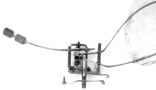
Most of the innovations in vane gears came from the West Coast, and below we see the next step in evolution, called a “California Vane.”
In this gear, the frame ④, which was also called the “Seattle Bar,” is a friction fit on the vertical tube rising from the auxiliary tiller ②. Moving it relative to ② sets the vane. The hasp ⑤, when swung toward the tube of ②, engages the beating stops bolted into the slots marked “3/8” in the drawing of ②. When the hasp is swung down on a beat, the vane can be flipped back and forth rapidly and accurately between the stops as in the previous design. When the hasp is raised to the position shown in the drawing, the vane can be set to any angle relative to the auxiliary tiller. In addition, the vane arms ⑥ can be adjusted to set the amount of leverage the vane exerts on the gear. This design, also known as the “Thorsen Vane,” ruled the waves until “self-tacking” came in, and was used by skiff sailors to the very end.
The “self-tacking” vane gear was invented by Dr. Ted Houk of Seattle in 1939. The first version was a California vane with two adjustable arms that engaged the tiller on a beat. This design was discarded because of a tendency to lock up and cause the boat to sail in a circle. Houk then invented the “break back” gear, in which a simple linkage was used to flip the vane over to the opposite tack. This mechanism greatly reduced the tendency of vane boats to “go in irons.” As the boat headed into the wind, the vane would “self-tack” onto the opposite tack and keep sailing. Later improvements involved a “guying rubber,” which helped flip the vane over when the boat stopped heeling, and the “Liverpool boy,” which held the jib on the old tack until it backwinded, thereby pushing the bow over more smartly.
In addition, “self-tacking” took advantage of the way the racing rules were written. If a boat was working upwind it could be tacked without stopping by a push from the skipper — usually by a pole. If the boat was off course running with the wind or reaching across it, it had to be stopped completely, retrimmed, and restarted. The “self-tacking” feature of the vane enable the vane to flip over onto the opposite tack as a result of the boat being redirected by its skipper’s pole. This advantage was magnified by the the fact that a win on an upwind leg was worth 1 1/2 times a win when running before the wind.
Setting the Vane Gear
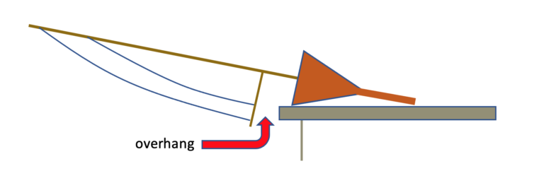
Setting vane gears required great skill and a thorough familiarity with the characteristics of the boat. Despite this, many traditionalists derided the gear because it compensated for lack of balance in the hull design. They were particularly infuriated by the advent of the sliding rig, in which the whole sail plan was moved fore and aft to compensate for different strengths of wind. The picture below is the earliest diagram we have of a sliding rig, from Gus Lassel’s M Class Gurgles of the late 1930s.
The “sychronous sheeting” allowed the main and jib sheets to be moved with a single adjustment; later on, the adjusting bowser was moved to the mas t so the skipper didn’t have to kneel to trim the sails. The boat was before the time of the self-tacking vane; in the Model Craftsman article describing the rig, Lassel noted that an automatic tacking device was the next challenge for vane designers.
Fuller details on setting vane gears can be found in our reprint of “Theoretical Vane Setting” by Paul Fiske. The fittings on the self-tacking gear which refer the “gye” deal with an additional feature of these gears. The vane was set to head the boat progressively more into the wind. At one point the wind pressure on the vane became less than the “gyeing” rubber band and the boat was automatically flipped over onto the opposite tack. This enabled a boat to tack once in the middle of a pond, which could be quite an advantage on the last short tack of an upwind beat.

Vane gears are a complex but rewarding topic of study, especially for lovers of clockwork and other “tricky little widgets.” If you really get stuck, it helps to make a mockup out of cardboard or plastic sheet.
Free-Sailing and Radio Control
Free-sailing boats differ from Radio Control ones in significant ways. They tend to be heavier because they have to sustain some fairly rigorous collisions with pond walls and other obstacles. They are generally of lesser draft, because they have to be able to sail anywhere in a pond.
Also, the vast majority of free-sailing races were match races of two boats at a time, to minimize the number of fouls. This form of racing made for a relatively slow moving day, and limited the number of boats that could be accomodated in a weekend event. Radio control permits races much like full scale practice, with the excitement of many boats jockeying for position at the start and at the marks.
Finally, the great advantage of Radio Control is that you can sail a boat from just one shore of a pond. Venues for free sailing must be accessible all around the water. As the special-purpose ponds that were built by the W.P.A. in the 1930s were filled in or fell into disuse, R/C sailing became more and more attractive.