- Lady Betty ,Part Ill. By Shipwright. Describes how to make fittings for this 36-in restricted class yacht.

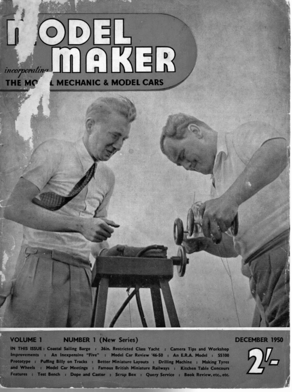
December 1950 “LADY BETTY” Part Ill describes How to Make Fittings for this 36 in. Restricted Class Yacht BY at 2/- lishers. Dyeline full – size drawing of hull, profiles, body plan and half – breadth plan also available price 7/6 from the publishers. This illustration shows completed yacht ”Lady Betty’ with spinnaker set and all _ sails “sheeted home” — not in the correct running position. ODEL yacht fittings are called upon to bear considerable strain and if anything gives way it is always during an important event. For this reason I advocate that all such fittings be silver soldered. The average novice seems to fight shy of this method of joining metals. There is no reason for this as silver soldering is as easy as soft soldering and far more satisfactory in use. If a few simple rules are followed, as set out below, the tyro need not hesitat e to commence operations. The tools and materials are few: — GAS BLOW TORCH.—I can thoroughly recom- ee mend the torch marketed by The Target Manufa ctur- ing Co. of Wollaston, near Wellingborough, North- ants, which I have used for all my silver solderin g work with complete success. Its price is 3/6. The solder used is “Easyflo” made by Johnson Matthey Ltd., of 78 Hatton Garden, London, E.C.1. It is obtainable in either wire or strip. You will require a common brick and some pieces of asbestos; a broken gas element in small pieces arranged excellent. around the job to conserve the heat is To prevent oxidation of the cleaned parts make up a “pickle” by diluting 1 oz. of sulphuric acid with 20 parts of water in a 2 Ib. jam jar. The modus operandi is as follows: — Polish the brass parts to’ be joined with “blue back” emery cloth, clamp together, heat slightly and drop in the pickle for a few minutes. Take the job to prevent hammer marks and bruising. Thick metal should be annealed, ie. softened by heating to a dull red. Quench for copper; allow to cool and then quench for brass. Always polish the job after fabricating to ensure a good finish for the chromium plating. Do not forget to let the plates have all fixing screws 70 as to match the finished job. JIB RACK. Fig. 11—Make a of 20 brass. and shown solder gauge Mark off drill as and silver a foot at pO FS] ©; O27 OO TOT oe _— ° END view “= hae FIG. I. JIB_RACK. either end. MAST TUBE & SLIDE. Fig. 12—The slide is of 24 s.w.g. brass sheet. A piece of 4 in. inside diamete r brass tube will be required, a hole to accommodate the outside diameter drilled in the plate (a garage . available each from the pub- a construction see with of the Hull: Part II covers Mast and Booms. Copies are out of the pickle with a wire hook, and mix the flux into a paste with water, smearing this over the joint. Arrange in the “frog” (the hollow part) of the brick with the pieces of asbestos around it with pieces of the solder wire on the join. Now heat slowly. When the flux fuses turn on full heat and the solder will suddenly run. Keep the torch on for a few seconds to ensure that the solder has run well into the joint. Turn off the heat, allow to cool slightly and drop in the pickle again. When cold wire brush the parts to remove surplus fused flux. There is only one finish for model yacht fittings— chromium plating—it makes the job look professional; brass fittings savour too much of the toy shop model, which our boat most definitely is not. MATERIALS FOR’ FITTINGS.—Brass rod, strip, tube, etc., etc., may be obtained from: — Clay Bros. & Co., 247A Hammersmith Road, London, W.6. H. Rollett & Co. Ltd., 32/36 Rosebery Avenue, London, E.C.1. who will supply the small quantities required. MARKING OUT.—Every job must be accurately marked out for cutting or drilling. You will require a steel square, 2 in. or 3 in. will do, a scriber, a centre punch and a pair of dividers. To drill a row of holes first scribe a line, set off the centre distance between holes, pop mark with the centre punch and drill to the requisite size. To bend, mark off the bending line and gently tap over using a piece of mild steel as an anvil. Interpose a piece of hard wood between hammer and metal ——— II ee ee and oar % Parts I of this series appeared in The Model Mechanic dated August, 1950, and Sept. | Oct., 1950. Part I deals “‘SHIPWRIGHT’’
MODEL MAKER | é) ° 565 oles .| seks Be oo eek hf UJ 278° G , HLL =| oir VAN t © DECK PULLEYS & PLATES. Fig. 13.—Although a drawing of pulleys for the steering given their lines is FIG.13._ DECK PULLEY & manufacture is beyond DECK PLATE. the capabilities of most beginners. The plates are easy to make from 24 s.w.g. brass, but the pulleys should be purchased from either of the following firms :— Bassett-Lowke Ltd., St. Andrew St., Northampton. Lance & Mullett, 16 Meeting House Lane, Brighton, Sussex. C.SNK. HOLES for ® | Neo Woon screws,| © — FIG.12. MAST SLIDE «| & |” PLATE. will do this for you as not many amateurs possess a drill of this size) and the tube soldered in. See that it is flush on the under side otherwise the slide will bind on the plate. Mark off and drill the deck plate in 24 s.w.g. brass as shown. Countersink. the holes for the four holding down screws so that their heads are flush to allow the slide to move easily. Carefully mark off and drill the ;°; in. pin holes, noting that they are offset to give finer adjustment. The pin is bent up from 20 s.w.g. wire. This will give rather a slack fit. A more precision like job would be to drill the plate with a No. 55 drill in place of the ,; in. and make the pin of 18 s.w.g. wire. If the constructor has to purchase a drill I certainly recommend the latter method. Anneal the deck plate to facilitate bending the edges. Another fitting which should be purchased is the turn-buckle. Four are required and they call for left and right hand taps. It is unlikely that such taps will be kit found in the average the FIG.21. SHROUD FITTINGS. of and_ tools, purchase of these items for one job would outweigh the cost of the finished turnbuckle. Fig. 21 shows a i type in common use. STEERING QUADRANT.—This is shown fully dimensioned on the lines plan, a perpective sketch is also given of the assembled job in Fig. 14. Use 20 s.w.g. brass for the quadrant. Mark off, cut out, using an abrafile; drill for quadrant hooks, drill a + in. hole and silver solder in a piece of brass tube from which the rudder tube is made. This should project + in. above the quadrant and }; in. below, and is drilled 6 B.A. clearance. Drill and open out Bh. with a rat-tail file rubthe for the slot ber cord in the tail, FIG.6. and bend down at as angles right MAST HEEL & STEP MAST HEEL & STEP. Fig. 6.—Below deck level the butt of the mast is tapered slightly so as to fit inside a piece of 7% in. diameter brass tube 4 in. long. Fit the mast inside this tube tightly then drill a 7 in. hole in the position shown. Cut a slot } in. deep and + in. wide through tube and mast and fit a piece of +, in. wire to act as a stop which will engage with the slots cut in the mast step. THE MAST STEP.—This is made from a piece of 5 in. square brass. Cut the steps at the end and drill for No. 1 x ? in. brass screws To form the slots for the stop drill a series of holes on the side face and cut down into them from the top face. Clean up the slots and polish off all burrs. HOLE FOR ELASTIC shown. RUDDER, POST The & TUBE. rudder tube is long enough to extend from the bottom of the skeg to 4 in. above the deck. BeHEEL low the hull it °s cut away and the out skeg routed rat-tail EIG.14 QUADRANT & RUDDER a with file 40 to. accom- ASSEMBLY. tte, eoooeoooooo°o eae a 33. The location of this step is important as it must be central with the fore and aft line and directly under the slot cut in the deck for the mast slide otherwise the mast will not be upright. When the positioning is correct, screw down to the bottom of the hull with the ? in. screws.
December 1950 water tight joint. Arrange a deck beam so that the tube can rest against it, and secure the tube by means of a Ushaped clip screwed to the beam. The rudder post is a piece of tube which is an easy fit inside the rudder tube. Blank off both ends with a brass plug sweated in. Drill the lower one with a 7% in. clearance drill for the pintle bearing. The hole must be short enough to allow the pintle of 16 gauge wire to bear on the top of the hole. The rudder must swing as friction free as possible, and must not bear on the pintle plate. Drill and tap the upper plug 6 B.A. so that the quadrant is fixed to the stock by means of the bolt passing through both post and tube on the quadrant. RUDDER BLADE.—This is of mahogany. The back edge must be the same width as the skeg, tapering to + in. at the after edge. Hollow out the back to fit the rudder post and attach the blade to the post with brass screws filing the countersunk heads to conform to the curve of the post. (See detail on plan.) THE PINTLE PLATE of 16 s.w.g. sheet.—Recess the bottom of the skeg to take this plate and silver solder a piece of 16 gauge wire to form the pintle bearing. Two No. 1 # in. brass screws will secure the plate to the bottom of the skeg. I cannot stress too strongly the importance of free, but not sloppy, fit of the whole rudder assembly as the performance of the boat under sail is dependent upon the return of the rudder to the central position Measure length of +4 in. wire required for bars, slip on traveller, bend wire at right angles as shown and silver solder to the feet of 20 s.w.g. brass. These are drilled to take No. 1 # in. brass screws. EYE GUNWALE BOLTS. Fig. 16.—These are made from 20 s.w.g. brass plate and small screw eyes. Drill for shank of eye. Silver solder and cut off shank. File smooth and clean 6% 5 ot, [39° FIG. 15. 2. EYE PLATE SHEET OR SAIL HOOK. _—s LL SPINNAKER SHEET HOOK. DOUBLE HOOK. up. This figure also des- cribes the spinnaker hook FIG.16. HOOKS & PLATES. and various sail and boom hooks. These are made from 20 s.w.g. wire and need no further description. Attach to gunwale with No. 1 # in. screws. — The MAST BAND & GOOSE-NECK. Fig. 7. lower mast band is a piece of 4 in. inside diameter brass tube as used for the mast tube. Silver solder a screw-eye to the after side for the kicking strap, but drill the sides for similar screw eyes. These are screwed in after the band is in place on the mast to keep it in position. These loose eyes and all sheet hooks are chromium plated along with the rest of the fittings. – The goose neck is bent up from 24 s.w.g. brass sheet, the tongue drilled for 6 B.A. clamping bolt and nut. The hook is 7, in. brass wire silver soldered in place as shown. wl at all times. (— x le = o} Lipa modate the curve of the tube; three No. 1 brass screws 4 in. long well countersunk and filed flush, will secure it to the skeg. A rectangular plate, or palm piece, is soft soldered to the tube at such a position as to lie on the floor of the hull to which it is secured by four brass screws, using white lead to form a AO 6 BA NUT & BOLT. 16 S.w.G. ©4 i [hw pe — “ 5″ S— maaveuen Cf FIG.7, ai 76] FORE HORSE (é’tonc). | MAIN HORSE (4”tonc), FORE & MAIN SHEET HORSES. Fig. 15.—The bars are of 16 s.w.g. brass wire and the feet of 20 s.w.g. brass plate. The fore horse is 5 in. long and the main horse 4 in. long, other dimensions as shown. Each is fitted with a traveller and this must be made first. Use 24 s.w.g. brass, annealed, for the body. A small bobbin or pulley is turned to run on the 16 MAST TUBE. GOOSE NECK & MAST BAND. SPAR FITTINGS. JIB CLUB FITTINGS.—The conical ferrule at the outboard end of the jib club is made of 24 gauge brass with a lap joint. The illustration (Fig. 17), shows the marking out form and dimensions and also the finished job. The end and upper eye should be silver soldered in place, but the lower eye can be | the screwed into s.w.g. wire bar. This can be done by chucking a piece of 4 in. brass rod in the hand drill. Clamp the drill “su” club and will thus in the vice and cut the grove with a rat-tail file. Make latter the prevent two, drill for 20 gauge wire axle. Rivet ends of axle. from turning. The Silver solder two eyebolts on top and clean up. Small wood should be screw eyes as sold by model shops are used for all (Continued on page 58) FIG.I7. CONICAL FERRULE eyebolts. WOODEN MANDREL USED TO FORM CONE “oe Fee” eee EB T FOR JIB GLUB. |
MODEL MAKER “LADY BETTY” — (Continued from page 28) RING FOR — STEERING LINES. RAP KICKING etSTRAP 6 ” === TONGUE SECTION FIG.22. WOODEN SPREADER. FOR RING AG. 19. DETAIL“at MAST END OF MAIN BOOM. L_ SAIL REINFORCEMENT. 2. JACK LINE. 3.CLEW EYELET & HOOK. FIG. 18. 4. JACK LINE ANCHORAGE. DETAIL OF 5 _CLEW OUT=HAUL. JIB AT HEAD & FOOT. 6. EYE FOR BEATING GYE. 7. BOOM END CAP. 6. BEATING SHEET BOWSER. BEATING SHEET. 10 DOUBLE HOOK. TO MAIN HORSE G END VIEW OF CAP. JIB RACK. JIB SHEET FIG. 20. DETAIL AT END OF MAIN BOOM. (NOTE CORRECT WAY OF REEVING BOWSERS) tapered to fit into the ferrule. At the inboard end is a + in. length of 4 in. inside.diameter tube drilled to take a screw-eye at top and bottom. There is also fitting. NOTES ON FITTINGS.—The fittings illustrated in this article comprise a full equipment for a small racing yacht. Some constructors may wish to simplify the work upon these items, and there is no reason why certain omissions or modifications should not be carried out. another screw eye fitted to the. side of the club for the jib outhaul. This outhaul consists of a cord passing through the top eye with a hook on the end to engage with an eyelet let into the clew of the sail. This is adjusted by means of a flat bowser. The other end. of the line being reeved through the side eye. Fig. 18 shows the method of reeving the tack and WIRE SHROUDS, STAYS & TURNBUCKLES. —These may safely be replaced by good quality silk fishing line of about 10 Ib. breaking strain adjusted by means of flat bowsers. forestay. JUMPER STRUT & STAY.—There is really no need for this on a boat as small as our 36 in. model, it is merely an added refinement. If the fitting is discarded a back-stay from masthead to transom adjusted by means of a flat bowser must be fitted in its place to take the strain of the pull of the main sail. SPREADER.—This is an essential fitting but need not be of metal if the constructor feels that the form in which it is drawn is beyond his capabilities. The alternative is one of wood (Fig. 22), and there is a certain saving in weight if the wooden spreader is adopted which is all to the good. A piece of $ in. mahogany 6 in. long x $ in. wide will be required. A 4 in. hole is drilled off centre MAIN-BOOM END. Figs. 19 and 20.—The illustrations show the complete assembly at the inner and outer ends of the main boom. A collar of+ in. diameter brassis required to which is fitted four “eyes. The upper and lower ones are silver soldered to the collar, but the side ones are screwed through into the boom to hold the collar in position. These side eyes are for the beating gye. The upper eye has the clew outhaul reeved through it, and the lower one is for the eyed hook for the beating sheet and steering line jack stay. SHROUD PLATES. Fig 21.—A pair of these plates will be required and they are screwed to the sides of the hull and gunwale 1 in. abaft the mast. They are made from a piece of 24 gauge brass sheet with the top bent over to form a lip at right angles to the sides for securing to the gunwale. When fitting these plates or gunwale eyes the mahogany covering board must be cut away to allow them to fit down on to the deck. Shroud plates are screwed to the hull sides with No. 1 x % in. countersunk screws to make a flush leaving ; in. of wood in front which means that the hole breaks through the after side. Thisis quite usual with wooden spreaders. Drill the ends for the stays and reinforce by pressing in two small sail eyelets. Now curve all sharp edges to form an oval section and varnish. Drill all holes before shaping. To attach to the mast bind tightly with white carpet thread and varnish over the binding. 58


