- National Marbleheads at Hove.
- Simplicity in a Vane From The West. By J. Weeks.
- Vane Gear and It’s Effect on Trim. By H.B. Tucker.

NOVEMBER 1955
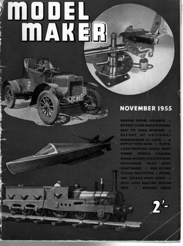
Dh ee e 4 a: MAKER Heading shows Bill Grint in typical National Marbleheads at posi- tion with Foxtrot Adjoining is L. Wareham’s famous Doris H Hove AN entry of forty-two boats, with forty-one actually at the start, including three from France, made this year’s National Marblehead Championships at Hove the most closely contended yet. Such an entry undoubtedly caught the M.Y.A. by surprise, for an additional day of sailing allotted would have made everybody’s task much easier, though not to say more enjoyable. However, it goes a long way to balancing the disappointment that the 36-in. Class entry did not fill, earlier in the season. | In an event where skilful sailing more perhaps than the actual yacht decided the day, it was good to see a young though seasoned skipper in the shape of W. Grint of Norwich take the trophy. Bill Grint has been a regular entrant for years, either as skipper or mate, sharing Charlie Adams’ 1953 victory in the latter capacity, and coming third in 1952 on his own account with his yacht Tango. The tempo has now changed to strict dance rhythm with his 1955 boat Foxtrot, which certainly waltzed away with the final by a lead of four points over local expert D. Bateup’s Cherie II. Hove Lagoon once again demonstrated the pitfalls awaiting an inland sailor making perhaps only an occasional visit to the stronger airs of the seaside. This was particularly noticeable in the French contingent, who normally sail on a canallike inland water of limited size much sheltered from strong winds. They enjoyed their visit immensely and hope to return with added experience next year—and in assessing their efforts we should remember that only ten M class yachts are registered as yet in France, and this was their very first effort to compete in a National event. Left: J. Voigner of Reims Club, France with Babel III. 616
NOVEMBER, 1955 J. Meir looks grim as he maaiches Hopalong against the winner ‘oxtrot Equally important in this fine summer was the number of new boats that had not been fully tried out before tke event. Hop-a-long, an Emma Duck design sailed by J. Meir, was a case in point, though even so it did well enough to reach the final, and hold its own very fairly. Guy Blogg’s Manatee was another interesting newcomer, employimg its skipper-designer’s Circular Arc methods. Again, unfortunately, its skipper had not had enough time on the water to be able to provide a true comparison against conventionally-designed craft—but our thought is that next year it will be extremely formidable. That old faithful Doris H, which won in 1954 in the hands of L. Wareham, again proved a danger throughout, winning Division B, and always proving that a good skipper very nearly makes a good boat. We liked the two new “Little” boats from A. W. Littlejohn’s board, Little Hurry, skippered F. G. Ivory, and Little Haste, in the designer’s own hands. This latter boat very nearly made the final, coming fourth in its division. N. D. Hatfield put up a good show under the Southend club’s burgee with his Troll, though we are more accustomed to see him with a Y.M.6m. O.A. flag flying. B. Dale with his Triumph had to sail off the tie for third place in the final against Doris H, so that all along it was a ding-dong struggle. Our consulting editor on yachts, H. B. Tucker, remarked on the grand efforts on the part of leading skippers, and considered that much of Bill Grint’s success in the weather boards was due to Charlie Adams’ crafty advice to put on an iron hard Liverpool Boy—so that Foxtrot kept going all the time, when other boats were screwing up. Mr. Tucker has also developed strong views on the mixed blessings of terylene sails and vane gears in general. The latter subject he covers on another page in this issue, and will be dealing with the question of sail materials in the near future. The French boats were interesting in that they showed how difficult conditions must be in France today, with very little help from their model trade in the way of fittings, as all these had been made by the entrants. Lack of any good facilities to exchange advice must also be a handicap, for with a month or two amongst British clubmen they would certainly abandon some of their building methods which spell trouble, as, for example, the veneered deck of one boat which seemed anything but water tight. A. W. Littlejohn’s latest Little Haste going well against Foxtrot 617 Mr Jennings reports that he has received very friendly letters from the Federation Francaise du Yachting a Voile, thanking the M.Y.A. for the welcome extended to their first M Class team, and a personal note from their principal skipper Mons. R. Cheret on tehalf of himself and compatriots.
Left: N. D. Hatfield, who came fifth with Troll commences a board against Denson skipper F. H. Fiztjohn with Anemone Above: Local expert, D. Bateup of Hove and Brighton with Cherie II and Guy Blogg’s interesting Manatee in the background saying how much they enjoyed their visit and congratulating the organisers on their very high standard. We do indeed hope this is but the forerunner of regular continental participation, and, equally important, visits from our own “yachting ambassadors” to French and other continental waters. We would again emphasise that Model Maker has this matter very close to its heart, and will encourage such activity in the most practical manner. As usual the club arranged a pleasant Saturday evening dinner for competitors, with that very good friend of local model yachting, the Mayor of Hove, in the chair. O. O. D. Jennings, in between editing the M.Y.A. News, and running the meeting, found time to prepare a speech of welcome in French which added to the enjoyment of the evening, when the French entrants were presented with souvenirs of their visit. Verdict on the meeting must be that Marbleheads are now running the A-Class boats very close in the matter of racing popularity, and hopes for the future must be fixed on a full scale weeklong regatta for them next year. BRITISH OPEN M-CLASS CHAMPIONSHIP 1955 FINAL DIVISION I. 2. 3. 791 571 482 6. 925 8. 9. 10. 4. 7. 12, 13. 14. 15. 16. 675 713 378 W.L.Grint … 927 17 4th L.Wareham D. Bateup ae ON 13 5th WN. D. Hatfield 3rd =~-B. Dale… . = 482. 12 6th J. Meir … A Cherie Il Troll Triumph Lorelei Gavotte Phildrake DIVISION D. Bateup N. D. Hatfield B. Dale W. Jupp T. Harris Hove & Brighton 95 Southend 73 Dovercourt 69 Y.M.6m.O.A. Y.M.6m.0.A. G. Holland-Jones Gosport 63 495 746 631 J.C. Liddle Jemima Duck J. Finlayson Manatee G. Blogg Comet P..T. Mustill Poole South London Nth. Liverpool 6! 58 56 934 931 761 935 Little Hurry Ichabod Bombay Duck Luvaduck F. G. Ivory H.E. Quennell V. Crean J. Palin M.Y.S.A. Clapham Guildford Birkenhead Hastings 56 554 Sik 50 49 498 Anemone 912 Zoe 691 748 19. 20. 892 680 F8 Marguerite Tosca Blue Mist Emma Babel III G. Adams Southgate 62 F. H. Fitzjohn Danson 47 A. Penn Birmingham 46 J. Voigner Reims P. Ratchelous A. K. Smith F. Day Hastings Bristol Danson Uncompleted resails in the divisional sailing were divided. I. 64 64 Skuall 17. 21. Ist 2nd 927 932 904 .511 6. 7. 893 718 9. 10. 762 774 8. Il. 12. 13. 46 45 33 ll 224 2. 3. 4. 5. 781 645 467 … Sst 224 571 2 12 i 10 B Doris H. L. Wareham London W. L. Grint J. Meir A.W. Littlejohn A. Turner Cresta ll Alexia J. E. Weeks J. Watts Red Witch Rob J. Deacon G. Cobb Clapham Poole Cc. M. Smith D. Harrison Y.M.6m.0.A. 56 Hove & Brighton 544 Junelll Avocet Jay K. E. Roberts Norwich Birmingham M.Y.S.A. Hove & Brighton Bristol Danson Birkenhead 704 68 63 61k 58 14, 15. 922 876 Senlac lV M. Holt Cc. Blundell H. Death Nth. Liverpool Southgate 48 464 16. 17. 18. 19. 20. 888 370 684 F7 FIO May li Aphrodite Carol ll Babel ll Caprice D. Barber J. S. Thomas G, Loveless R. Cheret J. Prin Southgate Bristol Ryde Reims Reims 46 44 35 264 233 Estro Scottie Hastings 86 774 724 72 583 The tie for 3rd place in the final was decided by sailing-off. 618 87 Foxtrot Hop-a-long Little Haste Isa 54
J. WEEKS INTRODUCES A’ SIMPLE BUT STURDY VANE GEAR SIMPLICITY IN A VANE i FROM THE WEST WE have read with great interest, no doubt, of how to use the vane steering on all points of sailing and I dare say most skippers have their own pet theories and ideas, but we have yet to read of a “simple” vane steering gear. By “‘simple” vane I mean one which can be produced by the average model yachtsman without an elaborate workshop, yet is perfectly balanced and will do all that is required without gears or complicated linkages. During the ““M” Class Open Championship at Hove this year I noticed there were several vanes being used with huge gears of up to 2 in. diameter, this being the linkage between vane and rudder, the total weight of vane and linkage must have been in the region of 7 oz. Apart from the fact that they are unsightly, are these gears really necessary when a normal type slot and pin linkage will do all that is required if properly adjusted ? The vane steering I have designed after a great deal of experimental work with the various types of Fisher, Lassel and Ballantyne is, as you will see from the drawing, very simple. There is no linkage between the feather and the counterweight when it is set for self tacking, except through the “tacking” stops or “guying” spring on the feather rack. When in the running or reaching position the feather is held in the central position by a split pin, for beating to windward, using the self tacking device, the vane is set in the central position, the pin removed and stops adjusted to give the desired amount of helm, usually the feather is set at about 30 degrees off the centre line. For guying the spring tension is adjusted on the feather rack as shown in the drawing, and used in conjunction with a normal “boom” elastic guy and rudder stops will give long or short guys perfectly. The feather, as will also be seen from the drawing has a stabiliser on the trailing edge; this is not my idea, but I have proved that by using this form of feather one is able to cut down the total area of the feather by as much as 25 per cent. without loss of efficiency. It is also much more sensitive in light airs and feather “flutter” is negligible compared with the ordinary type of feather. The vane is extremely well balanced. As will be seen there are two balance weights; the small one balancing the vane disc, linkage pin and arm, and the large one balancing the feather and tacking device, etc., both units being balanced separately before assembly. It is also essential that the rudder and linkage arm must be balanced, and this must be done with the rudder immersed in water or the balance will be upset by the flotation of the rudder. For those interested in making linkages and pintles it should be remembered that stainless steel cycle spokes and mudguard stays are excellent. The drawing is almost self-explanatory, and provides very little constructional difficulty. It stood up well under stern conditions at Hove which speaks for itself. It is most important that all soldering is silver soldered, not only from a strength point of view, but also because, if sailed on the many salt water lakes available to model 626
NOVEMBER, yachtsmen, the sea water will swiftly attack a soft solder joint. For a pleasing final appearance it is worthwhile to get “‘the little man round the corner” to chromium plate the work, or, if a matt finish is preferred, it can be cadmium plated. Should any parts be beyond the workshop facilities of readers Model Maker would be happy to put them in touch with a small engineering business which can do as much or as little as they require quickly and skilfully. Those who are at all dubious of their skill in balancing and adjusting a vane gear of their own construction are referred to articles on this subject by A. Wilcock which have appeared from time to time over the past two years in Model Maker. Many vanes of sundry patterns have been made by readers and we shall always be pleased to answer constructional queries on the subject; or to refer points on sailing with these gears to expert sailing skippers. SIMPLE VANE GEAR 1.750 R. COPYRIGHT OF MODEL MAKER 38. CLARENDON PLANS RD, | ! Pear | SERVICE WATFORD, a 600! i HERTS 300 || 3-00 | &WASHER r, Pe HeTUBING So. ay TSS } a Gude , J. Utes 1500″ f 2 BA: Bi : 1955 250° ; al SS = x ‘4sfice – Rice : ; -—— e . Leg Aste ~ aos | ‘ 2-400″ 1400 IA. +(M. CLASS) LOCKING PIN 6 TUBING BALANCE WEIGHT SELF FEATHER TACKING STOPS QUADRANT STOP (CYCLE SPOKE » FEATHER RACK . COMP. 20 GAUGE === “= & ARM a eS | & Out —— – a ) $T.S) SPRING SOR lo = fo re 5 lo 6 STABILISER { | 8 8A y b | DISC t PB) \ VANE —— SPECIFICATION CSK SCREW Ae BRASS ROD “@ DIA. FOR PINTLES & BALANCE 1:00″ WEIGHT EXTENSION. = i, LOCKING PIN HOL oe FEATHER PINTLE (sts) V4 BRASS TUBING ST. STEEL CYCLE SPOKE FOR VANE BODY. FOR STOPS & LOCKING % srass TUBING FOR FEATHER BODY & MAIN . PIN. PINTLE BODY. 8 BA. CSK. SCREWS 4 OFF. 8 BA. NUTS 4 OFF. 6 BA. SCREWS BRASS oo —— = = i HOLE swaceD out 4 ‘To /4 DIA. HOLE WEIGHT ALL 4 2 OFF. 6 BA & 6 BA. O7zS. JOINTS TO BE SILVER SOLDERED. SH} -| 656 Se a MOCKING PIN WASHERS loj——— 250 MM, 398 627
NOVEMBER, 1955 ‘THE designer of a model yacht has not only to draw the lines of the boat and calcul ate her displacement, but he has also to prepare a Table of Weights for the builder to work to. Here, for instance, is a Table of Weigh ts for an A-class yacht displacing 57 Ib.: 57 NNNKA 43 347 Trimming Ballast Lead Keel ane o DORADOOCOOR Sundries lb. o Hull (including Deadwood) … AS Deck (including Beams and Hatch). .. Paint and Varnish …, ae! as Rig (including Spinnaker and Boom) Steering Gear «se Ia eee Fittings VANE GEAR AND ITS EFFECT ON TRIM BY H. B. TUCKER of leverage. On the other hand, a similar weight placed Now, in computing these weight s, the designer must be guided by past experience of the average builder. an equal distance forward of the C.B. would counteract this. Now a Moreover, particularly in a design for publication, he may vessel floating in water displa ces a mass of water having an equal weight to her own weight. Thus our 57-Ib. A-class yacht would displace 57 Ib. of water, The designer, therefore, calcul ates the volume of water displaced by the hull he has drawn (z.e., the volume of the underwater body of his boat). He finds this to be 1,539 cu. in. As the vessel is to be measured in salt water, he divides the volume in cu. in. by 27 which gives him the weight of water displaced (—=57 Ib.). If measurement is in fresh water, as in some of the M.Y.A. classes, he not know what method of buildi ng will be employed and some methods are likely to produc e a lighter hull than others. Similarly, timber varies greatly in weight, and even from plank to plank, when both come from the same tree. Hence the hull can easily be $b. lighter or heavier than the specified 6 lb., but this is sufficient to allow for a good strong hull. In the A-class particularly, as the boats are so heavy, hulls must be strong enough to resist striking the sides of the lake or the impact of collision with another boat of the same weight. In a class divides by 27.7 and if our boat has to be measured in of this size fortunately there is sufficient margin of displacement to provide for a good strong hull. fresh water, her displacement would only be 55 Ib. To find the centre of buoyancy, the designer calculates the centre of gravity of the displa ced volume of water. The method of doing this can be found in any book on Naval Architecture, so need not be detailed here, In order that the yacht may float on her designed The Table of Weights is not a hard and fast thing however. In fact the only thing about it that is hard and fast is the final total of 57 Ib. So the builder must copy out the Table of Weights and pin it to his workshop wall. At each stage of the proceedings he must weigh his boat and should note against each item the actual weight. It is only in the bigger items, like the hull, that there is room for much variation from the scheduled weight. For example, if one could save 25 per cent. of the weight of the fittings it would mean a mere 1} oz. I do not imply that such savings are not worth while, always provided that the fittings are not too light and flimsy for their job. fore-and-aft trim, the centre of gravit y of the vessel must fall in the same vertical line as the C.B. In other words, it must be in the same fore-and-aft position. Since al] we want to know for this purpos e is the fore-and-aft position of the C.B. and C.G., it is unnecessary to calculate the exact height of these points. While the C.B. is easy enough to calculate, the C.G. is more difficult because of the liabili ty of the various weights of the component parts to differ, and also because one also has to know the positio n of the individual C.G. of each component part. Of course, theoretically, if one calculated these individual centres of gravity one could then work out the combined C.G. for the entire boat minus the lead keel, and then arrange the lead keel so that its C.G. correc ted any error in the combined C.G. of the other parts, and brought the C.G, of the whole boat into the same fore-a nd-aft position as the C.B. In practice this is easier said than done, so the only thing the designer can do is to be guided by If it was found that 6 oz. is insufficient to provide fittings adequately strong, it would be better to exceed the prescribed weight by an ounce or two. Often small discrepancies balanc e themselves: an ‘ounce on one item being lost and one gained on another. Final adjustment to the designed weight must be made ‘on the lead keel if other weight s have been exceeded. On the other hand, if the total weight including the lead keel falls short of the total, a little extra inside ballast can be added to make the total correct. Once the hull is built, however, there is not likely to be much variation in the other items, so that the builder ‘can then forma very close estimate of how near his boat will be to the design weight, and see whether any lead will have to be forfeited from the keel, It is always wise ‘to keep 6 or 8 oz. in hand for trimmi ng ballast as this will always enable the builder to adjust matter s if the centre ‘of gravity of his boat is not quite correct. It may be asked why the designer cannot ensure the ‘C.G. always falling exactly in the desired fore-and-aft position. The answer is that woods differ in weight, ‘builders’ methods differ, and scantlings vary. Likewise, the weight of such things as fittings vary. The vane gear, as will be shown later, makes an enormo us difference ‘to the fore-and-aft trim, and if this weighs even an ounce extra it will affect the yacht’s trim material ly. The reason is, of course, that being so far aft it exercis es a great deal experience, but it is very desira ble to provide a margin for contingencies. The internal trimmi ng ballast does this, and 8 oz. is such a small propor tion of the total ballast that one can ignore the slight difference made by putting it inside the yacht instead of on her keel. In the days when Braine steerin g was universal, experience showed that one weight counterbalanced another, and it was quite safe to put the C.G. of the lead keel directly under the C.B. But with the vane gear matters are very different owing to the leverage of this extra weight so far aft. Let us see how this works out for our A-class boat. The total weight is 57 lb., of which the lead keel weighs 43 lb. 80z.: The vane gear weighs 6 oz. and the remainder of her 13 Ib. 2 oz. We can assume that the C.G. of the remainder (13 Ib. 2 oz.) falls in the same fore-and- 635 (Continued on page 650)
i H Dear Sir, Is this a Record ? Dear Sir, I have been a staunch I have been reading ‘““MopEL Maker” for just over a year now, and I feel I must write and congratulate you reader of your magazine for some time now, my main interest being model on publishing such a fine magazine. I find my greatest difficulty in model boat building is deciding on the right motor and propeller for my hull, cars. I thought one of my experiments with the making of model car bodies might help starting in the model car line. so I would support Mr. D. S. Jones’ pleas for a table giving such sizes. Finally, I would like to say thank you to Peter Holland for his space models—they’ve given me plenty of amusement. Take an Yours faithfully, G. S. SHEPPARD. VANE GEAR & EFFECT ON TRIM Carlisle. point. Where should the C.G. of the lead keel be placed so that the C.G. of the whole boat falls at the same position as the C.B.? As the 13 Ib. 2 oz. has its C.G. in the correct spot, we are solely concerned with the vane gear and the lead. The method of ascertaining this is by taking moments about the C.B. Our vane weighs 6 oz. (—0.375 lb.) and is 31 in. abaft the C.B., so its moment is: , 31x 0.375 inch-pounds=11.625 inch-pounds. This is aft of the C.B. so our lead must be placed a distance ahead of the C.B. where it will exercise a counter influence of 11.625 inch-pounds. Our keel weighs 43.5 pounds, and if it was 1in. forward of C.B. it would exercise 43.5 inch-pounds, but we want 11.625 inch-pounds, and by division we find that the distance the C.G. lead must be ahead of the C.B. is almost exactly 0.27 in. This figure can be taken as approximately right for all A-class yachts, and the small amount of internal trimming ballast discrepancy. will be adequate to adjust any Similar figures can be worked out for the other M.Y.A. Classes from a Table of Weights, or for any individual boat. One point that often puzzles beginners is that the weights of lead castings frequently differ from the designer’s weight. Sometimes a casting comes out light, but more often it is appreciably heavier than intended. There are a number of points that may influence this. Lead is not always absolutely pure. Pure lead weighs 6.33 oz. per cu. in., but sometimes is as low as 6.2 oz. Occasionally there are concealed blowholes in castings, and naturally these reduce the weight. So much so that one designer told me that two keels cast from the same pattern differed by nearly 2 Ib. in weight! On the other twelve-inch gramophone record, cut G. ROBLEY box to make his sand mould. The sand is then ‘‘tamped’ down hard, and the pattern removed. To ensure the pattern comes clean out of the mould, the moulder moves it very slightly, and naturally this tends to enlarge the mould. After the pattern is removed, the inside of the mould is smoothed over to ensure a clean casting, and this again tends to enlarge the mould. The usual result is that the casting comes out somewhat over-weight. This is, of course, better than being under-weight, as one can soon put this right. However, all the designer can do is to calculate his lead keel carefully, while the builder can make his pattern absolutely correct to drawing, but this is no guarantee that the lead will cast exact to designed weight. Hence designers often draw their keel to cast a small amount of over-weight, and leave the builder to adjust matters finally. Before closing this article, I should like to saya little about the application of this system to classes other than the A-class. In the case of the 10-Rater we have a boat of approximately equal length to the A-class, but much lighter. Hence the lead keel to counterbalance the vane is lighter, and needs to have its C.G. still more forward of the C.B. This may not be convenient without altering the design of the fin by steepening its leading edge, and that may not be altogether expedient for other reasons. The answer to this is to fix a few ounces of inside ballast, say 3 oz., the same distance forward of the C.B. as the vane is aft of this point. We then have merely to consider the vane as weighing 3 oz. instead of 6 oz. and our C.G, lead will remain at about 0.27 in. ahead of C.B. This small counter-balance weight should be fixed before the deck is put on, as otherwise it is a difficult job. It is apparent from the above that the distance the vane gear is from the C.B. has a great effect on trim, and this is yet One more argument for not placing the rudder too far aft. f hand, the moulder places the pattern in the moulding Christmas Humber December issue, on sale December Ist, will feature: MR. ROBOTHAM—A working model robot that walks, flashes lights, etc.: the most horrific since Frankenstein! CARIBBEE—First instalment of a suver-detailed scale working model of a famous Trans-Atlantic Yawl, employing new building methods and sailing technique. just (Continued from page 635) aft position as the C.B. The vane gear is 31 in. abaft this _ reader into sections and warm until it is workable, then it can be moulded into any shape body required. When joined together forms a serviceable and inexpensive car body. Yours faithfully, Wishing ““MoDEL MAKER” every success in the future. West Wickham. old any WISHBONE SCHOONER—Lines of a semi-scale craft that will appeal to our wide circle of would-be schooner builders. ELECTRIC RAIL TRACK—Working on a new principle described in detail. MODEL SOLDIERS—More on this fascinating subject. CRAMPTON LOCO is completed with typical period coaches. ANOTHER 3D GAME—In response to popular request. MG “A” is subject of our PROTOTYPE PARADE. BOAT RADIO CONTROL continued. All our usual features.


