
At my age, I told myself that was the time to rewind the reel of my life.
I wrote two books, one retracing my life since born and a second one dedicated to my passion of ever the “Sailing Boats”
Fortunately, I met the real Sailing Boats and later the World of Sailing Models.

PS a See ery ee eee ey re ee 7 VRE, Tow _,’ ve op — — SS —ien oo, s A — AU Cn, . : SAR a eS ay ee Cees et aekt ere ert “ye eh Mome ‘ a
Directly published on the Web via Model’s Forums First Edition – December 2019
Preface At my age, I told myself that was the time to rewind the reel of my life. I wrote two books, one retracing my life since born and a second one dedicated to my passion of ever the “Sailing Boats” Fortunately, I met the real Sailing Boats and later the World of Sailing Models. On my road I met a lot of very kind people, but also many stupid ones, they will recognize themselves because having met them ‘here and there’ are not nominated. This book is dedicated to my RC Sail Model friends: The first is Pierre Raynaud, my mentor since the beginning, may rest in peace. and than Flavio Faloci the Architect from Genova Dario Aliprandi (Amon) from Milano Paolo Saccenti (Amon) from Milano Luigi Ferrario from Portovaltravaglia Sergio Saba from Trieste Mauro Folicaldi from Bologna Gianluca Montecchi from Monza Raffaele Galardini from Pisa ‘Grakula’ from Cecina Toni Clemente from Napoli Walter Ottavi from Venezia Tiziano Bressana from Brescia Dario Motta from New Zealand Alan Wymer from New Zealand Gilles Blais from Canada Eric Sponberg the Architect from Florida/World Andrew Stansfield from South Africa Ivor Bittle from England Mark Smith from USA Celtic Spirit from Ireland Dick Lempke from USA Twister from UK Larsli68 from North Europe Thomas Armstrong from Chili Astute Composite from UK/Spain Earl Boebert from USA Bruno Lacaze from France Antoine Fleury from France Pascal Delapierre from France Special thanks to Andrew that assisted me with my Italo-American English ! I do apologize for the “friend names” missing ClaudioD
Index Preface heeececccccecesseneeeeeeeeeeeeeeeeeeeees page Introduction ne Foreword cece cece ccc ce cee ceecencenceusesvenves ” 32 Lesson 1 ieee ccc ceccecceceeceeceuceuceuceucescens ” 36 Lesson 2 cece ccc ccecceceeceuceucenceucescenves ” 38 LessOn 3 ieee cccceccecceceuceuceuceuceuceuceccens ” 43 cece cece ccc ceceeceecencenceusesvenves ” 44 aie c ce cceccecceeccecceuvcusceuscusceuses ” 51 LESSON 6 Lecce cc ceccecceecceeceuvcusceuscesceuses ” 53 Lesson 7 ac ceccecceceeccuceuceucevcevceucesvenves ” 60 Lesson 8 cece cece ees ceceeceucencenceusescenves ” 65 cece ccc ccc cee ceeceucencenceucesvenves ” 68 cece cece cece cence cee ceecensenvenves ” 74 — Lesson 4 — LesSON 5 — LessOnG —_ Lesson LO My Models eee cece cece cece cc ee cnc cencenveuees ” on. eee eee eccce eee e cece eee eeeeeeeenes ” 78 Class Marblehead on. ccc cece ec eee cee ee ees ” 81 ec ccccceccecceuccecceuvcesceuscesveunes ” 125 RG65 Delta Rig …….. ccc eee eeeeeeeeeeeees ” 137 RGO5 Bulb cece cece cece eee e scence venees ” 146 —___ ieee cei cc cece cece ceeccecceeceencenceuees ” 150 —___ iii ccc ccc cecceecceceuccesceevcesveuncs ” 163 id eiccccceccucceuccecceuvcusceuscesceuses ” 194 —__ aie cece cece sees ceecencceeceevcesveuees ” 227 RGO5 CD-CAT AC 120 AC 33 AC 100 Ten Rater – 1OR AZB-90Q ae eee e cece ee ee cece ” 279 iii ccc cceccecceeccecceuccusceevcesceuees ” 299 ” 317
Introduction Who am’ I? Claudio is my name while D. is the initial of my Family name. I’m an old man born in Italy in 1936 before the start of World War II. My hometown is close to Varese, a city in the North of Italy located between various lakes. Some years after the end of the War, we spent a day visiting one of the local lakes. It was the first ttme when I saw a boat moving through the waters without an engine or paddles. Later I discovered that the engine was the Sail and the fuel was the Wind! From that moment my love for Sailing Boats began. Student up to 17 years, being talented in drawing, I was aiming to become a civilian architect, but the life decided differently. My father car spare parts commerce went bankrupt and money at home was scarce. A day, back from school, I saw an advert on the wall that read: ‘Join the Air Force, you will start a new career So on that day I decided to join the Air Force. Became a Radar Specialists, but after 12 years of service I decided to resign from Air Force to join a new adventure with the newly created “European Space Research Organization” I spent 33 years in Applied Research, Development and Management tasks for various Satellites Programs. During these years I traveled around Europe and United States as well in South America during Launch Campaigns. Salary was good and managed to make sufficient economies to buy Sailing Boats, like a Rival 38 bought as a Kit and finished 5 years 5
later with the restoration of a Vintage Dragon and Snipe made with Mahogany wood. a9 Lake, j lseo Lake Garda & Nilano AOMBARDIE Varese and lakes around
Excluding the 60’s in Venice, Leisure and Sport sailing went on for about 25 years. The dreaming image of a Dragon on the Lake of Como
While my brother was waiting his weekly Tex Willer issue, = ( myself I was happy to get my “Sistema A” and “Fare” a sort of popular science magazine. After building small Gliders and Rubber Band Models all ending into the tree branches, I decided to opt for a more durable model activity. I knew that a model shop was at half-way from School and Sea father shop and a day I went \Gnea visiting that Store. The store was the MO-VO in E WS oN Z 2 ®, Santo Spirito Street. After explaining that I was tired of loosing my Airplane Models, they proposed to build one of their products a Sailing Model called “Ninfea” a sort of Star of 80cm length and equipped with a Braine Vane.
I was only 12 years old and walking back home; crossing the Town to save the Tramway ticket money to buy the materials needed as well the Models Magazines. This was my first Sailing Model and rather reluctant to let him free too far and this is why it was attached to a fishing line. Idro 1948 Braine Vane traveler elastic band rudder axis
My first Model in 1948! sy b- oe =~ ‘ haiiieal Sac 71 years ago! 10
In the 1960’s, while in Air Force, I got the opportunity to sail in Venice Laguna with a Snipe. Another friend was instead sailing with a local centerboard boat called 5.50mt, developed in the North of Adriatic Sea. Once resigned from Air Force [ went living in Holland where the sailing is almost the national sport! My boss and I we bought an iron chine sailing yacht used only for inland lakes. During that period it happens to meet many Sailors as well Sailing Ship Yards. The annual HISWA Exhibition in Amsterdam was the event that I could not miss. It was in the 1972 when I met people of the Coniplex Factory famous for the Contest Yacht series. They offer to teach me, during Week Ends, the Glass fiber lamination technique, in turn they asked to reproduce a static model of one of their Yacht production that was the Contest 33 as depicted here in the following pictures. The model was scaled to 1/10 and all interiors were also made including the electrical installation, galley, berths, etc. 11
Contest 33 1972 At the end two models made one was the Contest 33 and the second was the Contest 29 With Werner, my boss, we went sailing for a couple of years in the Holland internal waters, until he decided to buy a Racing Yacht like the Contest 31H. This boat was too expensive for my budget at that time. Only in 1978 I managed to order my first boat, the Rival 38C. It was a sort of Kit where all the interiors where supposed to be built by myself, under those conditions was cheaper then Contest 31H. Rival Company of Southampton supplied all materials needed. In 1979, I was transferred to the city of Toulouse in the South of France where I was supposed to join the Satellite Team of Sirio-2. 12
In that occasion with the help of a couples friends, including Werner, we sailed down the English Channel. One week later we where my Flat Canal du Midi mooring in the Port Sud Marina close to Toulouse along the historical Canal du Midi. This is the Rival 38C. ‘C’ stay per Cutter Rig. This image was taken in the Mediterranean Sea close to city of Sete. The Ermitage was sold 5 years later when Francoise, my wife, decided that she could not overcome the issue of sea sickness. Recent news indicates that the Ermitage is sitting in Barcelona in Spain.
Thinking that Ermitage was going on to a new life, I convinced myself that I could not continue without a sailing boat. The wonderful souvenirs from Venice pushed me to search for a Snipe. During a Holiday break in the Como Lake in 1996 I met people that indicated a Nautical Club where I could eventually find a Snipe Finally, the old vintage Snipe was found and it was really in bad conditions under a pile of automobile tires. Apparently was standing there since the 70’s according to the ship yard. Not discouraged, I went buying a Trailer and soon had the hull in Toulouse. I was unaware of the adventure to come; I decided anyhow to do whatever was needed. I began to search Marine wood suppliers. This was not an easy task so far inland, but eventually succeeded. A ply-wood factory, near the city of Bordeaux, delivered the sheets needed for the Deck restoration. The Stern and centerboard case where both rotten through. The mast was in very poor condition and a new one was needed. Sectioning the mast has found a peculiar thing. One of the pieces had very close growth rings and someone informed me that this was probably a Heart Pine from Siberia. 14
I build up a flat base to assembly a new mast. After 900km drive, the Snipe called “TIVAN” arrived home TIVAN is the name of one of the two dominant Winds on the Como Lake, the one blowing from North in the morning and the other is the BREVA in the opposite direction in the afternoon. 15
Some days later the TIVAN look that way and below a couple of months later almost finished! 16
17
18
19
> = we | Snipe single handed sailing in the Como Lake in 1998 20
Below, in August 1997, while sailing in the Colioure waters in the south of France Some time later the Snipe was retired to the garage since a new adventure was a challenging my mind. I was eventually thinking about the Star, the same boat often seen in the Venice Laguna racing during weekends with the Snipe. Finally the answer came during a holiday break when I was on the Ré Island close to La Rochelle in France. I was reading a Sailing Magazine and happened to come across an advert for a mahogany wooden Dragon of 1963 that was for sale in the Brittany Region. Since it was close, I visited the Yard the following day. The Dragon was apparently standing there since long under a shelter. The funny thing was that the owner had put it up for sale because he 21
was 65 years old like me, that at the contrary, wanted to start sailing with a Dragon, a mythical Sailing Yacht some damages already visibles rust areas and stripes separation home 22
Once at home I started with the total removal of the Deck and replaced by Marine Plywood of 8mm. I managed to build a new Roof and the deck covered with teak stripes of 7×1 cm = 8mm and with Sikaflex for the black joints. sae 23 Nee a l Eres – le ea ae = CP Se le
roiren Keel Wood a oat i = .i ers a A lot of rotten wood needed replacement 24 *
During restoration process with my lovely cat =~ a& my BOSS | 25
ellanesmiaia winch still to be meunted 26
t —e —— | if Efrem STYX-2 pronto per partire sul Lago di Lecco Here after water tests in Port Sud Marina The Dragon, alias Styx-II, was finally ready, having take almost 2 years and about 1870 working hours. Here on the Lecco Lake while waiting for a mooring place in Cannes 27
Being a wooden boat required a lot of maintenance Here after antifouling in Cannes Yachting Club in 2001 Out of some 14 or 15 Dragons, the Styx-II was the only wooden hull. Styx-II was heavier than the fiberglass version. At races, the best placement was in general the third-last, only once it happens to came second at 30cm from the first. Why? Was a windless day and we managed to create our own wind by rolling” the boat and “pumping” the jib as well the rudder. With the team on board being about 350kg heavier than others, the inertia did the rest. During my stay with the YCC- Yachting Club of Cannes, I participated in about 20 races per year including Christmas. We were participating just for the pleasure of sailing since we knew that Styx-II was not a competitive boat. 28
The chance to race lasted for about 4 years when the first asthma crisis appeared at the age of 69. Doctors never found the causes of the allergies, but I suspect the wood dust accumulated by my lungs during restoration. A Vintage Boat Amateur offered to buy the Dragon as well the Snipe that I restored some years before. Here during a pleasure sailing in front of Cannes “la Croisette” 29
In 2003 was necessary to change the Main Boom. All enquiries aiming to Spruce wood ended up with excessive costs. So I managed to find some Red Cedar wood cut to the size I wanted. The Boom consisted in 6 layers according to my design technique. 30
”Nice” place to work ! main boom construction Nice Finishing the Main Boom 3] Feb. 2003 |
The plastic tube was integrated and bonded to allow a smooth sliding of the Main Sail Luff 32
Foreword In previous pages, I did introduce myself where it can be seen that I’m rather enthusiastic about the Sailing World. Going further, I will trace the path that has led me to discover a new aspect of the same World. When I[ was 12 I did not realize how much was complex and fascinating the Science of Sailing. Was just a newly discovered passion as a child while assembling a Sailing Model Kit. This book is not supposed to be a Construction Manual, but a collection of several ideas around my understanding of the RC Sailing Model as compared with the Real Boats. Those persons who are familiar with this hobby will find useful graphs that often are left in the corner. Certainly, the graphs are representing the results obtained by the architect’s research and study but referred to the Full-Size Sailing Boat. The Data shall thus be used with care since some graphs may not be fully applicable to RC Models, although Models has been often used for theories verifications. It is not intended to enter the complex discussions about the Hydrodynamics and Aerodynamics, also because of my limitations, but I will try to expose my findings and understanding. It is nevertheless clear that Full-scale Models and RC Models, while responding to the same physical rules, the scale factors will force the RC Models to behave differently when facing Wind and Waves. I do consider having acquired, as an amateur, a rather long experience as a skipper with real boats, particularly in Holland where the weather conditions are difficult to control, but RC Models are another story also because I was thinking more as a Designer than being a Skipper! 33
In 2005 racing with RC Models was not my “Cup of Tea”… Surprisingly I met an Italian living in France like me, he was Luigi, another RC Sailor with a glorious past in dinghy races. He pushed me for some months in trying to involve my participation in designing new models. Luigi brought me to a lake where RC Models where racing. That day was a Regional Championship for Marblehead Class on the Villepey Pond close to Frejus in the “Cote d’ Azur’. Probably was that image of a Marblehead race that invites me to enter more in-depth in this field left many years before when I was a boy and the Radio Control was not yet in use. I went to Villepey almost every weekend for a year-long to see RC Sailing and discussed with several skippers. One, in particular, was Pierre; found later he was a Nautical Engineer. We became a very good friend, with a lot of empathy when discussing about Model Design He became my Mentor and his company lasted until 2 years ago when God decided it was time! After 12 years of a beautiful friendship, he left at 93 with all is brain at the right place. Most deeply regrets his departure. Still today I’m thinking about and remember him as one of the best people I met in my life. He was also one of the Jury when applied for the Guinness Record. Pierre a brilliant Engineer! Understanding that sailing was still possible with smaller boats, in 2005 I started learning about Naval Architecture on my own while following various Forums on the same subject. In the learning cycle appeared also the necessity to study the use of materials and the Radio Controls electronics as well the sail making techniques. 34
Dragon image during a race somewhere and the Marblehead’s racing in Frejus All proportions considered there is no much difference in the concept! 35
I have soon understood that all these models were manufactured with composite materials that required my attention again from the time I was learning in Coniplex how to use glass fiber and resin for the static models. I can not deny that I was entering a new domain since my experience was limited to the Sailor with Full-scale boats except a couple of models made at 12 years old and a static model later in the 70ties Learning a new matter was anyhow very challenging although the school-time was behind me since several years. Soon I started comparing the contents of various books when often the same matter was treated differently or being contradictory. Probably, pretending too much, but Sailing Boat Design is often left to the intuition more than computer analysis. Too many variables are concerning Sailing Boats in order to accommodate between two fluids, the Air and the Water. After about a year studying on the books and watching sailing and talking with skippers as well, I came up with various considerations that I needed to take into account when facing a blank sheet. Time to time a new book is added, how many I do not count them anymore… The ideal sailing Boat does not exist! 36
Learn lesson n° 1 Resuming my understanding after book reading so far is that drawing an RC Model is one of the most fascinating things that one Modeler could aim. This activity can develop the proper creative instinct. For those wishing to participate in competitions shall obey to Class Rules. This concept is valid also for other modeling subjects, nevertheless, Boat Models are responding to the physics of Aerodynamics and Hydrodynamics that other hobbies may not need. Sailing models technique should be, in my opinion, taught at school with young scholars. Fortunately, an RC Model does not need to respond to criteria used for real boats since no team is required onboard including his weight as well the safety criteria needed for heavy sea conditions. The Modeler does not need to cope with important Custom Budgets. The modeler may be induced to follow fashion in particular when a performing Model appears on the racing scene. The temptation to modify a winning design may produce the opposite result of what searched. The good results obtained with a Model, cannot be reproduced on a real-scale boat. The contrary is also true without considering also the need to introduce the Scale factors. The wind is not “bending” to the designer hope and shall accept the Real Wind. Water conditions are also not scaled down. Not rare that the Model shall face water conditions (waves) that generally are met under severe meteorological conditions, in other words, the Models is almost sailing under “storming conditions”. It is anticipated that the weather conditions are dictating the type of design to be adopted, certainly an “All Round” Model will better 37
performing under a wide range of Weather Conditions although not pretending to be a winner all the time. This is my first list of things I need to consider: 1. The Sailing Models are not real-scale boats although responding to the same physical elements: Air and Water. Books are most referring to real-scale Boats and care shall be taken when using formulas or diagrams. 2. A scale model is facing elements that are not scaled down like Wind and Water. 3. Before starting a new design, I should ask myself where the Model is supposed to navigate, Inshore Pond, Open Sea, Windy areas, etc. These same questions are also raised when it is intended to buy a Fullscale sailing boat. Sailing in the Venice Laguna water is not the same as to sail in the English Channel or in the Open Ocean, see some examples below. 4. Leisure sailing Models do not require sophisticated design as the one used for Competition. 5. Analysis of the Local Met is the first thing to check, here an available Service I use often : https://www.windfinder.com/windstatistics/toulouse_blagnac (France) From the annual Statistic Map of Toulouse, an inland city in France, two Wind directions are predominant: the West-North-West direction and the South-east direction. The average Wind speed is around 8kt from June to December. Similarly, in Genoa a Mediterranean city: https://www.windfinder.com/windstatistics/genova (Italy) It can be noticed two predominant wind directions from North-East and South-East. Average Wind speeds 8kt between April and September. Nevertheless, in February the wind speed can be over 20kt for 25% of the time. The Amsterdam conditions are more severe than in the rest of Europe https://www.windfinder.com/windstatistics/amsterdam-schiphol (Holland) The average Wind speed in Holland is 1 1kt, but often above 18kt. https://www.windfinder.com/windstatistics/miami_airport (Florida) 38
The average Wind Speed conditions in Miami Airport are between 8 and 9kt https://www.windfinder.com/windstatistics/san_diego_yacht_club (California) where the average Wind speed is between 3 and 5kt and the Max Speed is less than 12Kt. https://www.windfinder.com/windstatistics/southampton_port (England) with average Wind speed is around 5kt Interesting situation in New Zealand https://www.windfinder.com/windstatistics/devonport-torpedo-bay where the Wind average is rather low but coming from various directions. It is not excluded, according to my point of view, that skilled skippers may use more than one RC Model Boat racing being tailored for the Weather Conditions expected. I do not go any further about the weather forecast because I suppose all amateurs are already aware of the importance of this factor. Learn Lesson 2 Why a Sailing Boat is moving without Engine? Three elements are composing a sailing boat: The hull The Sail Plan The appendices as Fin, Rudder and Bulb When I was 12 years old the way things were ongoing was a mystery. Growing up my understanding was getting better and better. Nowadays the matter is a bit different since I’m concerned with the Design and Development of an RC Sailing Model Hull. The Sailing boat is mowing because the wind is blowing into the sails and not only, is it capable to move up-wind to a certain angle close to 45° for the best models. The apparent wind is created by the boat movement. 39
The force developed by the sails is counteracted by the immersed surface of the Hull. Close-Hauled condition when boat move Just taken a nice drawing showing up the various lines composing the Hull. Drawing Lines Horizontal Water lines Buttock lines 40
The above drawing is representing a typical long keel hull, this configuration is used often with AC and 12metre Class Sailing Models or when the Model is a “replica” of a vintage like the 15mt Class. some Registered Classes TOR M \ <—— __.._ ft Ten Rater since 1890 1OR Z — Marblehead since 1937 Class M IOM since 1988 The modern RC Models Class governed by the IRSA https://www.radiosailing.org/ some are depicted here in the above images. Generally the Hull is identified by 3 drawings Views : e Top View e Side View e Front View - Shadows 41
Among the above typical views there other detailed drawings for the Appendix as per Rudder, Fin Blade and Bulb. To the above Drawing is also added the Sail Plan that will be seen next page With the Side and Top Views the following parameters are identified : LOA - Length Overall LWL - Waterline Length Deck Beam LWL Beam Fin Length Fin width Bulb length Rudder shape Bow height Stern height Hull draft 42
Typical Sail Plan - Class M 43
Learn Lesson n° 3 From the Books and drawing I discover various "Centers" all participating statically and dynamically to the boat sailing : CE - Sail's Center of Effort, each sail has one, is the static geometrical center of each sail Dynamically under wind pressure, the CE will move generally forward LCB - Is the Hull Longitudinal Centre of Buoyancy LCF - Is the Hull Centre of Flotation or Water Plan CG - Is the Centre of Gravity of the Boat CLR - Is the Centre of Lateral Resistance that is the center of the immerged surface opposing to the lateral drift when sailing Among the above Centers other definitions are recorded DSPL - Displacement SA - Sail Area LOA - Length Over All LWL - Length at Water Line Sheer Line - Intersection between Deck and Hull Sides Draft - Deep of the Hull and Fin/Bulb DEPT - Deepest Keel point from LWL CP - Prismatic Coefficient COA - Curve of Area LWL/BWL - Ratio There is also a long list of “Ratio” that will be taken into consideration during the Design and Development discussion of a Model. 44
Learn Lesson n° 4 When a boat starts moving in the water it will meet various forms of Resistance. Interesting to know that the Air density is 1.20 kg/m3 at 20°c and freshwater is 1000kg/m3, therefore, the Water is weighting 833 times the Air. According to scientific analysis and measurements the following resistances are : e Friction resistance - 37% e Wave resistance - 36% e Pressure resistance - A% e Heeling resistance - 6% e Induced resistance - 71% e Added resistance - 8% e Eddy resistance - 2% e Air resistance - ? Friction resistance The water flowing along the edges of the boat seems to move away towards the stern. A thin film of water of some tenth of a millimeter, invisible to the eye, travels at the same speed of the boat because of its molecular adhesion. Increasing the distance from the boat skin the water layers will loose more and more speed up to the point that water will become totally insensitive to the passage of the boat. The set of layers very close to the surface of the boat is called "Boundary Layer". It is well within this boundary layer that the flowing forces generate the frictional resistance. 45
The Friction Coeficient is also dependant of the body speed according to the Reynolds number. On the Web can be found Reynolds number Calculators. RC models shorter than 2 mt sailing at the Relative speed of 0.5, the water flux could be considered in the theory of laminar type. The laminar flux is nevertheless dependant from the surface roughness. Some data: New Gelcoat = - 0.2um Sprayed paint -5.0um Brush Paint - 20um Rust surface = - 250um Dirty hull - 5000um Friction will increase with speed. I did an experiment called the Coanda effect as found on the Frank Bethwaite "High-Performance Sailing” book. The idea was to verify the surface roughness effects using various grades of abrasive paper bonded onto a plastic tube of about 60mm of diameter. The abrasive grade used was of 400 grain up to 2000 grain (~10um). A water abrasive paper of 5000grade has a roughness of 5um. I also tried the Aluminum roll sheet I found in the kitchen and ended up with a beer glass bottle. Water tap open to get undisturbed flow. I was very impressed by the results obtained with the Aluminum sheet. I do not know what could be the roughness of that aluminum film but the experiment shows that the aluminum sheet and glass bottle presented similar results and the best overall. Here the image of that experiment where it can be noted that the water flux remained attached to the aluminum surface up to 230° of rotation as well with the glass bottle. 46
RC Model hulls should be close to a mirror-like surface for best performances. 47
Boundary Layer Flotation Plan — . Separation < SL s Turbolent ~ Laminar Wave resistance The hull, when moving front and to the sides. LWL > wave lenght the water toward the a The bow will displace = various type of waves. : in the water, generates The water will then ¥ slide toward Stern occupying the volume divergent waves left by the boat movement. This implies that the boat energy acquired / with speed shall be \ transverse waves partly lost with the wave generation. Waves generation 48
Vr=0.5 Vr = 0.7 ! Vr = 17.1 } Vr=0.9 | Vr =1.25 t Vr= 1.4 | Critical Speed ! ih w Speed & waves William Froude analyzed the wave’s effect and defined the Froude number Fn. Fn = Boat Speed (m/s) / V 9.81 x lwl (mt) There some analogy with the Reynolds Number that studied the Friction resistance as such that the Relative Speed is: VR =V/V LWL Vr =1.25 is also considered the “Critical Speed” of the boat or the maximum speed that the sailing mono-hull boat can reach. 49
ieee critical soeed a Resistance ne 0.1 | 0.25 ani 0.2 | 0.5 / / 0.3 | 0.75 0.4 | 1.0 | 1.25 0.5 | 1.50 Fn Vr Relationship between Froude Number and Relative Speed Heeling resistance When the boat starts heeling under the wind pressure on the sails, the flotation plan is changing form according to the Hull shape. A book is reporting that the resistance can raise up to 25% at 30° of Heel. From that data is evident that in order to keep good sailing speed, the boat shall not hell more than 20°/25° where the resistance is reduced to about 10% The book I’m reading also mentions that the healing effect does not modify the displacement. Personally, I’m not very sure although a Naval Architect confirmed what I was reading is correct. My “mentor” a day showed to me something different where the heeling caused by the wind pressure on the Sails tends to “push down’ the hull. Since then I decided to draw my RC Models differently! 50
Induced resistance It is a combination of Heeling resistance a boat Drifting effect. Added resistance It is the one that is provoked by the Hull movements in the water like pitch, roll, and yaw. Eddy resistance Called also Drag is produced by the appendages and by the irregularities of the skin surface. The eddy is represented by turbulent water flow. At Model-level, I assume that this percentage could be higher than 2%. In the Eddy Resistance, I would add the resistance created by the water turbulences at the junction of the Hull with the Deck when the boat is heeling over. When designing I will try to avoid that the deck sheer line is going underwater at 30° of heel. Remark: The sum of the two major Resistances is equivalent to 73% of the total resistance. 51
Learn Lesson n° 5 The graphics that are important when starting drawing a Hull. cm ? 30-10 473) 55 : 35.17 .Ys 45 3.70 [ 40 LCB LIT et | ‘é -3.6% Stern 5 3 \ \ Curve of Areas 7 6.69 \ / 10 20.44 bn [ 30 , 35.42 =——=NX / r 48.24 6 5 317.17 cm? x 1.27mt = 4028cm3 55.70 cm? x 1.27mt = 7073cm3 2 \ 3 2 1 NJ Prism. Coef. : 4028/7073 = 0.569 Being in my opinion the Identity Card of the Hull This is a typical COA of a Class M Model The sum of all sections area is 317.17 cm? The LWL is of 1.270mt The Displacement is of 4028¢g or cm3 (fresh water) The Prismatic Coefficient is 0.569 (0.57) The LCB is at 3.6% of LWL afterward of Section 5 52 \
Other useful Diagrams derived from tests carried out at Delft -3.5% position -2.5% LCB_ -3.0% 0.60 0.55 Va 0.50 Prismatic Coefficient 0.65 – 4.0% University are the ones I use as design guides most of the time. 0.45 FN Assuming a relative speed Vr of 1.1, the Prismatic Coefficient should be around 0.57, the LCB position should be around -3.5% from central shadow. These data are confirmed by the second Diagrams edited in another book where the LCB of -3.5% shows the lowest resistance versus speed coefficient (Fn) / 0.10 i ; / fo} g FROGS / :5 8 0.05 0 A MW *, -5 t+ / | iA FA — woe -4 -3 2 LCB% LCB position as function of resistance 53
Learn Lesson n° 6 Inside the books, I understood that the boat directional stability is a Appendices and also the ratio between water plan width and length, BWL/LWL. 1790 ——— function of various parameters that include the Hull, the Sail Plan, the j | 7300cm? The sailboat performances are often dictated by multiple empirical observations. In principle, a “dynamic couple” shall be created between the Center of Effort of the Sail Plan and the Center of Lateral $3.cnis Resistance of the CE Immersed Plan. Because two Centers | are variables under wind pressure and speed conditions, some vertical spacing percentage of the LWL k L shall be allowed. Manuals are suggesting for a fractioned Sail Plan Lead percentages from: 6.5 to 10% of LWL. 54 Aga5crn wai |
This diagram was picked up from Sergio Crepaz book an Italian Architect. I tried to get in touch to get an explanation since never seen before this ON X \. ‘ 3} =i > Oo a% — © + NE ra as a © TE E \ AV \ \ ‘\ sh VI \ A \ \ 52 . k \ \ © rat cO = O + : + CAAT. JO %) PDS] 55 MN a \ © r LWL c \ _ BWL ro a \ 032 4) \ 030 i \ \ 028 TM% NXY 026 \ 034 kind of Diagram without success.
Z5. |ai .eZ0ge!3”PalrZdOy7veo PAWUDo|Osua}xe2LpA} | pS1OMeU7s/o}dgn o_OT ad—M-ge | P Al wea W@IODU9EZedSH]oAG,|1gAoZ9ldB6a-ugi|esp 7fF) OZ # Q aLl3e “WA I have extended the Curves as such to integrate BWL/LWL ratios below 0.22 down to 0.14 often met with our Models. 56
I have understood, unless mistaking, that the balance of the sailing boat is the most critical aspect of the Design. More often the data available are the sum of various trials and errors on several successful real-scale boats. How much all that can be applied to RC Models is still rather vague. One parameter that often it is mentioned for the balance purpose is the CLR “Center of Lateral resistance” The CLR is the geometrical Center of the Lateral Vertical Plan of the Boat. The most empirical method found with the use of a Bristol paper template representing only the lateral immersed surface: CLR searching bulb could be deleted Another empirical method is the one used with the immersed hull and appendices in calm water like a swim pool. 57
Bristol Template Geometric Center of Effort with Pendulum method The CE is at 23mm from the rear surface of the Mast Similarly the Center of Effort of the Sail Plan is founded with a Bristol template representing the Sail Plan The Geometric Centers are not the Dynamic ones, where CE will move toward the Bow. CLR and CE are two Centres that will stay all the time together and set along the LWL centre line. A precise Rule is not well identified yet. 58
Nevertheless, some help is obtained by the Bulb Position that shall stay under the LCB for longitudinal stability. The Fin, in turn, is supposed to sustain the Bulb; therefore, the Fin will be positioned to cope with the above requirement. 7p < 9 8 6 | I 7 —< i jLCBY | 1100 5 ai CLR | | %5-10mm behind “S Divided by 10 1 @LCB at-3.5% of LWL from $5 9 @ Fin Max Thickness | at 30% of chord | LCB Vertical CLR with pendulum method | 1. The Bulb shall stay* under the LCB (in this case is at -3.5%of LWL) 2. The Fin is positioned under the LCB as such that his 30% chord line is matching the vertical LCB line. 3. The CE, from sail Plan Drawing, is at 23mm behind the rear face of the Mast (page 50) * The Bulb would be better if positioned behind the LCB vertical line in order to let the Stern a bit closer to the Water level. Once the boat will start moving, the Wind pressure on the Sails will recover the normal hull horizontality. Next page the Model assembled with Sail Plan. On page 45 was presented the Diagram I use to identify the LEAD from the CLR to the CE. 59
Taking one of my recent design, the BWL is 157mm and the LWL is 1100mm, therefore : 1357/1100 = 0.142 Cross-checking with the diagram it can be said that the Lead percentage could be sitting between a minimum of 7.5% and (low wind condition) up to 9% (for heavy wind condition). Assuming an average LEAD of 8%, the Vertical line going to the CE will be at 88mm from the CLR and since the CE is distant 23mm from the rear face of the Mast, this late will be at the sum 88+23= 111mm from the CLR. | 6! L359 of LWL — i “30% Fin Max profile thickness CLR |. LEAD 23 CE - Mast CLK = CE FIN- BULB Setting + CLR - CE 9° The CLR and CE are moving all the times, difficult to establish the correct Lead percentage, I shall, therefore, consider the diagram issued by Crepaz that uses the BWL/LWL ratio a valid choice. It is known that a wide hull has the tendency to go up to the wind more than a narrow hull. 60
Learn Lesson n° 7 While on the subject, Sail Area and Immersed Areas have a dimensional relationship. The air density is about 830 times lower than Water density; therefore, the balance between the Sail Plan and Immersed plan shall obey to an empirical ratio. Hull lateral immersed plan and bulb side plan are not considered anti- drift surface due to the efficiency of their round shape. According to a "Rules of Thumb" the following proportions apply: Appendices areas = 5.5% to 6.5% of Sail Area. Appendices are intended as the FIN Blade and the Rudder. Generally, I divide the surface by 4, where 3 parts will be applied to the Fin Blade surface and 1 part to the Rudder surface. The percentages are due to the expected speed of the boat. Deeper Fin Blades are more efficient due to their Aspect Ratio, therefore, their surfaces could be smaller. I use that lesson to indicate that the lower the Wet Area is the better it IS. This aspect will be met when describing Hull Design already developed. Efficiency is also dependant on the Fin and Rudder profiles. Modern designs adopts Fin Blade Profile at 7-7.5% And Rudder Profile at 10%. As an example, a FIN Blade 80mm wide will offer a thickness of : 80 x 7% =5.6mm 5.6mm thickness is well compatible with the Bulb retaining stud of 4mm. 61
56 FIN Profile 800 GOE or Naca at 7% Remaining on the appendices subject in the books is often reported this digramme : From Lodigiani Book — Tan (.2r— - ans: 101d So ott as ee | }| P fo | | 1/3 LL Pita Supa sei < iG. L Lo o45" f — 0.6 b— / Boat itd V — 0.4 an — / | || Niet | | } | 7 sean BT Ls 0.2 60° i 04 06 = || Q\\ || \ - 7 aii | | — VK 08 Drag Coef. 1 Ls & 1.2 3/1 LI . 1.4 | I | an tl It is evident that the shape of a Rudder will take advantage if the Aspect Ratio is above 3/1 at the condition that the rotational angle is below 10°. EE << NACA 0012 fo +] 62
Too often I have seen on the water pond sailors (skipper) moving continuously the Radio Stick will induces an increase of Drag. The same sailor complaining that the boat was losing a lot of speed when turning the Buoy without suspecting a Stall effect. Stall angle Lift Coefficient NACA 4 digits — Assuming a low-speed equivalent to 0.5m/s and a Rudder chord of 4cm, the Reynolds Number will be rather low : Re = VxL/ v = 19801 Recalling that the Boat speed is : V boat = Vr x VLWL I do not knows if the above Eiffel Polar is still applicable to the RC model] ! Rudder This the sweeping angle of +/- 12°, itis not very much when compared with the Radio Joystick maneuvers seen. 4cm 63
Appendices Here few words about Fin and Rudder. The Books I have, do not help me to better develop Fin and Rudder for RC Models, therefore I went to see what others have done. The Web is a useful place as well as the RC Model Clubs. The Fin Various shapes are used: Z 3 4 sd the Aull ao ey The "aspect ratio” is the most important issue (see page 61)
The shape choice is a matter of acceptable wet area and construction technique. The example n° 4 is particularly of concern when the Hull tilting may expose the Fin attachment to the hull. This solution is aiming to reduce possible water turbulences with wide hulls. The Rudder Also the rudder may have various ra j ‘\ \ \ shapes the most efficient is the one issued \ Spitfire wing Rudder ¢ from the 65
Learn Lesson n° 8 Throughout the readings, one ratio has taken my attention also because related to the Wave-making resistance. Wave-making resistance factors are dependent on the Main Section shape, Water Plan shape, Curve of Areas and Prismatic Coefficient. Main section shape is considered here. The shape of the Main Section is defined by the B/T ratio and by his Coefficient: B/T = from 3.2 to 5.1 Main Coef : MA / BxT = 0.55 to 0.75 B MA - Main Area About the Water Plan shape graphic it can be shown in the diagram next page 66
1.6 | .4 SCALE 1.0 VAL |.2 “Symmetrical 0.4 0.5 0.6 Cod's Head | @DuUe}SISOI | According to this diagram, the Wedge type hull presents the lower resistance at the Relative Speed of 0.5 up to 1.0, above that speed the symmetrical shape is a little better. 67
Cod's Head Wedge Co = Syw7elrigue al See Wedge Symmetrical Cod's Head | Jo 10 Yih | \ 8\\ \ ) Curve of Areas vs Water plan shape For our Models, I would exclude the Cod's Head shape. Personally, I have acquired a preference for the Symmetrical Water Plan because of the narrower Angles of Entrance and Exit although the Wedge type exhibit lower resistance below Speed ratio of 1.0 68
Exit angle : Entrance angle Water Plan Entrance and Exit Angles of the Water Plan, curve of Area and Prismatic coefficient will be discussed within the Model Designs. Learn Lesson n° 9 Displacement can be calculated in various modes: e Simpson Rule ¢ Trapezoidal Rule The above rules can be found in various books, will be included at the end of this book. ¢ My method Personally, I have developed another method based upon a graphic drawing since my Drawing Tool is the Corel Draw. I suppose that a similar method can be implemented with another program or even drawn by hand on a Drawing Table. Here the Section 6 surface calculation where the width of each template is measured and reported for the Sum = 57.96cm/? 69
5mm wide templates used are applied to half-section and than LES 9rl°yS Ne«€ sbS po6r9r0L'°8Z€Z\«—-\\«N2eUopO<'8_=cXWeFNUSPOR\ Ls OLS multiplied by 2. WU ¢ 079aS 7t0Z'OW\SD 70 OL9 89°0
Here, instead, the complete Curve of Area calculation. The needles are used to hang the cut-out template to search for LCB. USeMIq G9 zUlD 09 fNSOuUIstp /\g7 M*4AVadON GS 0% GY \ OF GE Oe 71 ne, 0¢ GT OL G W7/
How fo trace the Water Plan at 25° (principle) One of the most important parameters to my eyes is the Lateral Centre of Flotation: LCF Here half plan depicted. The LCF shall be somewhat behind the LCB, while this Center at -25° head of the center at O°. This condition is necessary to obtain a balanced hull. Next page the image of the finished result. Water Plan at 25° should stay always 72
LCE ral PS as Se io ane \ ge Pk aa 6] <= aa O40) a Le) LC) —_— gsLg -—- aie 3eetfee 2 |a ae -T 4 ~ Oe ae ape a I a - | ee a ed ee ee et Sel OS er From previous images an enlarged view where it can be seen the relative positions of the interesting parameters for the Hull Balance. It is noted a slight ahead position of the LCF at 25° compared with the LCF at 0° and both behind the LCB by about 1.5% (each square division = 1% of LWL). My experience with 123 design, proved to help a lot against "Nose down", almost to produce the opposite movement with a "Nose Up" ! 74
Learn Lesson n° 10 Sails are the Engine of the Sailing Yacht and RC Models. Making Sails is an Art! Once I discovered an article about a strange object probably used in the past century to fabricate Sails for the Fishing Boats. This is the basic "tool" that is briefly discussed here : http://www.nonsolovele.com/2013Tecniche.shtml — flexible bar wedges wedge flexible bar rigid base 75
The Claudio Gadget is actually described later in this book and on the Web by various persons like Eric Rosenbaum and Ben Morris. Here some pictures of my original "Gadget": “Claudio gadget? | | 7mm | a N 318" 8.86 li ft (10mm) Se (2.7 im) courtain rail 76
My Nautical Library It is through these books I tried to understand sailing techniques WN applicable to RC Models. Model racing Yacht by Priest & Lewis Principles of Yacht Design by Larsson and Eliasson Design of Sailing Yachts by Gutelle Architecture du Voilier by Gutelle Tome 2 Les Voiles by Cheret High Performance Sailing by Bethwaite The Sailing Yacht by Baader ke Yacht Design by Garden Boats with an Open Mind by Bolger Ri RR COP NADMWSPWN FOSS ANAMSPWNE SO OP NAM Architecture du Voilier by Gutelle Tome 1 100 Small Boat Rigs by Bolger Sea Sense by Henderson RR Elements of Yacht Design by Skene RR Sailing Yacht Design by Douglas Philips Birt Seaworthiness by Marchaj Laminated Wood Boat builder by Miller Model Yacht Radio Control by Reece PRR America Cup Yacht Design 1851-1986 by Chevalier & Tagland WD J Class WN The Gaff Rig Handbook by Leather WN 6 series books about Sailing Boat Design "Loisirs Nautiques" NWN Model Yachting Magazine by AMYA 4 years issues NN From A Bare Hull by Maté WI NNN Capire e Progettare le Barche by Lodigiani Model sailing Yachts by Marshall's by Chevalier Chasse Marée Magazine 6 years issues Model Yacht and Model Sailing by Walton Regolazione dell'Albero by Borgstr6om Sailing Racing Rules — by Code Vagnon Ed. du Plaisancier Restaurer et Entretenir les Bateux en Bois by Ed. Chasse Marée 77
78
ma Pera, # 79
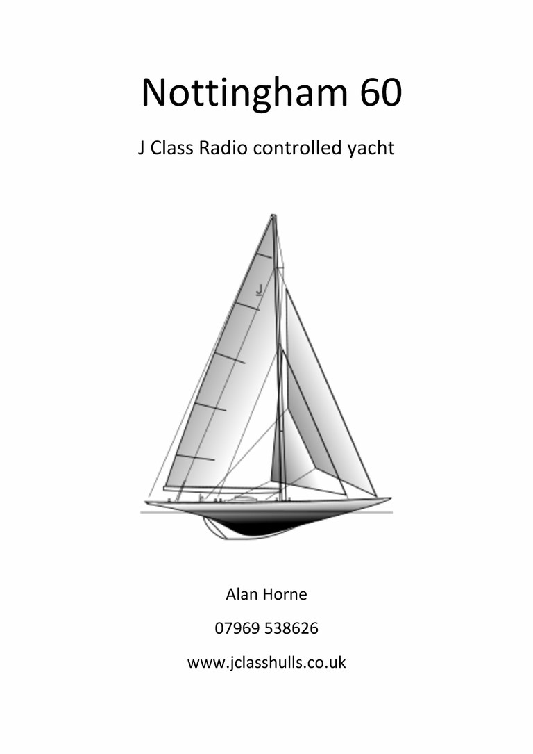
This is the list of my Model Design : Marblehead Class Studio 1 Studio 2 Studio 3 (see cover page) Chine Esterel 1289-M Azur 8 10 Rater Class Esterel 10 ND Esterel Sugar Box 12 Metre Class (Conversion of real boat into Model) American Eagle Azzurra Columbia 1958 J Class (conversion of real boat into Model) Enterprise Endeavour Ranger Various (Designs outside Rules) AC33 43-900 Esterel 45” 1.2.3. FDS-11 Staysail Tuiga (conversion of real boat into Model) UFO 22 (conversion of real boat into Model) UFO 28 (conversion of real boat into Model) Delta Rig 65-Cat 80
AC Models ( new designs or inspired to America Cup boats) AC100 (5 conversions to RC Models: A, B, C, D, U) AC120 (16 conversions to RC Models : Alinghi, China Team, America 3, Areva, Desafio, BlackMagic, Luna Rossa, Mascalzone Latino, NZL20, Oracle, TNZ, Victory, Young America, AC130 RG 65 Class CD-65 Esterel 65 Fuxia 65 Trap 65 65-CAT IOM Class Wild IOM-ND Lazy Footy Class Footy Esterel Futinett Guinness Record (Smallest 2Chanels RC model) Mini Freccia & Servos Servos Modified HS725BB Modified micro servo LS-3 for Mini-Freccia (Guinness) My plans will be listed at the end of this book as PDF prints, but short discussion and some project drawings are presented here for the analysis purpose. International Radio Sailing Association is ruling some RC Model Classes, while other RC Models comply with National Class Rules. 81
Class M Rules Short List Mast height 2160mm Hull LOA min. 1275mm - max. 1290 mm Hull Beam min. 100mm Sail Area 0.5161m?2 Dept max 660mm Interesting from design point of view since no limitations are imposed for the Displacement as well for the max Beam and hull Draft. Further, according to the sail's formulation, the real Sail Area can be 7200cm~. 82
UTWO}071LSl68 0i|61OZISrl8 SSO[OD W dVA*OaLl7ed 9gOe0IS¢rV|D BCG86uZzsm2y ,BA.u\riUmyOs O N|n %AIC 83 .W9s(O2pS7eJ=1yaojGuq0)ld|
Class M Rig dimensioning Example of Classic Sail Plan type A Basic SA for Class M Type A Classic The Sum of partial surfaces in yellow = 7200cm? against the 5161cm? from Rules 80% of H forestay optional surface 36 of Luff > ror) HS N As N co a1 – =Q) ar) G8 ‘ 0 Datum line 84
Example of Swing Rig Plan type B 9%, 8 ue Type B Swing Rig 4 9.5% T 182.76 8% } | 270.80 7.5% 65% 4 | = | cc at k 55% a i 3 4.4% 73% 35.3% 355 +) 85 3 |
My first “modern contact” with RC Models started with the Marblehead Class, a beautiful model with a rather tall Rig. My first Model was Studio-1, which could not be different since was studying Naval Architecture. A year before in 2003 I met at the YCC in Cannes a brand new Dragon made in Germany, the Hull was made with laminated wood, I This picture shows part of my Lab When studying the constructional method I believed in the exceptional solid characteristics offered by that method. Later I discovered that the glue adhesive was adding too much weight. Probably I did not found the right method for bonding 86
Studio -1 This was my first trial with Strip-planking technique using mahogany veneer of 0.6mm. Studio-1 Was almost a disaster in terms of weight since the hull alone weighed 1035g. The major contributor was the glue used being the UHU Hart. The total weight was 4460g and the waterline was moved up by 2.5mm putting the waterline out of specifications. It became clear that the technique of strip-planking was not providing the expected performances unless the bonding process was revised. Studio-1 was a nice looking model, but a failure as an RC Model! It was necessary to go back to the Drawing table alias my PC screen! 87
IsowedpAalnguMyJB st.|n E She “e FS OIPNYS a Nice looking hull construction but poor performer! 88
=aL-OIPMS | LeSyqHwozZ= Ggé:WEsD Oe:lwo Oelwys: 8“JSwEi’0sp WO:D0e’q6L y‘OZU8W>SN9DpL(}ApTU4e>NOYs) [POOH ‘JOA Q‘J>IONAG fo} 89 Uy“JOA
Having missed the construction method with Strip Planking technique I started manufacturing a series of composite material samples in ; % 6 10x10cm = | dm? 91
| CLASSIQUE: \0 AO | A ee a ts 4S pom = 7504, f Potysti@eNe ExTRupe > Balsa samples with relative weight per dm? I tried a different combination of tissues to make the new Class M (Marblehead) hull of 1290mm LOA using 3 layers of Fiberglass tissue of 105g/m? or with 2 layers of Carbon tissue of 93gr/m?2 + | layer of Kevlar tissue of 63gr/m2. Decided for Carbon-Kevlar-Carbon sandwich Kevlar was introduced to compensate the Carbon fragility against shock while Kevlar is very strong Epoxy resin being the bonding compound. It may be a “standard” for my future design, although 3 layers of 80g/m? of glass tissue are not abandoned This plan called “Studio 2”, introduced a round stern, an imported idea from northern concept design like Nauticat or Fischer boats. I was reading that this stern was behaving better with rough waves. The Water Plan was a symmetric one after reading the Model Racing Yacht book of Priest & Lewis edited in 1954. 92
3yoap’uldgcUst19xi:— we q | O17 wo UJolp TrOuA “[OA 8$9 €£WWl9d Ging “IPATpeu a3sse weaoyjdsiqOIGALSPIEXS6ITsuosOuSaWI=PuEldWuOTE G/T=r69 o189By | [44 [|P‘jWeIMd‘MNTjaeIYsuOplrpAtJdueainmqs9Q¢Z£S67Z1UOT¢0g1L9PE1E°m222ew%0ouo9w9 oasoaehzefe0s°gLb9’e%eSPv6Z—s?)oWarie—y8—lMpih|||copPs:eaze Drawn a new plan called Studio-2 u1=cIO_JEoewXDT’9sGnCuSHg AofB1aeipj:sNq;g]Q 93 yo g
Some of the pictures taken during construction: This hull appeared too soft and therefore some reinforcements where introduced 94
Open view of the Studio 2 servos integration 95
96
Studio 2 Fin Box centring and bonding before deck integration
Finally Studio 2 reached the water! 98
The sailing performances were rather good since the expert skipper managed to win two races under medium wind conditions. Here the experimental sails made with transparent flower packaging film. This model was weighting about 4266er, still too heavy for what I was aiming : 4000¢ ! 99
I have experimenting other constructional techniques like the carbon- Balsa-carbon tissue sandwich as well a combination of Kevlar tissue and Aramid Nomex Honeycom 3mm. 100
OU IDA ML *4, { pat The init ial idea was to obtain a rigiid and light Hull… I got two consecutive “failures”! Honeycomb des-bonded probably because the vacuum was not used! 101
Studio 2 female mold was offered to my Club in Milan, but I do not have any records that this mold was then used to produce Class M hulls. AW ie) as aN S ms y TM 102
- an experimental Model £ B e L * 2 l x P E 5 O o = ‘ ” v X s 0 t 1—eY8sFPtaRIumOMo)dT,zS toSJr 2orYDa e7NilOoFr g9J60-4) =oa1n s$ js s Z Aa]sBOUTS 9izaun |IN}5)OADSYNd a seZ *,a Studio 3. 6|921 2 o 2 N Sie rt o o ~*~ 7 VU2WDOAI9TPdL U1G29nYs6PIFeESTCOYwURL – 1a9upreyg SybUsg RCD is0 2d6PLt fo—_t This is my third Class M model and again an experimental design. 103
During Master construction 105
Studio 3 construction continued 106
107
The Rudder axis is a tube. Inside is supposed to pass the string pulling the Foils 108
Another experiment! Rudder with adjustable Foil 109
The foils 110
Studio 3 Fin construction 111
~ — 112 ey by
while overtaking a Margo with ‘B’ Rig While overtaking a Margo with Rig type B 113
Studio 3 Running 114
Almost non wind ! 115
Studio 3 * * swing rig 116
The Studio 3 proved to be a fast model, therefore I considered that this project was another exercise to improve my design and construction technique. Studio 3 revealed nevertheless a final weight close to 4300¢ Actually, it is resting in my garage. Still considering that the lighter boat will be the faster being all other parameters the same, a new design should take place in the future including narrow deck configuration. I recall that this option was the answer to an Off-Shore Rule that penalized wide beams. Modellers found out that, in spite of that restriction, the Model hulls were offering better directional stability with also some gains on the weight (narrow beam). 117
- 6 panels Hull M Chine 6 eer! qing “ysuoD 5 g10r Bole 6.0 jOj0] y By Jappny [OAIaS TOMAS jooy yoeq —._ 60z6z | oS ses 6 o00¢ ‘puaddy Be ry 1dSd jOL 56 0810z6z ginguly 6 SZ 40g 591 5 0z 5 se 5 zs . Qing HOUS 118 4JOuQ wpeqm wipeg M1 Vo! Sri 5 09r Wu 81 UI OF wus [1% WU 0671 WU SIZ! zLe
I do have designed another Class M that I called M Chine 6 This model was initiated after reading an article about the benefits of a chine hull. Classical construction with shadows and balsa panels to make the Master 119
The Master 120
Just de-moulded 121
Finished Hull weight 259¢ 122
The idea is to make use of a Radial Jib Boom y ¢ ee oN Piety beg eS) 77 | . $ r iia ite LET The old one revealed to be too heavy. The New one needs more thinking about interchangeability! 123
knitting needle axis free to rotate ring stop Down goes friction | missing internal tube actual \_ Radial Jib Problem ! ring stop Up Ls = ring stop Up external tube Next !! working on next full carbon !!! M Chine 6 panels still under construction 124
RG65 Rules short List: LOA 650mm +/- 0.5 Rig height 110cm max Sail Area 2250 cm? max 125
RG65 was a nice discovery when I met Pascal Delapiere in Nice. We were not living far away from each other. Pascal was recently returned to France from South America where it became familiar with the RG65 Models. http://navi.modelisme.com/article286.html Probably was him that introduced in 2005 that Class for the first time in France. Easy design and development model at reasonable costs. An excellent “test bench” from my point of view. I was really curious about RG65 and started to design some hulls. The first CD65 with an “L” shaped Fin did not sail as I was expecting. The problem was the centering, solved with the Bulb reposition in the “T” configuration. My first model was sailing as most major size models and did not appear to suffer from the wavelets and was responnding well to the % sails a rudder adjustments. 650 3829 — swingrig | —— Characteristics TM — n a — Se 5 —* = — — a |. ee | rz LOA LWL Beam Draft LWL Plan \= (A | 2< 650 mm 595 mm 144 mm 285 mm 519 cm? Hull Surf 1320 cm? Hull DSP 998 cm3 Appendix tot.DSP 110 cm3 1108 cm3 Bulb 685g Mast 110 cm SV 22.45 dm? Jib 25% design ClaudioD 126
As wrote, for me was supposed to be a "Test Laboratory" I started with the CD65 Model, hereunder, a series of images referring to RG65 modeling. I use images since more talkative then words and less spelling errors: 127
Several paint layers used, aiming to get best finish for the mold fabrication 128
7th wax Ready to start the Mold construction 129
After 9 layers of fiberglass-epoxy of 200g/m Detail of bow cutout 130
kevlar & glass 13 & g/m? 131 eG
132
O) ‘2, SO LD qe fer Ma m boom wiit h Park Avenue s 1mu lat ion ! 133
Hy i Tt ) iM all t ~ m | Mh u { 4 Me, 3 ~ yhs z V/s ; Heyy es Gi th TM This series of pictures are describing my first RG65 design. The model proved also to be very fast as such to reach the critical speed where the generated wave was initiated at the Bow and terminated at the Stern 134
135
Collision route or priority matter? UO a) wy OQ. i © > .) ne) — © en) iD) a) > io) —>> iS fae)ear)iStoy3 — © —>> a) io)io—_8) ot =
The Delta Rig Rules Short List New experimental RC Model Mono-hull RG65 Mono-sail Mast After height 1100 cm Sail Area 2250cm? 137
The idea to develop, at model level, this type of Rig initiated when reading the Philips Bolger book: “Boats with an Open Mind” Philips encouraged me to go ahead with the modeling of the “Staysail” design. The real-scale boat apparently, as reported, was planning rather well. This design was developed in 1922. It was so good that the builder decided to hide it to avoid that already placed order would be canceled in favor of the Staysail boat., Series production was, nevertheless, finding technological difficulties as the Mast rig supports and Hull strength. No Composite material existed at that time! The first Staysail real-scale boat was the CorSair 24. I have made a new CD5 hull aiming to build a Delta Rig Model. One of the major questions was related to the longitudinal strength of the Hull as it was found in the 1922. This is the basic idea. While America Cup was passing by, I said that the Dragon used by China Team was a nice drawing! Here after the difference between a Classic Rig model and the New Delta Rig Design 138
OOLL 2175cm? 1320 cm? 815 cm? 36% 218 mm ——s ee 435 mm AQ5 229 mm 510 mm 650 mm Blue Dragon Cat Rig Blue Dragon Sail Plan 2250 cm? The Delta Jib has the same sail area surface 139
RA Adst A VOVVVV VV MS620M a Hull de-molding and excess cut out 140 PW
Bare Hull weight 76g Delta Rig under assembly 141
Changed color and Air blower testing 142
i SRY AME Py > Wy, Sta Julien when was playing with the Christmas Present Only 8 years old ! 143
YOU TUBE VIDEO 144
The RG65 Saga continued with the Trap 65, and Fuxia 65, but never LosSO reached water ponds. a7 With Trap 65 I have designed a new type of Rig where the Main was supposed to acts as a second Jib, not tested yet…. 145
RG65 Bulb Rules Short List Length 650 mm Mast height 1100 mm Sail Area 2250 cm? 146
The rudder construction technique I use is always the same for all my Models. Lead foil of about 1.5mm thick. iN | 1/2 bulb imim fead trames 147
DELTA assembling the lead layers 1/2 bulb almost shaped 148
2 half bulbs glueing _ | finished left only fixation holes 149 Bulb
The CD-CAT Rules Short List Experimental Model based upon Class M Hull Mono-hull and Mono-sail with Mast after Sail Area 7300cm? max Mast height 2050 mm 150
The results of the Delta Rig, suggested to enlarge the scale and use a Class M Hull. To accelerate the construction I used frames and Balsa plates covered with Carbon-Epoxy . 286 mm —— io —|__ 7 |) Z [ 4 cB / — /-——~L_] 9 1220 mm LY 5 a mm hull lwl mm hull draft 54 mm hull surface 32.85 WLplane 14.40 dm dm? QE deck surface 17.26 dm? 4 =1 | pataras bas et haut 0) 4 by C. Diolaiti a Sy aS = fi f alsa/carbone ~ “LY renfort typique cables mA ipport > | | “> alnghi ee a << 1200 by ClaudieD A beautiful model realized by Marcel in Switzerland 173
Typical AC120 Sail Plan IACC 120 SAILS PLAN 78dm/? 35% Jib CV at 34mm from backside 75 | of mast 174 1360 — 500 80% of 1700
—— AREVA 6 FRA 93 kK 499 Appendages Total Volume 480cm3 Total surface 420 374 Boo 1108cm?2 = Lead @10.5kg/dm3 305cm? 270cm3 , r 2° tilt ad 28509 315 These are the typical appendages used for the AC120 models Since 2010 several things has changed including the revision of the Rules. The major contributor to keep alive this 'Class AC120" was Renato Chiesa. Wish this "Vintage" Class to continue in spite of the actual America Cup changes. http://www.iacc120.it/intro.html 175
NZL 20 adapted to AC120 Class This is one of the models I liked most, was used also for experimental purpose concerning the Hull external finish with Red Gel Coat. At the end was not a good idea since too heavy. The pesnjou . MOINVAZC tovOwZlL tSWu92hei1d4 J3wyIPuOY 9al2Us% a0eiswngz yU2WIR18l9PqL 42%0'8L sHabepzudryYWF6OSLq ugOwSlnLdeq d19o50 g%5'oC 35 ~ 0ZTW weag O2w plan : aSWeDo ~ =veo w 176 O@P O9e SIwUB¢A9D0Y8
\\ Curve of Areas | cm? 19.35 4226 6092 6961 6823 70 65 60 55 50 ry 45 40 i Z _ a 05 65 60 55 50 40 % ce . -3.5% 10 i 30 25 %& Fe x £ 00 9 8 enn? 70 f 10 10.96 45 i 15 27.96 — Fs 9 4531 he f 25 5909 7 403.69 x 9.85 = 3976 cm3 6 5 4 3 2 69.31 x 98.5 = 6827cm3 15 10 \ 05 00 i 0 CP = 0.5821 Jib 5021 cm? 2781 cm? 574 55% of Main 445 ELL LALLDATA SVONOUN SB Telecom ER TT LL LA hdd aD MILPP OVONOTA €12a aa eeTETEETTITT NEW ZEALAND NEW ZEALAND 177
178
179
182
183
i { ij epoxy resin. All my models shall go for this routine work 184
Generally I use Peel Ply just to remove the excess of resin. The Peel Ply ribbons will be removed after two hours max from the polymerization process start. 185
186 black color ~ before wet , y
The Hull after wet sanding and ready for wax application 187
78dm? Short Mast with genoa Oo Te) ray Oo i 283 55% of Main 445 \ —— Datum line Typical Sail Plan for an AC120 class model 188
Vertical Servo Arm in order to keep the weight as much as possible close to the centerline Mast support - ie Fin box BMS 860 DMAX+HS 18.8kgcom @4.8V 54g 0.18 sec/60° —_——_— oD Hatten} pulleys vt = 20> + 44 – S N =. ~306mm -—— 121 —— sheet travel Fin _ 189 89 str “
shifting servo | = \ \ \ The servo position can be chosen as the Fin Box allow. There nevertheless the interest to move the weight above the LCB or Hull center of gravity : – : : vent Pill Pigmen ent 1c en Darey Pigm y me | a: .| aa 1 clair vert. ouge CadmunRed light m u i m Cad 605 R JE— EL N— — —e ‘e sEN 190 ES ¢ Si : =
iae l i g e a e ae 191
oC 3 feb 3K G89) = | still gummy after 3 days About smoothness verified with flashing light i Surfclear } EPN246 192
— ee The Real NZL20 was equipped with dual Fin while the Bulb was kept in between For the AC120 only one Fin used 193
AC33 All started at the time after the 32″° America Cup 2007 when some indications where given for the future America Cup event. Press published some drawing view and indicating that the future Boats would use more sail surface, no Genoa but with a Bowsprit The Alinghi Syndicate, winner of the Cup in 2007, proposed to introduce a new design concept with the AC90. My model was called AC33 I used the Class M Rules but also the AC120 Sail Plan 194
This is the anticipated view of what could be the boats for the new IACC 120 2007 America Cup. 195
AC90 : Hull close view > Very happy to discover what the Nautical Press presented as such that I started designing the New America Cup RC Model. I was happy also because the RC model could be ‘launched’ before the America Cup Event. In 2009 a new Rules were established for the 33TM America Cup This was my drawn 3D artistic view: AC33 RC model by (audicD Servo cover Fin Box 196
My first drawing fort AC33. iByrByIe\aGpng608z g2V¢CuyBbinseaige38w0oTs/r No Bowsprit since not accepted by the Class M Rules 5 1 NS, $9 a7d9?0 4 i = OLPE-56S68h4=29P/INH moszDe2 439uALNIadOV yBeEwS “pas ue 197
| 115 \ Two Beam options AC33 | DSPL 3522 cm3 @ 230mm beam DSPL 3698 cm3 @ 240mm beam 2. ee i CP 064, 10.72 26.26 36.47 42.63 44.86 41.86 Fb Ie | 26.89 16.74 6.82 11.00 25.26 34.51 40.47 42.44 39.79 33.90 25.49 15.89 6.47 SS 55 -. to 25S 7 AE 2S mA i Zz -7 2% ICANT 22 se . o 70 Beam 240mm 9 8 7 6 .. |-beam 280mm 25 -“ pS 25 oa SS “< co —n 5 4 3 2 1 Sis Fava 0 LWL 128 cm 288.96 x 12.8 = 3698 cm3 44.86 x 128 =5742cm3 CP = 0.644 LWL 128 cm 275.22 x 12.8 = 3522 cm3 4244 x 128 =5432cm3 CP = 0.648 While preparing for the construction, a new idea about the use of fabric tissue replacing one layer of Glass tissue popped in my head. The motivation was due to the possibility to have various colored surface difficult to obtain with the classic painting methods. The cotton fabrics of "Kaffe Fassett" were a source of inspiration since my wife used for Patchwork and Quilt. cotton fabric 1129/m? Typical sample Kaffe Fassett Cotton fabric 198
Tr Strip Planking 199 Ks oO cn on me= —wre —oa -— —
Strip Planking almost complete 200
pa? Bs, > ~~ :
Filler 202
y ie = Hulil eTpeI= glass laminat ~~ , +4 fm 203
Water Plan verification at 20° tilt . “eee asi =ee id o – Colored water with blue ink 204
¥ r a < oN ‘ ? a rs et ue ~ oe — Paget aif v soe Ney Be lt A te) i~ Gog- > U A ~~ ar 4″ $1 y “a ee _o—€“-~ + Ste a et oe Oe ‘1POTTY ; 5 Wes neae eS ~ ~ al) Before start hull lamination on male mold, several coats of wax are applied (here Mirror Glaze used) 205
t } 2nd layer WW 206
cotton fabric laminated After lamination with the Cotton Fabric, 2 layers of Epoxy glass of 50g/m? are added 1st layer glass 50g/m? 207
Care shall be taken with the brush to avoid creases. Brushing diagonal movement from center line to the exterior 208
209
Hull de-molded with back light 210
Measured 3D3q Expected S17/g lamination sequence glass 1.05x 44 i =46.2g , — swe er cotton 120×44=52.84 glass SO. 50 x 44 = 22.04 glass | 6 i Fe , : fs §=050x 44 = 2204 Total tissues 143 g Assumed 55% resin 174 g* Total laminated hull 317g * cotton may absorb more resin Hull surface Cotton tissue apparently is absorbing more epoxy resin than Glass tissue, therefore an increase of hull weight it is normal. 211 an ae
Because of the direct lamination without vacuum, an uneven surface will be present. A layer of contrasting paint will be used during wet sanding to smooth the surface. O Oo © oO -— es as ST 80 OY © O WZ ae 0 i OS = = < > Se 212
Progressive surface appearance during wet sanding 213
JSO8B/U\NS JBHaulypes 214
> > i“ = ) for R udde – Fin Box and hull bottom 215
Rudder balsa core 216
Rudder weight 25¢ partial film adhesion ? — 217
Preparing Hull integration 218
219
r7. eGa.it7 “| :%|oe 79″. ys AB2oralik1 oulPwSea.de-ANEoRB:fat aonoghaset3trbnfkyTPfBpHm*RciehEA9s =so d O0“26JAWzINSLveH [ubyap les ued Zupnryg zWPGS-8h ‘gYvob- @L]i09Ls
230 oOa 6 B7—e t:|SL€ —o* L€| s+ 1Z€()I— &eS4c6=Q}~ < | —4g=yO€Lu—k g lLu— 2 g.Lus—kNA g ,LUWY— S55 S| XDOUW 0 91 LULU
. . 7 © AC1 4
232
—_— 235
236
polyester filler
238
240
» s l i a per n | = Pad —
O. ‘aa © ©: 4) = c ©) for Qe coat covering —... 242
+st-coat.. f “- ie Pei \s oe A \ 243 AX
-WPG' Sz X zP/56'p = BL} |jny }UDIOM ||NY Asou} 4417S -pZB|eW+XfUIl/iGS6o9s'c
245
246
247 of a * *+4 “a ett » * - Sint oes ak rs3 A 3 y oS - 2 5 dalle ae Kae fs : be of ie & * oe 7% 7% eu Ya en >
248
tlie AL, MLiy ‘ oop ae oo boom hinge detail
? 250
251
“a, 1 | Gourmet di. cl. 5 kg \ sath | Pa ¢ sensitive computer 252
253
glued.on 1 lead sheet 254
255
256
257
ez. Laz rere 4 o* rT pg / VF eee “6 7 Pate + rt, + 9 Ame € ae ae A Ig tko eH? kg -5kg 258 iS ee es
259
vena E Re ESR SER o SC MS AS * SmTaE te SS — e S 3 \ SSwertvaEhe i = a 260
Just a chair to search for total Centre of Gravity 261
2 aya iay a(n ’ S Pato to) ay daly ay – ~ Oa < > ; a fe ‘ ti ¢ al – 262
263
265
Fats ae \6 = 4, iP PITAALD, A fatefJttheegfitaA * g = S R2 266
Bey Vf Ks eTPSON/ i ly, vy if jf, 4 Z dy 267
268
|! e tool to get shiny Surface 0.5mm thick © 269
270
Brit at 25° K —— = De T The Mold is also used to verify the Water Plan just filled with water. 271
272
7 WS, “f – 7 273
274
275
a ; ce 276
277
In August 2010 the AC100 B was launched in the Villepey Pond near Frejus in France. It proved since the beginning a very well balanced boat and also surprisingly fast Model. Some Video I made and visible on You Tube https://youtu.be/RAMM_z_q3al https://youtu.be/EdyHr9nLUY Y https://youtu.be/ UWjuL5hQ_ Y https://youtu.be/UggSPHMYwRk 278
Ten Rater (10R) Rules Short List Rating: LxSx8=10 Example 1 : LWL1.25mt x Sail Arealm? x 8 = 10 Hull length 1.3 to 1.8 m Displacement 5 to 7 kg Sail area 0.9 to 1.1 m2 The draught, measured to the datum water plane, shall not exceed 700 mm. 279
In my design list the Ten Rater had been always a Must that one day I should build. This model is the oldest design known. 10R designed in 1897 was already using a long deep Fin. Only 105 years later America Cup Boats adopted this type of Fin. Official Rules were issued in 1890. Before discussing my designs, I should come back to the Local Meteorological conditions that need to be considered in order to decide the characteristics of Model Design: In my area close to Toulouse city in France we can expect the following: Mois de l’année Direction du vent Probabilité du vent >= 4 Beaufort (%) Vitesse du vent moyenne (kts) janv. févr. mars avril mai juin juil. aolit sept. oct. nov. déc. Année 01 02 03 04 os 06 07 08 os 10 1 12 1-12 > > a» > a» TM 4 ’TM~ “ > “ oTM~ 33 24 ss a wi 30 30 aes 29 g 8 8 8 8 8 8 8 33 35 9 9 i +0 35 | aS 10 2 S L5>SS SS ES 8 SS eS SS SST data from Winadfinder.com From above diagram it can be observed that the average Wind Speed is 8 kt from June to December nevertheless 25% of the time the wind may blow up to 14kt and more. It is also noted that the predominant winds are only two, one from the North-West and the other from South-East warm and fast during summer. 280
To avoid surprises better to take into account above data, for instance considering wind speed of 15 kt… Above 10kt wind will be better to think about another Rig ! Certainly a so called “All Round” model may be a serious option. I will take into account several parameters like : Prismatic Coefficient Sail Plan & Area Displacement Main Section Draught LWL Appendix surfaces and shapes Bulb Beam at deck and water level Entrance and Exit water angles Curve of Area Rudder Control wheel Prismatic Coefficient: Because of the weather conditions, I have learn that the Prismatic Coefficient should be chosen carefully. Reading various books I have collected the data about the Prismatic Coefficient and found a lot of variations as depicted in the diagram. It appears to me that the Naval Architecture is far to be a precise science. 281
Lodigianil ? _ 9.70 University Ve Paris O 0 Gutelle () 0.65 Douglas | =H lias: 9) 4 +— 7 2 0,60 a 0.55 Delft Tests e Ral DB = Pa ie 3 Se 3 0.50 0.2 f |a | | | 0.50 0.3 a | t 0.75 0.4 ee 1.0 jay Red | 0.5 t | 1.25 l t 1.50 0.6 | Of US : { 1.75 i Fn Froude —t— ss F|osOLr!g —.UZ2D|6qF joa: = ole; mu qnUotdu]m \ \ \ \ ry 4Of9l0das DOUBHLIN) —YovajuUsoS _ . Wdous} 304
Follow a series of Pictures describing the constructional phases 305
306
Epoxy filler all over the hull 307
308
Supports used to allow external tissue laminations 309
310
= © = O Y) © 40) 311 re) a fas
312
. o: Ot 7 A Fe, oye ore 6 27OF eFee seer fe tee Rte Mego fee fst 49 OFe an Fee Se} oer © Feet Ons O28 Tae = –*, 4 Cade fap alae 2%, PEELS Oe: ree, tae peed os anes 24, peneS Hae27a Seer Brae oea ater Fae Atse 8 FO se ere et ttoe tare sfepaer 2: eags 26 f eS 27, Suge <<. fF yee ARIE ee = BOLE Les whet Pat 7Foe eb OF, Stead ‘5 Koo sine Zee Bern gee tee aed tea PAIL LL, , ete (ge 80 ae rf : , eee, ¢ “ ; pated etah y AEA. : : ADE / : ogee ¥, “i EO LP AT (ao ; ra Vs= a7, 7 a : wee 7 Z, 3 ; re: Saat “; ; fe 2 : Z : 24 ; a - oP , Pe Bhs Bd y iy ed LAE Hes OO sag ate Ps s Oo Nise Letaeates 2 tte Py Sd * ag weds T¥,AAta 4044, vA At4 eles ge 7 aan Mee . As 462 te: awe ’ me Leer ie 25 eee oe (2 Mire, Fat Ce oe 4 oS 7 ig P 5A S tae * AE Sapp i eit pad wee. ian ae, a Ms t70tigfetethee PEL Gtt PLE 14e pdt G seee oe. edt Logs) 4 OS fee AF rere 2a, 313 FOS G2 8 iba eae in 2eae (ee 7 Cade A TORII a So tar a y)a4,4 aga sees ‘ o 7.Wael geeas Stee ater arseseed, cage4ak tee LTTE ad ae ate A Bt A VEPE ede eA Aree AEAE OOS.rte Sate oeAbeee 6 2047 Bese ee Ae) Pree - 48. area Zee seabade Fee Fen 2728 wee s2 POE rea aa ef4, Lies ease eer ’ as OT IY Sete 7} PHA
314
we + >. t ,! wet surface. kai —_— 43-900. cues 315
For the time being the 43-900 story is ending here. 316
‘123! Born as “OneTwoTwo” project and changed in ‘123’ This model is developed in order to verify the possibility to drive the Main and Jib sails independently as on real boats. Among that care has been taken to draw a model with a modern look outside the established Rules. A bit shorter of a Class M. LOA 1230 mm LWL 1150 mm Beam 173 mm Wbeam 155 mm Draft 480 mm Sail Area 7800 cm? max. Dspl 4000 cm3 min. 317
Next page shows the dual winch set-up, one for the Main and one for the Jib 318
eSZSofbé/t82b Z 9ae$ ‘ § z f 0St -9L66t— f wWgeiSanq-/\ =W6zL0i7p92sT SE| in,ql8a |aoP d:SF URid-MZDOTEVg or oOZrg&éA¢¥eziSn |[e =j«E6SGILuMWRZ:1TwWei/6Tag —oaVgs-2U4BO9lP}qAr%jyWei7Fpx6nu5d E&shjo6n8e9y07f—”5As X$B9SD2ZE’/G01=°6Ldle WLYZUOTDE iESCR @%C1E- In order to operate the two winches separately, has been necessary to modify the Transmitter Joysticks functions. This resulted in a difficult appraisal of the servo’s control. 319
10 272 LF 320 4) |) 2B 1230 1150 [544
The shadows have been modified by splitting hull from deck: sa + t = i a =< —a i Peea i y we Be ss 123 s had OWS ( WZ pee 321
uy N “i | 7 /7800dm* 183 © 460 N }— = 45 1219 as 2 Om Oo» = H——, S 322 6 1483 > 4 CE 3 i | = st 26/ 1767 re be O 5073 cm . a 5 8 g 963 1em? BS 51.8% itl L— 375 _——— : | 19.5% 473|322
323
Appendages 123 TOTAL 442cm3 a — 75 —| | R1 R2 65) a 5 = tA 321 se: 129cm3 —. ‘7 se © 8 © “ 37cm3 276cm3 —_— ae 324 a ae S date, EE, —~
During the model design one of the first activity consisted in the shadow drawing and calculations. Here below the evolution from ‘121’ to the final ‘123’. The chosen form being the one offering less Wet Area in spite of ‘121’ having less draft! ‘123’ was retained 121 cm 123 cm it S oS | 4g.2 —— ” a O IO tA Fn 90,0 S 3 weT AREA 1558cm/? WETAREA 1589cm7* +1,9% 122 cm 122 chine |__ gg? |___ 003 WETAREA 1616cm? +3.9% net r— 44.9 = weTarEA 1687cm7? +8 270 a 3679. 3), N 80,9 a \\( a S
One of the concerns was the tilting angle versus deck sheer line drag. Rounded corners helped over 28° of tilt. classic shapes ha | Sa custom shapes SZ : a NS WW mn TMN J} i reducing deck sheer line drag – at 38° critical “123” design 326
Weight follow-on July 30 – 2012 New Hull and Flat deck Hull 3x80g/m? glass 152g Deck fulllaminate 2xl05g/m* Hull + Bow + balsa stern + stripes Glass reinforcements resin for reinforcements Hull weight update 82g>I105g 176g 33g 33g (measured complete} (+249) (20.0 dm? of 165g/m?7) 242g + Deck as is 105g = sub total 347g Today 14th of august 2012: projected weight Hull + Deck {before supports) 347g (measured) 2 winches {65g} 130g (measured) Rudder servo Battery (5x AAA}-6V.-1000mA/h 33g 64g (measured) (measured) Receiver 12g Fin Rudder Rig Jib servo Trim ISig (measured) 35g (measured) 222g (measured Hitec HS$-5245MG sub total 994g Supports : mast eye bolts fin box Fin box bar dual winch support bars servo rudder supports bars rudder trunk support Jib anchor support fairlead support Paint/primer sub total 32g 5.9g 22g (measured) (measured) (measured) 5g 9g 7g (measured) (measured) (measured) 6.9g I3g 3g 35g (measured) (measured) (measured) {expected) 138.89 Bulb 2920g Total 40529 Missing deck bonding Design aimling goal !! < 4000g 327 (measured) 32g
Example of one of the many pages of CorelDraw Mosaic Roll-Up + r3f—oJ1ysIpi9ao°-g'"‘nxBue4m]lwqt|}) 3s—=I-oe~[5c:aE>DJypi9’°/‘djgnuAlw1 esJIy1’po|”a@qgZwM9j-mciuUl I1iJspao’‘’gy7w¢uz-nr{(jZdB|2me4 s|Jyp4ao-0r’u2OgzNiEdn1’!eq” PISsJHar8’w.MpdWOiuU@ne7o-tAjE1Yl9) BsiIpJyuoae’-n‘zd =Fih| TNA1:ces|4( 1: —as’,GLS—ye = i 43 1 ae | eased | od oS. a_e J —!_t- 328
The images that follows are the ones referring to the ‘123’ Construction Phase 329
read Lat|VFesh formes wal fra 330
331
332
Surface Hull Form Control y > short rough Removed from assy table 333
334
Deck strip planking seen from above 335
336
337
Hull and Deck Masters almost ready for mold making 123 22 Ore —_»> 338
acking tape + wax ?! initiate { Tet ATLAS a. F YMA TR ora tad
340
34]
Deck demolded
343
-” Deck and Hull assembled 344
345
Latex membrane 346
away Details for dual servo’s strings and return pulleys 347
Servo’s sheeting path M issing Sails and Bulb 348
349
350
351
Main sail could be better adjusted ! 352
Main not well set ! 353
In spite of the Main Sail poor adjustment, the performances observed were very good. Reduction of weight will improve dramatically the speed performances. The wind was blowing that day at 18kt. Personally, I miss some maneuvers since mixing up my fingers and the Joysticks. Need some training or modify the Radio system control in another way. I was surprised to see the “Nose Up” instead of “Nose Down”. Probably the results are due the centering of the boat and to the position of the Center of Flotation. Video https://youtu.be/fnpIloA72iGk 354
355
if a —_ -_ —_ pom i | _ a — —- ~, on _—— = .— el at — omomer, <1. OF L— — ~~ +. @ mehe Oa
357