- Title. Author. Summary

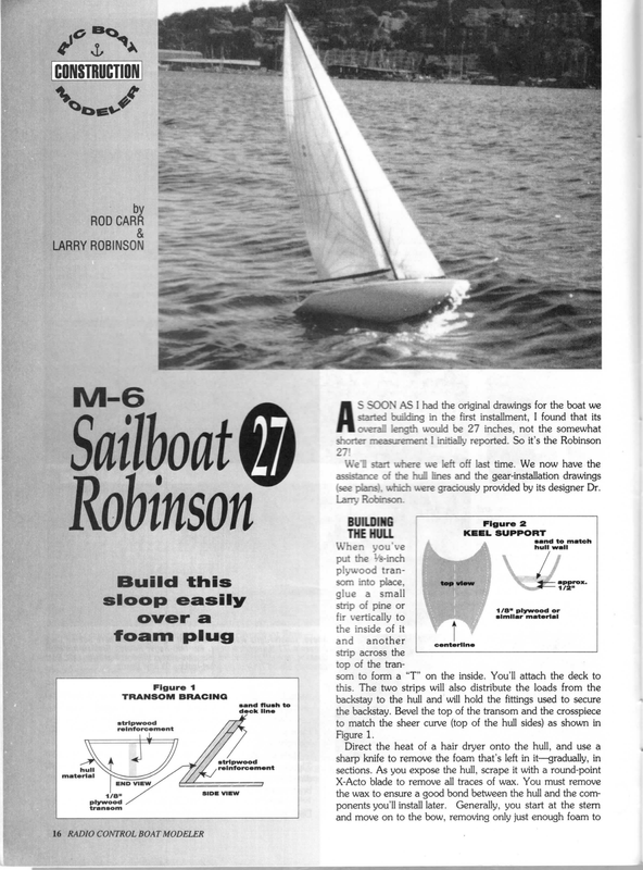
S SOON ASI had the original drawings for the boat we started building in the first installment, I found that its overall length would be 27 inches, not the somewhat shorter measurement | initially reported. So it’s the Robinson We’ll start where we left off last time. We now have the assistance of the hull lines and the gear-installation drawings (see plans). which were graciously provided by its designer Dr. BUILDING Figure 2 THE HULL KEEL SUPPORT put the ¥%-inch ‘ When you’ve plywood tran- Build this sloop easily _ over a foam plug Figure 1 TRANSOM BRACING sand flush to deck line stripwood reinforcement / ~ yi ‘Paaand — approx. 1/2″ 1/8″ plywood or similar material the inside of it \ and another centerline strip across the top of the transom to form a “T” on the inside. You’ll attach the deck to this. The two strips will also distribute the loads from the backstay to the hull and will hold the fittings used to secure the backstay. Bevel the top of the transom and the crosspiece to match the sheer curve (top of the hull sides) as shown in Figure 1. stripwood reinforcement 7 SIDE VIEW plywood i ” som into place, glue a small strip of pine or fir vertically to peryontaal Direct the heat of a hair dryer onto the hull, and use a sharp knife to remove the foam that’s left in it—gradually, in sections. As you expose the hull, scrape it with a round-point X-Acto blade to remove all traces of wax. You must remove the wax to ensure a good bond between the hull and the components you’ll install later. Generally, you start at the stern and move on to the bow, removing only just enough foam to
allow the fitting of the next component to be installed. Because the boat is small, I didn’t bother to install sheer clamps (strips bonded inside the hull at the sheer) or temporary deck beams. A larger hull might need them to maintain its shape at the sheer until the deck has been fitted. Remove the foam so that you’ll be able to install the crosswise rudder support. Made out of ¥4×3-inch pine, the support has a hole drilled in its center to allow it to be slip-fit over the rudder tube. Bevel and trim the ends of the support to fit the hull, but allow about ¥% inch of the rudder tube to protrude above the support. You can temporarily refit parts of the foam and use them as jigs when you fit the support. Use polyester putty to hold parts inside the hull. It bonds well, and you can make fillets by molding it with a wet finger. 1. Plan the radio installation and decide the wooden transom and rudder-tube support. to remove foam. RADIO BOARD Plan your radio installation by sketching the positions of the servos right onto the foam, using the plans and photo 1 for guidance. Remove one layer of foam at a time in the area you’ve chosen for the radio board. To lower the boat’s center of gravity, this board should be as low as possible in the hull. (To check that there’s Figure 3 enough clearance for the polyester servos below the radio | ppm. utty board, push a stiff wire into | Bead et the foam.) Remove foam | Sreumdsme aoc until the radio board fits | gftme where it should go, as Place hull hull shown on the plans (photo | exg”sesk Figure 4 2) hull edge . into putty. Make the radio board out of Ys-inch plywood, using the foam piece you removed = Mitty nes 4 | S4red, | *”°~” as a template for it. (Attach | f4mn it to the plywood with 3M- 77 spray adhesive or its —o | pee * oo equivalent.) Saw close to the | im” 2. Foam removed from the hull will serve as a template when ——— the wooden radio 0a deck line | a 7 cent Figure 5 edge of the foam (photos 3 and 4), then, for a perfect fit, test-fit the board and sand its edges. For reference, mark the inside of the hull to show where the top of the board comes to. Cut the radio board to take the servos, and make an opening in it so that you’ll be able to access the area underneath it when it has been installed. This access hole will allow the bilges to dry out after you’ve sailed in rough water, and it will also allow access to the keel bolts. For stormy sailing, pop a small sponge through the access hole; it will soak up the water that enters and prevent it from splashing the radio gear— makes bailing easier, too. 4. Foam from the hull is aiso used to establish the shape of board can be stren thened the keel support. wooden doubler as If you want to, you can lighten the radio board by routing- out its underside. If this is your first boat, however, don’t bother. Photo 5 shows Larry working to remove every extra gram. You’ve made a place for the radio board and ensured that it will fit well, but don’t mount it yet. When you eventually add it, it will stiffen the hull, but you won’t be able to remove it. Just 6. This shows the finished keel support andradio board p installed in the hull. be sure that you’ll be able to remove the servos. Install them with wood screws that go into the plywood, or into some additional backing blocks underneath (better than using nuts and bolts). Some folks make part of the radio board removable; suit yourself. And don’t forget to make the hatch big enough to allow access to everything. KEEL SUPPORT Make a keel support in the same way as you made the radio board. On the Robinson 27, the keel support is only about 4 table. Notice the ‘44-inch lip glu mermeaee opening. 7. Here, Larry Robinson is routii ‘here. The board has been waterp! with CA.
inch above the floor of the keel. Mark the support’s centerline, and lighten it by shaping it as shown in Figure 2. Waterproof both sides, using either CA or thinned epoxy resin like that by West Systems*. Mark its position in the hull, scrape the inside of the hull clean, and bed the board in polyester putty using your finger to make a nice fillet. Photo 6 shows the keel support below the radio board. Now you can mount the radio board in the place you prepared for it. BELOW DECK Remove the foam from the area where the chain-plate blocks wil go. Make the blocks out of pine, and match their thickness to the length of the bolts that you’ll use to mount them. Bed them im polyester resin, and when that has cured, trim the tops of the blocks flush with the sheer, and they’ll be ready to accept the deck. Remove the remaining foam. Use polyester putty to attach a forestay support block to the bottom of the hull in the posi- tion shown on the plans. The upper part of the block has an integral turning block through which you’ll route the jib sheet hull for the up through the deck to the jib club and then aft to a traveler. This arrangement allows the downward pull on the jib to be well-controlled, and i controls the twist in the sail effectively. (This is necessary with the tall, narrow, high-aspect-ratio sail used on this boat.) Another trick is to use a piece of flexible tubing like the inner tube from a Gold-N-Rod* pushrod to route the jib sheet. Trim the top of the block to the proper height to accept the deck Figure 6 Figure 7 Figure 8 cuTs 1,2,344 Sl) Left: with the hull inverted and blocked level, the rake of can be precisely set. 11. Right: the fillet between the fin bulb should be sanded smooth with 320-grit sand- Paper wrapped around a V%é-inch-diameter dowel. Figure 9 SCRIBING THE CENTERLINE Install a mast-compression strut in the position specified on the plans. and glue it to the front edge of the radio board to ensure it’s held firmly. The top of the mast-compression strut also has a turning block for the main sheet. Tubing that’s really the plastic insulation off 22-gauge wire runs from the deck to the blocks and supplies lubrication (sewing machine oil) to the bearings, which can’t be reached when the deck has been installed. ATTACHING THE DECK Because this is a small boat, deck construction isn’t typical. Cut the deck blank out of ¥s-inch plywood, and mark the hatch dimensions. Cut out the hatch opening and, on the underside, glue a ¥%4-inch-wide reinforcing doubler around the opening to produce a 44-inch lip on which the hatch cover will sit (photo 7). Make sure that nothing protrudes above the sheer, trim the deck until it’s about Y16 inch too big all around, and scribe the hull’s outline onto it. To help you position the hull on the deck, glue some small wooden blocks (68) just outside the scribed outline. Coat the underside of the deck with resin to waterproof it. Attach one or two deck stiffeners to its underside—under the jib traveler and main traveler—but don’t extend them all the way to the sides of the hull (photo 8). Then mix up a batch of polyester putty, using the minimum amount of catalyst to allow a slow curing time (and a long working time). Run a ¥-inch-thick bead of putty all around the deck (0 CONTROL BOAT MODELER
———_— = SPECIFICATIONS Type: Sailboat Length: 26% inches LWL: 21% inches Beam: 5% inches Draft: 14 inches Displacement: 3.01 pounds (ready to sail) Hull material: Resin and cloth No. of channels req’d: 2 (rudder and sail) Power req’d: Wind Sail area: 273 square inches (no. 1 main—154 [RADIO CONTROL BOAT MODELER M-6 SAILBOAT sq. ins.; no.1 jib—119 sq. ins.; no. 2 main—111 sq. ins.; no. 2 jib—82 sq. ins.) Boom: 10 inches Jib club: 7% inches Sail Dimensions: no. 1 main—luff 81.6 cm, foot 24.5 cm; no. 2 main—luff ORDER THE FULL-SIZE PLANS, PAGE 58 (Figure 3). Carefully press the hull down into the putty, being careful not to slide it around (Figure 4). Use a few weights to hold the hull down securely. Watch carefully, and when the putty starts to harden, trim off all the excess, using a pilot bit on a router (if you have one). It’s easier to remove the excess putty before it has completely hardened, but be careful not to loosen the hull as you remove it. Finally, when the putty has hardened, fill any holes and complete the deck-to-hull joint (Figure 5) with an ounce or so of runny polyester resin. Pour half of it amidships into the deck/hull joint, and then tip the hull from side to side and front to back to distribute it fore and aft. Do this on both sides of the hull. FIN AND KEEL The fin keel and keel bulb are next. A boat of this size isn’t subjected to heavy loads, so use wood for the fin keel. I used a flat, well-aged piece of ¥4-inch-thick maple, which I trued with a table saw and a jointer to ensure a rectangular cross-section. Draw the side view of the fin on each side of the wood, then scribe the centerline around the block’s four sides. Fill the scribed groove with CA kicked off with accelerator, then file it flat. This will protect the reference line that will be critical to making a straight fin. The fin’s thickness should be 10 to 12 percent of its fore/aft dimension (see plans). Next, set the table saw to a 2- or 3-degree tilt, and make the cuts shown in Figure 6. Notice that the cuts don’t go all the way through the wood. You should probably practice on a scrap or two first, and always use safety equipment—push sticks, eye protection and any anti-kickback devices with which your saw is equipped. You can’t sail a model yacht successfully if you have less than the originally issued number of thumbs and fingers! The depth of the fifth cut (Figure 7) will depend on the thickness of the fin. To avoid making it too thin, remember the 10-percent recommendation. Fins that are too thin are apt 86 cm, foot 18.5 cm. to cause stalling and generally poor performance. Rip the fifth cut and glue the piece temporarily back into place to support the fin while you make the sixth cut (Figure 8). With a little filing and sanding, you’ll be able to bring it to its final form. Cover the fin with two layers of 34-ounce fiberglass cloth and polyester resin. Sand when the resin has cured. If you’ve been careful, the trailing edge will be as sharp as a knife. On the bottom of the fin, cut a tenon, as shown on the plans; don’t reduce the thickness of the fin; the tenon sides curve inward. On the bottom of the hull, scribe the centerline in the area of the fin and rudder. I devised a simple jig for doing this, and it takes out all the guesswork (Figure 9). I left a hole in the mounting board so that I could stick the scriber through it and mark the centerline on the keel support, too. Using a series of increasingly large drill bits, enlarge the rough opening for the keel in the bottom of the hull, then file/rout the opening to accept the top of the fin (photo 9). True the top of the fin so that when it’s pressed against the underside of the keel support, it will have the rake shown on the plans. SETTING THE FIN The fin leading edge is designed to be perpendicular to the deck, and the deck is parallel to the hull’s water line. So, with the hull upside-down ona flat surface, check that the fin lead- ing edge is vertical, and you’ll know it has the proper rake. Photo 10 shows this being checked. Now clamp the fin gently in a bench vise (use some corrugated cardboard to protect it), and lower the hull gently over it. The hull will come to rest as the keel support meets the top of the fin. Drill a pilot hole for a small screw through the keel-support centerline and down into the keel fin. Remove the hull, and enlarge the hole slightly so that there will be (Continued on page 40) APRIL 1993 19
ROBINSON 27 Club Directory Space restrictions in our February ’93 issue limited us to printing only a past of our complete directory. We pick up where we left off, in Missouri with the Saint Louis Thunderboaters. U.S. WATERS Missouri Saint Louis Thunderboaters. Contact: President Gerry Grosse (314) 225-7726, or Secretary Mark Hunter (314) 966-8355. : Nebraska Norfolk Neptunes. Contact: Jay Putters, 408 Norfolk Ave., Norfolk, NE 68701; (402) 379-2316 or (402) 371-5520. (Anything that floats; gas and electric.) Nevada Las Vegas Mini Mariners. Contact: President Mike Cohen, 2033 Sweeny Ave., Las Vegas, NV 89104; (702) 386-8974. (NAMBA member.) Las Vegas Model Boaters. Contact: Stormi Paykoff, 2983 Burnham Ave., Las Vegas, NV 89109; (702) 735-6043. (IMPBA member.) New Jersey Castrol Motor Oil Boat Racing Team. Contact: Jesse Wilson, 220 Pitney Rd., Absecon, NJ 08201. Jersey Wave Busters. Contact: John S. Gill, 16 Roosevelt Ter., Hopatcong, NJ 07843; (201) 770-1784. (Static, scale, sail, gas, fast electric.) Mercer County R/C Model Boat Club. Contact: President Bob Toth Sr., 23 Manor House Dr., Trenton, NJ 08638; (609) 7719368. (IMPBA- and NAMBA-sanctioned races for fast electrics.) Morris County Electric Boat Club. Contact: President Doug Twaits, 23 Elm St., Stanhope, NJ 07874; (201) 3475765. (NAMBA-sanctioned fast-electric races.) Morris County Roostertails. Contact: Secretary Herb Neelman, 320 Rexland Dr., Boonton, NJ 07005; (201) 335-7666. (NAMBA sanctioned.) Pinelands Model Boat Association. Contact: Don Hermann, 2167 Hollywood Dr., Forked River, NJ 08731; (609) 9717190. (Fast electric, gas-powered; APBA member.) Racing Association of New Jersey. Contact: President John DeFina, 31 Emwood Ave., Westwood, NJ 07675. (Fuel-powered boats; NAMBA member.) Sussex County Cell Seekers. Contact: President Matt Tomensky, 3 Morris Rd., Stanhope, NJ 07874; (201) 398-6016. (NAMBA-sanctioned fast-electric races.) 40 RADIO CONTROL BOAT MODELER Task Force 100. Contact: Dom Baysic (609) 267-6136; P.O. Box 902, Mt. Holly, NJ 08060. (Scale model warships.) New York Adirondack Model Boat Club. Contact: President Steven R. Gordon, 24 Worden Ave., Johnstown, NY 12095; (518) 7622450. (Gas; electric; fast electric; SSMA member.) Buffalo Model Powerboat Club Inc. Contact: Commodore Donald Spielberger, P.O. Box 453, Getzville, NY 14068; (716) 594-2771 or 689-8924. (Sail, scale and power fleets.) Catskill Scale Model Shipwrights. Contact: Joe Callejo, 408A Spillway Rd., W. Hurley, NY 12491; (914) 338-6607. Empire State Model Mariners. Contact: Pete Torres, 3736 10th Ave., Apt. #6B, New York, NY 10034; (212) 567-2090. (Sail, static, scale and fast electric; SSMA charter member.) Long Island Model Boat Association. Contact: President Chris Hoffman (516) 561-1814 (call between 6 and 10 p.m). Address: c/o Aeromarine Laminates, 78 E. Industry Ct., Deer Park, NY 11792. Model Shipcraft Guild of New York. Contact: Secretary John J. Magno, 2012 60 St., Brooklyn, NY 11204, or George D’Elia (201) 332-5631. Ship modelers (sail/power scale). Southern Tier New York R/C Model Boaters. Contact: President Pete Forcier, 2858 Harris Hill Rd., RD3, Del. 95, Elmira, NY 14903. (MPBA member.) Thunderboats of Brooklyn. Contact: John Liverani, (718) 331-7983. (Gas-powered or glow; deep-vees or cat.) Western New York Model Power Boat Club. Contact: Treasurer Bob Miller, 143 Dexter Ln., Tonawanda, NY 14150; (716) 695-5949. (IMPBA and APBA member.) Ohio Cincinnati Model Boat Club. Contact: Mike Uckotter, 2109 Harrison Ave. #12, Cincinnati, OH 45214; (513) 661-3237. (Scale hydros and gas-powered boats.) Dayton R/C Boat Club. Contact: President Tim Dozier, 2601 W. Riverview, Dayton, OH 45407; (513) 278-7704. (Gas; IMPBA member.) (Continued on page 48) (Continued from page 19) room for making fine adjustments. Then replace the hull and, putting a washer under the screw head, temporarily mount the fin on the hull. When you’re satisfied with the fin/hull alignment, add three more screws to secure the fin on the keel support. Put a fillet of polyester putty around the fin on the outside of the hull, and allow it to dry. Complete the job with a little resin that you’ve thickened to ensure it won’t run too quickly. Holding the hull sideways, pour the resin onto the fin and then invert the hull to run the resin over the underside of the keel support. KEEL BULB The keel bulb weighs 0.94 pound. Though you can get into the foundry business to make it, there’s an easier way. Find a 1¥2-pound lead fishing weight that’s approximately the size that you want the bulb to be. Shape the weight with a heavy hammer until it’s almost the same shape as the one shown in the plans. Drill an Ys-inch hole in each end, and epoxy a 3-inch.long brass tube into each. Clamp your variable-speed electric drill onto the tube that’s on one end of the weight, and put the tube that’s in the other end of it into an %-inch hole that you’ve drilled in a piece of wood and into which you’ve put a couple of drops of oil. Turn the weight slowly with the drill, and ask someone to help you true it with a coarse file. Be careful; don’t turn the drill bit fast. You want to grind the lead down, but avoid generating lead powder, because it shouldn’t be inhaled. Check the weight of your “keel bulb” occasionally. When it’s the right weight, cut off the brass tubes and file them flush with its surface. They’ll protect both ends from being damaged. Using a series of drill bits, roughly drill the mortise to the depth of the tenon on the fin. Finish the mortise with a Dremel tool until it can be push-fit into the tenon. Roughen both the mortise and the tenon, and then join them with polyester putty leaving a “small-radius” fillet that will be sanded down when it has cured. RUDDER Make the rudder in the same way as you made the fin. Alder or basswood are good choices for this. In the rudder, drill a shaft hole that will give a (Continued on page 48)
VONMGIE DO YOU OWNA R/C. STOCK BOAT/MOTOR? ARE YOU READY TO GET A DIGNIFIED PERFORMANCE OUT OF IT? THEN IF YOU S00 WE 44 ST, FORTLAUDERDALE I HORA 2,i554 (905) $05-O87F 029 At 5 PM SPECIAL ROUGH, TOUGH & RAGE READYALL THE WE SPECIALIZE IN2 CYCLEREG.GAS |mobiry your MOTOR. DONTCALLUSWEBOTHLOSE. LARGE SCALE BOAT MOTORS SPECIFICALLY HOMELITE w mat -e FEATURE + HD. CLUTCH, MACHINED | MOTOR MOUNT* & READY TO INSTALL {16000 + (NO LOAD) R.P.M. ! VELOCITY STACK,* a. | BIG BORE CARBURETOR, i GET ONE op FOLLOW ONE & ! WE CAN MODIFY THAT WIMPY 25/30 C.C. BIG BORE CARB SPACER,a } MOTOR TO DOA ROARINGD15,000 RPM aeenee EXHAUST HEADER, FREE RETURN FREIGHT. ALL FOR $225.00RANTEE [FREE RETURN FREIGHT) (COD. ADD $ 5.00) BEEtas Nee mew meee me mem cmemeeemememememememe mens mem (Continued from page 40) good “press-fit.” Like the keel fin, the rudder stock should be filed to a wedge shape. This way, the shaft will be locked securely when it’s inserted in the hole filled with polyester resin. From the inside, drill a hole through the hull and rudder support for the rudder tube. Enlarge the hole in the support to allow the rudder-bearing tube to be adjusted. Cut the rudder tube to length with a tube cutter. Then, lap a spare piece of rudder shaft into the tube with an abrasive such as polishing compound. You’ll end up with an almost watertight rudder bearing, and the rudder will rotate on the two ends of the tube, so there will be less friction. Fix the tube in the hull, and make sure it’s vertical before you embed the top of it in polyester putty. with a brass hub insert makes a good tiller arm. Remember to file a flat on the rudder shaft for the setscrew. Select a position on the tiller arm for the connection to the servo—one that provides no more than 40 degrees of throw on either side of the boat’s centerline. More throw allows the rudder to act like a brake and slow the boat. Next time, we’ll finish the deck hatch, install the radio gear, make the rig and test-sail the prototype. Until then, let me have the latest photographs of your projects. Sometimes, the sight of a completed boat is all it takes to entice a new skipper into the sport. (Rod Carr, 3011-177th Ave. NE, Redmond, WA 98052.) *Here are the addresses of the companies mentioned in this article: West Systems, Weston peredeaign. 944 Placid Ct., Arnold, MD 21012 Gold-N-Rod; Sullivan Products, P.O. Box ee North Haven St., Baltimore, MO MACHINED ALUMINUM RED ANODIZED | THIS ADD. .’\ UNT FOR LIFE OF 10% DISCO CLUB DIRECTORY (Continued from page 40) | Maumee Valley Model Boat Club. Contact: A. Harris, 5905 Reinwood Dr., Toledo, OH 43613; (419) 472-1331. (Scale, steam, elecPerformance Model Boat Club. Akron. Contact: President Gary Lark, 671 Sweetwater Dr., Wadsworth, OH 44281; (216) 336-8027. (Open to all model boaters; power, scale, etc.; IMPBA member.) R/C Fun Club Model Boats of Central Ohio. Contact: Rich Ritchison, 1834 E. Beaumont Rd., Columbus, OH 43224; (614) 261-7624. (Steam, electric, gas.) A great offer!—free publicity! To have your club listed here, send its name, mailing address and the name and phone number of someone to contact to: R/C Boat Modeler Club Directory, 251 Danbury Rd., Wilton, CT 06897. Attention: Diana Winarski. A model-airplane nylon steering arm New Picco 45 Big Ports Big BRG- EAGLE 50% PREBUILT Motor Mount, Strut, High Turn Fin, Cowling, and Wing. 7) CAJUN BULLET 21-40-60/80-90 50 % PREBUILT BOAT SET RECORD AT 92 IMPBA INTERNATS TIDEWATER BOAT HARDWARE Picco & CMB Motors Wholesale & Retail FAX: 318-281-2476 48 RADIO CONTROL BOAT MODELER a — ~ Seat eT ETS pene New Picco 45 SET Oval Record 92 IMPBA Internats – 22.7 Sec. Won Straight Away Time Trials YOUNGBLOOD FIBERGLASS alia WITH CARBON FIBER BOTTOM MEE 45-60-90 SIZE No Painting, Shaftlog Glassed In, Fitted Cowl, Sponsons Mounted, Ready for Motor and Hardware | | Slh MECESSONY AUMCRRET emememencmcwcae ROBINSON 27 4.49.00 | 6 PW. 9 PMT. (305) 763-1549 21-90 Single and Twin Sizes 90 TWIN SET RECORD AT 92 IMPBA INTERNATS TIDEWATER ENGR. & MACH. CO. 2406 W. Madison P.O. Box 1135 Bastrop, LA 71220 Phone 318-281-2460