- Title. Author. Summary
- Title. Author. Summary
- Title. Author. Summary
- Title. Author. Summary
- Title. Author. Summary

” ul] wo s8s 5 SANAAAY eS Published on the Seventh of each Month 10 THE 50-800 MARBLEHEAD UTZ) | | ( ED f gully ° Vol. VII, No. Dynal sebasseee sean ing sant sees TECHNICAL. Coy January, 1935 CLASS By THE EDITOR Wy E publish below letters from Mr. F. L. Pigeon, Mr. John Black, and Mr. A. R. Brown. The first two of these gentlemen are well known to British model yachtsmen, as both of them have represented the States in International Races, and Mr. Black came within an ace of taking the Cup home with him. From Mr. Fred L. Pigeon, Hon. Secretary, M.Y.R.A. of N. America In your September issue you published a letter from Roy F. Clough, of Marblehead, Mass., who was the originator of the 50-800-class, although, I understand, L. Francis Herrishoff was the designer, while the Model Yacht Racing Association of America is responsible for its growth throughout America. Most of us in America believe there is room for this class here, as a starter for the younger element coming into model yacht sailing. It requires as much skill to build these 50-800 as it does an A-class model, possibly handles a little easier, but is a good size for the youngster to make a start with and, eventually, see the fine possibilities of model sailing, and then build the A model. As Secretary of the M.Y.R.A.A., I can speak as to the number of models registered with the Association. There are over 160 A-class models and 190 of the 50-800-class. So that when one says the 50800-class is by far the largest class in America, he il is not stating facts. I know of no A-class men who have dropped their A models to sail the 50-800, but, in fact, plenty of A-class men who have dropped the 50-800, as one class is sufficient to take care of, and the A-class offers the best results. Marblehead cannot sail any larger model than the 50-800 on their pool, it is so small and in such poor surroundings. We,in the Boston Model Yacht Club, enjoy sailing the A-class models; we have at least 25 of the 50800-class, but do not have any club races scheduled for them, as we find it so much more enjoyable sailing the A-class, and have no time for the 50-800class You, in England, have three or more good classes now; would it not be a good idea for us to adopt one of your smaller classes, instead of trying to foster another class on the altogether too many classes now? This might lead to our getting somewhere. From Mr. John Black, West Medford, Mass. Our 50-800-class is by far the largest class here in the States. It is spreading rapidly. There must be well over 1,000 boats of this class. I am sending you, under separate cover, a print of Jim Potter’s 50-800 Marblehead-class. This is the most beautiful model ever designed, sails well, and is able. I hope you can find space to publish these lines in MARINE MODELS as it will give your people an idea of the regular type produced by the rule. I asked Mr. Potter for these plans telling him I was sending them to you. From Mr. A. R. Brown, Melrose Highlands, Mass. The correspondence in your paper regarding the Marblehead-class has interested me very much. From the tone of some of the letters it would seem to me that the writers do not understand the status of model yachting in the U.S.A. Thisis a tremendously large country, and many who have taken up the building and racing of model yachts never have seen salt water and know absolutely nothing regarding racing yachts. Naturally, to interest such persons a rule must of-necessity be simple. This rule is siinple, requires no mathematics if a prospect wishes to try his hand at building a boat for the class, and so we now have hundreds of these boats built and racing that no other class could possibly have brought into model yacht racing.
256 MARINE _In my travels over a great many miles, time and time again at regattas, interested persons have asked me regarding boats that were racing in A-class. Questions regarding the rules for this have invari- ably resulted in a remark something as follows :— ** Good Lord, you have to be a Naval Architect to build one of those boats.’’ A rule that gives such an impression certainly is not a rule that will attract recruits to the sport. _ This 50-800-class is here to stay. At this time it is the class in this country. Regattas attract five times the number of entries drawn by any other class. Every conceivable shape and type of boat has been built to this rule, scows, cutter, double enders, long keels, short keels, long waterline and short waterline, and, I do not think now there is any one type that is superior. The finest boats under all-round conditions on various waters are of a type very close to our Class ‘‘Q’’ racing yachts. Any- body labouring under the delusion that ** freak ”’ boats will win in this class are “** nertz.’’ They have been tried and the winning boats in various sections are of a conservative type and fairly heavy displacement. Over here the Marblehead 50-800-class is the class, and, unless something is done to bolster up the waning interest in the larger classes it will overshadow these classes. tf It will be seen that Mr. Pigeon’s opinions differ from any that have been hitherto expressed, while Mr. Brown makes out a strong case in favour of a simple rule. Mr. Black sends us an actual design of a highly successful boat under this rule, and the most prejudiced cannot deny that she is an We have to extremely nice little yacht. thank her designer, Mr. Jas. A. Potter, for kind permission to publish this design for the benefit of readers of this Magazine. As two clubs in the Isle.of Wight have adopted this class, and one of them has sixty members, we anticipate that this design will be of considerable interest to them. Other readers, even if not interested in the class, will be glad to have the opportunity of seeing an example of the work of one of America’s leading model designers. The M.Y.R.A. of N. America, consists of about three dozen clubs, we believe. A second association, the Eastern Model Yacht Racing Association, has now been formed, under the Presidency of Mr. Roy F. Clough (Marblehead), for the express purpose of governing and conducting Championship and other We are events for the Marblehead Class. informed that this new association is being strongly supported. As far as this country is concerned a refetendum taken amongst Clubs affiliated to the Model Yachting Association showed that at the moment there is not sufficient demand for MODELS a class of an intermediate size to warrant its adoption by the National Authority. Therefore consideration of whether the 50-800 Rule, or the Rule sponsored by the Cambridge M.Y.C., or any other formula should be adopted, is postponed until such time as sufficient demand arises. In the meantime there is nothing whatsoever to prevent any Club adopting any class it considers suitable. OUR COVER PHOTOGRAPH A S announced elsewhere, the photograph on the cover of this month’s number won our Monthly Photographic Competition. ‘This is a very fine action picture, but an alternative title might well be ‘*‘ Armstrong’s Patent.’’ No blame, of course, attaches to the skippers in question, as the push at the start is allowable by rule, but this photograph shows how ugly and absurd it is. Obviously there is a fine wind blowing, and the boats could just as well have sailed off. On the windward boat the jib is full, but she is obviously on the edge of the wind and her mainsail is spilling. What is the real object of the push at the start? The idea is probably twofold—to overcome inertia, and also, when spectators are crowded behind the starting point, to get the boats away from under the lee. Now when boats are sailed with waders, the question of blanketing at the start does not arise. Nor does it really arise in any windward board, as the spectators must either be on the other side of the pond, or to leeward of the boats. The biggest abuse of the starting push is in windward boards, as in a run one cannot push too hard for fear of gybing the boat. And it is only running that the question of blanketing can arise. The Sailing Rules are now under revision, so we venture to suggest that consideration be given to the point as to whether the starting push should not be abolished altogether, and the boats be made to sail off from the hand without artificial impetus. INTERNATIONAL A-CLASS W’* have to apologise for a misprint which appeared on p. 248 of our December issue, which may have puzzled readers by its ambiguity. The sentence as originally written was: ‘In order to confirm that no change is contemplated we submitted this query to the Model Yachting Association’s Y.M. (British) International Committee, and received the reply that the rumour of an impending change in the Rules for this class is unfounded, as no alteration 1s contemplated.’’ In some way the words now put in italics were omitted, with the result that the paragraph was rendered meaningless. The matter referred to was a rumour of impending change in the A-class Rating Rule. The Rules are now in course of reprinting but remain unaltered as will be seen from the above.
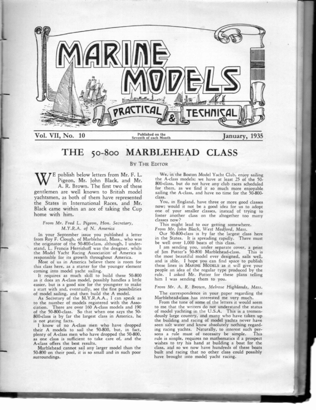
MARINE MODELS 257 2″ RAKE aa n~ HEADBOARD J $4 3 — 3 Dram. 3%” to DecR | FORE & MAIN HORSES 3″ wide NOTE LOCATE THIS MAST IN POSITION To START AND MOVE FORWARD OR AFT 1F NECESSARY FOR BEST BALANCE Sail Plan of “ Wampum II,” designed by James A. Potter (U.S.A.). The lines of this pretty little model are given in our Design Supplement, facing page 258.
258 MARINE THE FOUR-MASTED MODELS BARQUE “LAWHILL” By G. W. Munro HE accompanying plate shows the lines Freeboard «2.2.00… ..0.0e0u00s sft. 2in. Draught ………………… 22ft. 3in. Tonnage (gross) ……………… 2942 Tonnage (under deck) ……… 2696 Tonnage (net) …………..0..0.0. 2749 of the well-known barque “ Lawhill,” of Mariehamn, Finland. She is still a regular caller at our ports, taking part in the -annual grain race from Australia. She was built in 1892 by W. B. Thompson & Co., Dundee, for C. Barrie, of the same town. | believe she had her topgallant masts stepped in the normal way when she started her career, but had them stepped abaft the com- bined lower and top masts after a dismasting in 1904. This was done so that she could strike the topgallant masts very smartly before passing under Brooklyn Bridge. This does not give a very pleasing impression when seen from a distant side view, but it has proved very satisfactory from a sailing point of view. She was also arranged to carry oil in bulk. She is now one of the fleet of large four posters sailing under the flag of Gustav Eriksson, Before going on to describe the construction of the “ Lawhill,” I must first mention that it is entirely due to the kindness of the Managing Director of The Caledon Shipbuilding & Engineering Co., Ltd., successors to Messrs. W. B. Thompson & Co., Ltd., that I have been able to reproduce these drawings, which I have prepared specially for model making by including all the exterior details necessary for a very highly finished piece of work. I have also been very greatly assisted by some sixty photographs taken by one of our readers while the “ Lawhill’” was in London River last year. This reader also spent about a week taking very accurate measurements, which have been very useful in checking up any alterations and making it possible to include details not usual on a shipyard drawing. The subsequent plates will represent the vessel as she is at present. Now for the details of her construction : — The “Lawhill” is a steel four-masted barque with the following dimensions and tonnage : — Len gg… .cssessccsmens 317-4ft. 3 en eee 45-0ft. Westland lodav ack vc 2a-1ht. Moulded Depth ………… 26ft. lin. Length of: Poop ……..:… 42ft. Oin. Length of Bridge ……… 48ft. Oin. Length of Forecastle …… 33ft. Oin. The first four measurements are the factors which govern the scantlings of all the material used in the construction of the vessel. The advanced worker is fully aware of this, but the average model enthusiast is generally not too clear about the meaning of these terms, and so I may be excused for giving a few short definitions at this juncture. 1. The Length (L) is measured from the fore part of the stem to the after part of the stern post on beams. the range of the upper deck In vessels where the stem forms a cutwater the L is to be measured from the place where the upper deck beam line would intersect the fore edge of the stem if it were produced in the same direction as the part below the cutwater. 2. The Breadth (B) is the greatest moulded breadth of the vessel. 3. The Depth (D) is to be measured at the middle of the length, from the top of the keel to the top of the beam at the side of the upper deck. 4. A depth (d) is measured vertically at the middle of the length, from the top of the floor at the centre, or double bottom at the side, to the top of the lowest deck or tier of beams at the side. The scantlings of the various parts of the vessel are to be determined by numbers obtained as follows : — B+D=TRANSVERSE NUMBER. L x (B+ D)=LoncitupINAL NuMBER. If the vessel has a length of 134 depths (d) she is to have a bridge extending over the midship portion of the vessel. This is the reason why all the big grain ships have this erection, which is wrongly called a midship section by many seamen. It is a bridge purely and simply. The “ Lawhill” and her sister, the “ Garthpool,” were below these propottions, but they were built with this additional strengthening. We may next consider the lines of the hull and try to visualise what the shape is really like when seen in the solid.
MARINE The datum line is drawn horizontally and then divided into a number of sections, which added together represent the length L. Our design has ten sections with a sub-division at the ends. This is done so that the more iutricate curves at these positions may more easily be layed off accurately. The water-lines are spaced from the datum line, or bottom of the D, and are represented as so many feet from this line, viz., 1, 2, 4, 6, 8, 12, 16, 20 and 24 ft. respectively. These lines are very useful on the model, as they also represent the number of boards and their thicknesses for a laminated job. The buttocks are spaced from the centreline, and are similar to the water-lines. They are merely for fairing up and to give a better idea of the shape at the ends. In judging the shape from the lines, it must be borne in mind that, with the sub-divisions as shown, the fairness is not so apparent as it would be if all the lines were equally spaced. The innermost buttock is a half buttock, and if it is ignored, the bows will at once appear much finer on the sheer plan. Taking the lines generally, it will be seen that the hull is a fine one, while having a very large carrying capacity. Lloyd’s Rules have been compiled in a tabulated system which gives the scantlings for a vessel according to the Transverse and Longitudinal Numbers, those of the vessel falling between two given in the Tables. The **Lawhill’s”’ Longitudinal Number falls between 20500 and 22300. The Transverse Number falls between 69 and 72. The stem, stern and bar keel are regulated by the Longitudinal Number, and are as fol:— lows Bar keel, 104in. deep by 23in. thick; Stem, 94in. wide by 24in. thick; Stern, 94in. wide by 23in. thick. These pieces of steel form the backbone of the hull, and each must have the thickness of the shell plating added to it on the finished vessel, or model. The best method of constructing the hull is to employ the bread and butter, or laminated, system for the moulded shape of the hull, and then run a saw-cut along the centre line and slip in the stem, stern and bar keel. Additional width must be allowed for the amount fitted into the saw-cut. This is all very clearly explained in Dr. C. N. Longridge’s book, ‘“ The Cutty Sark,” and the modeller is strongly advised to follow it, MODELS 259 except for the outer shell, where there is a great difference in the texture of the material being represented. The “ Lawhill ” is of steel, and wooden planking will not give this impression on the model. The actual steel plates on a ship are about 4in. thick, and when this is scaled down for the model, a thin strip of thin drawing paper, or even a normal coat of paint, will account for this thickness. If drawing paper is used to represent the cold opaque surface of the steel plates, these must be glued on very securely with a good glue and allowed to dry thoroughly before colouring. I mention drawing paper, as this will allow lines to be drawn in Indian ink, where necessary. A perfect surface is the first consideration in any case, and this must be achieved before either paint or paper is applied. The actual plating will be explained in the next number when the plate giving the shape of the steel plating, together with the deck details, will be given. I do not advise the plating to be attempted on any model smaller than to a scale of sin. = Ift. The present drawings were done to 4in.= Ift., and have been reduced to 1 /32in. to fit the page. With so much reduction it is only natural that a slight distortion has crept in and curved the straight lines, and vice versa. This distortion is not sufficient to detract much from the value or accuracy of the published plans. Nevertheless the serious modeller should always obtain large scale drawings. In the present case these will shortly be on sale through the offices of this Magazine. (To be continued.)
260 MARINE THE MODELS YORKSHIRE KEEL (Concluded from page 235.) Sees are fitted to both leaches of the mainsail, the weather one being set up from the deck through a block on the forestay. The topsail sheets lead through sheaveholes in the main yardarms and thence through cheekblocks in the afterpart of the yard near the slings and so down to the deck. The mainyard is kept to the mast by a parrel, consisting of a string of hardwood beads about 2in. diameter. This is secured to the yard when it is in position for hoisting (i.e., square across the ship). As mentioned, the afterdeck had a wooden rail, but the foredeck has instead a 4in. iron rod, a wire rope or a bit of chain round it from the knightheads through stanchions, The sidelights and screens were put up aft on the wooden rail. There was a stove in the forecastle with a stove-pipe and also one in the after cabin. The keel whose plans we publish is an iron keel but with wooden rudder, tiller, windlass and hatches. The one illustrated in the photograph is a wooden keel and has a heavy rubbing streak all round, protected at bow and stern with half-round iron strips. Keels usually have white sails. The topsail yard has a sort of parrel round the fore top- CAVE REAK— STERN Showing Name, &e. on rail. ys a Sheet Roller “% at a§fer o§ Hatch. ae Wire| < end =—S 1 itWood or ral [eS rron Knee __¢ — Beam also Upper Beam i Iron Band .) <— about , 3b" 4 Keelson sie Side View Deraits of Mast LURCHET Not To SCALE. mast stay to keep it under control when lowering. If it is desired to reef the mainsail, it is lowered entirely and the earring secured round the yard, which is made extra long for the purpose. The yard is stowed fore-and-aft THORND YL on the deck. To set sail the mainsail, made up on its yard, is hoisted just far enough for it to be brought round and put square across the ship. It is then lowered and loosened and the parrel secured. After this it is hoisted, tack and sheet trimmed. To stay, the helm is put down and the sheet eased off. The forepart of the sail, which comes aback, blows her head off. The sheet is meanwhile pulled forward. The tack is then eased, the other tack pulled down and the sheet STERN showin 8 lee board roller in vail. trimmed. This is by no means an easy operation, but the keelman is an artist in handling his un- gainly vessel, while the rollers enable the gear to be manipulated speedily and easily.
MARINE The anchor is 3ft. 2in. across the flukes, with a stock between 5ft. and 6ft. long. The rail across the stern is almost invariably of wood, even in iron keels. It is a flat section 6in. wide by 24in. thick, but thicker across the actual stern on which name and port of registry are carved or painted. Prominent amongst the “ deck furniture ”’ of the keel are two huge “ stowers” (long poles with flattened double prong of iron, similar to a Norfolk wherryman’s quant), two long boathooks, any amount of bass warps, a heaving line, a ton or so of chain cable, and a water cask on chocks to starboard on the after-deck complete with dipper. The dimensions of the keel in our plans are 60ft. 3in. by 15ft. 3in., and she is what is known as a “ Sheffield size” vessel. We are indebted to Mr. Geo. F. Holmes for most of the information, sketches, etc., contained in this article; also to the Humber Yawl Club for permission to reproduce the lines given from their Year Book of 1901. We have also to thank Messrs. Clapson & Sons, Barton-on-Humber, who provided much detailed information, and the Curator of the Science Museum for the fine photograph of the keel model. 261 MODELS i leer MOePee FoRE Showing ENp of HATCH Mast Rotter (abt 3'6" lang by 3"dia.) and Tack Rollers(abt 19" or a" long by 3" dia) * iF fol— ————|| ou STERN OF WOODEN KEEL. *Sidelights & Screens carried on Rail at this point WELFARE p WOLTS EMILY (wood) & rE <0 ne ret (tTon) From a Sketch by Geo. F. Holmes
262 MARINE HOW TO MAKE STEAMER MODELS MODEL SHIP AND FITTINGS By A. P. Isarp, A.M.I.Mech.E. (Continued from page 244.) T the conclusion of my December article iw I was describing the manufacture of the group of boat fittings illustrated on page 244, and had just dealt with rowlocks. The use of a brass-coloured lacquer will hide a soldered joint, provided the jojnt has been well and carefully soldered. Rowlocks are not kept in their sockets when the boat is not in use, but should be taken out and dropped into the bottom of the boat, the tyer previously mentioned should be long enough to allow them to hang down inside the boat. (b) Boathooks are of great variety, the one shown is a very useful and convenient type, but is not easy to make; the same remark applies made before in connection with rowlocks, it will be an ornament only, and therefore need not be of great strength. Turn up a heavy piece of wire to the correct taper in the lathe, but turn with the - taper towards the chuck, leaving the bigi end for centring and drilling out to take the wooden shaft which may be merely a tight push fit. The hook is simply a piece of bent brass wire soldered into ‘position rather heavily, and afterwards filed to shape. If a strong job is required it would be better to saw and file from the solid. (c) A hand bailer, simply press out the bowl from light brass and solder a ring nicely round the top, turn up a wooden handle, or, as it is so small, it may be carved with an ordinary pocket knife and finished off with glass paper; make a little ferrule from a tiny piece of brass tubing and fit the handle to this; file the end of the ferrule to the shape of the curve of the bowl, and touch with a very hot soldering iron. The handle looks nice if made from teak, into which linseed oil has been rubbed. (d) Bow Plates. This fitting is not absolutely necessary, but if your model is of a smart yacht, or similar craft, then it is usual for her dinghy to carry her club. or owner’s colours. The modeller will have to be a bit of an artist for this job; it can be painted direct on to each bow of the boat, or it can be a very magnificent electrotype of copper. The modeller might try this method which, if carefully done, will produce exactly the same design in any number of places. First make an indian ink tracing of the design, when finished turn over on its face and blacklead or chalk over the back; now place the tracing, right face outwards, on one bow of the little boat, and go over the tracing with a fine blunt pointed piece of bone; remove tracing and there should be an outline perfect in detail for you to paint and colour. The tracing can be used over and over again. Of course, the work will be very minute, but it will repay the trouble and enhance the appearance of the ship’s boat. (e) A Screw-down Boat’s Plug. This is located at any convenient place at the boat's bottom, and consists of two parts: one the screw plug, and the other the screwed socket for same. The screw plug should be made last, in order that the thread will fit the socket nicely; it can be turned up from a short piece of round brass rod, but before being cut off to length, the finger piece should be filed to shape. Notice carefully that there is a small slot cut in the side of the screwed portion of the plug, for about three-quarters of its length. The object of this is that by partly unscrewing the plug will afford a passage for water to escape or enter the boat; a leather washer is interposed between the plug and the socket, so that when screwed down it will be water- tight. The socket should be piece of round brass rod, the holding-down wood flange are drilled after turned up from a drilled and tapped; screw holes in its removal from the lathe. Some boats merely have a hole into which a wooden or cork bung is pushed, and a great many have no provision at all; never-
theless, it is correct that they should have. (f) Boat Cover Buttons. These are for fixing the covers to; the covers are of canvas, and are for the purpose of keeping the boat clean and dry. . They are fitted at equal intervals outside along the gunwale, a few inches down and, if a really good job is required, they should be clenched over rooves. They are easily turned up in the lathe from stout brass wire. (g) Sea-going Oars. Select the best straightgrain spruce in your stock, and cut into strips rather larger than the overall size of oar required, and a good 50 per cent. longer; chuck in lathe and turn shaft completely to size and shape; remove from lathe and finish off blade by carving. It is quite an easy job, although several may be broken in the attempt. Use good waterproof glue and stick on the leathers, which may be cut from an old pair of kid gloves, the copper binding band at end of blade may be painted on with bronze metallic paint. a The blades are straight as it is not usual for spoon blades to be used for sea work. The oars should be bright varnished and unpainted. Gaff Jaws (Fig. 73). trated. . Two types are illus- MODELS 263 (a) Wooden jaws are used mostly in mode- rate-sized sailing boats; they are for the purpose of preventing the gaff from slippin g from the mast by means of what is known as the parrel, which is a line with a string of wooden beads, which passes round the mast from one arm of the jaws to the other, as shown in the sketch. They must be carefully carved out and the gaff spliced, as shown, then clenc hed or riveted over rooves; the rivets being either of copper or yellow metal. o make a strong job the gaff and jaws should be glued with waterproof glue in addition. (b) Metal jaws are generally better than those of wood, since considerably less thickness of material is required to obtain the same strength and, in addition, the halliards are not so liable to get jammed between the mast and the gaff jaws; the jaws should be leather covered and, if kept soft with oil or grease, will not squeak. Some metal jaws are fixed rigidl y to the gaff; the type illustrated is fitted with lugs and bolt, thus forming a hinge—this allows the gaff jaws to fit the mast when the gaff is at any angle. By glancing at the sketch the large bearing surface will at once be notice d, when compared with that of the wooden type. The construction is simple. Cut out and bend to shape the jaws from sheet brass (real ones are, of course, made from galvanized iron or steel); next cut out and bend the two lugs, and rivet these to the jaws in the positio ns shown; cut out and bend the gaff housin g lugs and, as before, clench over rooves to fix. Now drill bolt hole, and fit bolt, but not too tightly; allow the hinge to work quite easily. In order to get the bolt tight without binding the gaff, and to prevent the movement of the gaff working the nut loose, simply cut the thread on the bolt just short so that the ae | Oa a nut can be screwed up tightly without pinch- Ser — MARINE ing the lugs. The jaw may be leathered, but it would not be necessary for practical purposes in a model. Gammon Iron (Fig. 74). The bowsprit may pass through either wooden bits on the deck, or it may be fitted with a heel socket, it then passes through an iron hoop, which may be leather covered; this hoop is bolted on to the stem.
264 MARINE Sometimes this gammon iron is plain, but it may embody rollers revolving in forks— perhaps only one, or maybe two: one on the port and the other on the starboard side of the stem, as shown in the sketch; these rollers are used for the anchor cable, hawser or warp. MODELS Make and fix the eye in the head of the iron and note that it is turned in line with the ship’s centre line. The gammon iron may be painted aluminium to represent galvanized iron work, but it is usual to paint the legs down the stem the colour of the hull’s topsides. The eye at the top of the gammon iron (To be continued.) is for a stay to the masthead, sometimes used as a runner for a jib. Note that when the bowsprit is run inboard it is kept in place by a bolt which is called A CANADIAN A-CLASS MODEL Cc the Fid. FAG. 74. To make the gammon iron, first cut out and bend to correct shape over the actual stem of the model; now take a piece of scrap steel and file to the exact thickness of the stem, and slip the gammon iron over it; this piece of steel must be long enough to be held tightly in the vyce. After cutting out, bending and making the roller lugs, sweat these into place one at a time and, before attempting to solder the second into position, drill a tiny hole in the first, and put a rivet through; to put this rivet in, slip the gammon iron over the piece of steel in your vyce, and use it as an anvil. The first lug being soldered and riveted in position, the second may be proceeded with without any fear of unsoldering the first. Now drill the holes through the lugs and iron for the roller pin; turn up the rollers and bore them to suit the pin; slip pin through lugs, rollers and iron, securing the two ends with nuts, as shown. When fitting the gammon iron a hole must be bored through the stem for the roller pin to pass through. cd MAB ” (ARTHUR M. BRYDON, TORONTO) See letter in Correspondence Columns. The principal dimensions are L.O.A. 73ins L.W.L..: 30m. Displacement 434lb. She is here sailing on Lake Kashishomogobog, Muskoka.
MARINE MODELS 265 SHEET LEADS FOR MODERN SAILS ANON. HE modern sailplan with its high aspect 4 ratio requires somewhat different sheet leads to the lower plans in vogue until recently. For instance, the proper lead for a boomless jib was to halve the angle of the clew. The modern jib, however, is higher and narrower, with the result that one requires more pull downward to keep the leach from winding, and less on the foot. Hence we have the double-clewed jib, which has become famous in the America Cup Races. In models it is customary to use a footstick (or club) on the jib in order to get automatic action to windward. I am aware that this is effective from this point of view, but | question whether it does not impair the efficiency of the sail as regards its propellant force. It is certain that it converts a jib from a lifting sail into a depressing sail. Practical experiment on a full-sized boat proved that the boom jib, as we know it, depressed the boat’s head and made her hard to steer, but with an ordinary loose-footed jib this effect was removed. Further experiment with a radial jib proved that the radial jib had both the advantages of a loose-footed jib and a boom jib. As some of my readers may not be familiar with the radial jib, I will describe it. The clew of the sail is extended by a boom, to which it is made fast. The boom, instead of going straight along the foot of the sail, has its heel in a socket (or gooseneck) on the deck (or bowsprit) a short distance aft of the tackhook of the actual sail. The action of the device is that as the sail is checked out the boom, being shorter than the foot of the sail, has a shorter radius and, consequently, gives the sail more flowand belly as it is eased off. As the sheet is brought inboard, the converse takes place, and the length of the boom is arranged so that the foot is almost A single doubleflat when close-hauled. ended sheet is used, one end being made fast to an eyebolt in the deck and the other leading through a corresponding eyebolt on the other side of the ship and having bowsie adjustment. This arrangement has been tried Moreover, the and found most efficient. double sheet has a greater downpull than a single sheet working on a horse, which is abolished. The main disadvantage is that in gyeing different adjustment of sheet cannot be made for the two tacks by means of the However, if the skipper is using jockey. rudder gyeing this makes no difference. I see no great difficulty in devising some sort of double sheet arrangement somewhat similar to the double-clewed jib referred to above. It is customary to extend the leach of the jib slightly aft of the mast on the roach, using battens, but this should clear if the second sheet is properly arranged. I think the second sheet should be about twothirds of the way up the leach of the sail, but experiment might decide otherwise. The way I should rig this would be from a screweye in one side of the mast through an eyelet in the sail and back to a screweye on the other side of the mast, adjusting with a bowsie tail down the side of the mast. The adjustment would not require to be as fine as that for the foot, as the purpose of this second sheet is to keep the clew inboard sufficiently to obviate winding of the sail. Hence it would not require readjustment if the jib needed re-trimming in the course of a board. I have heard it argued that a radial jib This is prevents the use of jib steering. incorrect, as it can easily be fitted. An eye is screwed into the underside of the boom about an inch or so forward of the sheet lead (which, by the way, should be right at the after end of the boom). The jib steering lines have a hook, which is put into the eye when required. Adjustment is required separately for the steering lines unless arrangement is made along the underside of the boom for a jackline and bowsie, taking the two lines in the manner usually employed for the steering on the mainboom. Passing from the jib to the mainsail, here, again, the old method of using a single sheet to a horse is not always satisfactory, as the sail tends to wind and the after-leach spills with consequent loss of driving power. The best method is to use a double-ended beating sheet similar to that described for the jib. The mainsail in a high, narrow rig is particularly prone to spill when gyeing, with the result that the boat bolts. This is one reason
266 MARINE why an ordinary rubber gye is unsatisfactory in a boat with an ultra-short boom, but. there is another. The shortness of the boom often causes the builder to place his screweye for the forward end of the gye forward of the centre of gravity of the boat. As the C.G. is also the centre of gyration of the boat, the gye must be aft of it to be sure of pulling the stern up to windward. Generally speaking, however, it is best to use a rudder gye with a short boom. The best way to rig this is to put one screweye aft of the boom end. The gye leads thence to an eye in the extreme end of the boom and back to a second screweye considerably more forward, and then to the quadrant. The part next the after eye is of rubber for about two-thirds of the distance to the boom, and the part next the quadrant contains the bowsie adjustment. In order to get the best results from a rudder gye either a double-tension slide or a pinrack should be used. The latter is such a useful fitment under all circumstances that I have never been able to see why it was abandoned on the invention of tension slides. Tension slides are most useful for effecting a retrim, but for many other purposes they do not take the place of the pinrack. The only other sheet lead for the working sails is that of the running lines. The further forward these are attached to the boom, the greater is their leverage on the steering gear. If they are too far forward this will give them too much power and make for a jerky action consequent on a hard pull and tight tension. Moreover, the boom will be more easily lifted by the sail when reaching. In considering the angle at which to trim the sail it must be remembered that the upper part goes off more than the foot. If the foot is at its most effective angle, the upper part will be losing part of its drive. In hard winds, when this is most apparent, it is better to keep the foot a little closer inboard and thus effect a compromise. In a hard wind, therefore, from every point of view it needs the point of attachment for the running lines further aft than in a light wind as, in the latter, not only do we want as much pull as we can get, but also to let the sail take a good flow when reaching or running. It is impossible to exactly prescribe the exact position for every boat, and the skipper must be ready to experiment, but I should suggest as a preliminary trial about one-third MODELS of the length of the boom, from its after end. I think it may be found advisable to have two positions, one for heavy and normal winds, the other for light winds and trivial breezes. Recently we have heard a lot about tacking to leeward. When I first sailed a model, [ used to find it difficult to get the exact adjustment of the Braine gear when running, patticularly in paltry, rather variable winds. I found that by sailing gybe and gybe, with slightly too much helm, I got straight down the pond and, though I covered more ground than my opponents, I often beat them by sheer speed. I was reproved by the old members for bad sailing, and told I was lucky when I won. Yet it would now appear that I was merely ahead of the times, and actually tacking to leeward, and being really scien- tific! It certainly did not pay when there was weight in the wind and everything, including spinnakers drawing, but I am not so sure about light winds when a spinnaker is deadly if one gets to leeward of the course. On the other hand there is a little stunt for spinnakers that is useful in light weather. Set up the boom with a topping lift and fix the gyes to stay put without the spinnaker. Then make fast head and tack with a single thread of cotton. Likewise use a thread of cotton for a sheet. If you get to leeward and the boat wants a retrim, one pull removes the spinnaker, and off she goes merrily! SLIPPING MAST FITTINGS OTHING is more annoying than a gooseneck N that is slack on a mast and tends to slip. This can be easily remedied by putting one or more turns of adhesive medical plaster round the mast, under the fitting. At a pinch, insulating tape can be used, but the adhesive plaster is cleaner. Speaking of insulating tape, we recollect one of the competitors in the A-class Championship at Gosport, some years ago, let his boat fall, with the result that the stern was badly cracked along one of the joints in the hull. Most people would have retired at this point, but not that skipper. He raided a car toolbox and procured a roll of insulation tape. With this he bound the whole counter of the boat round and round, and not only managed to finish the race, but gained quite a respectable position. Another use of insulating tape or medical plaster is the temporary repair of a broken hollow mast or spar. A suitable liner is put in and the whole bound together. Joe Weaver, of the U.S.A., finished one of the international races with an ordinary lead pencil as a liner for his broken mast.
MARINE MODELS 267 * f,3 2 = a oe cj ERS So PETAR i Si TN a, eA 54 goed “fs ¥g § "2 ¢ a fi2 y ae a :5 > $ 6 n BY va a 3 “4 – Ve) oe “ Fem Le Ks -, Se 2 oe ~ 2 : S? J 7 t= SS : a) ot Sy Pa as . oe Sey v4 Uaely lace f RY gé> i F (Continued from page 238.) B’ a curious coincidence both my col- league who writes on Petrol Engine and Hydroplane Topics, and I myself, last month, touched upon the subject of engine bearers. Just a week before the December number of this Magazine appeared the Motor Boat had an article on “ How to Fit Engine Bearers.” Although this was intended for full-scale motor boats, I cannot forbear to quote one paragraph as it so admirably expresses the work engine bearers have to do. There are certain matters to bear in mind in fitting engine bearers. One is that strength and rigidity are necessary. The strength required depends on the power and weight of the engine to be bedded on the bearers. To have them too stout is a good fault. As to rigidity, there is no degree. Rigid 1s ngid, and this they must be. It is well to remember that engine bearers are not for the motor to rest upon. The engine only does that when it is not in action. When it is in action, the bearers are to hold down the engine. Thus, they must be well fastened down to the botiom of the boat. A very good example of how plant should be installed in a prototype model is “ Valkyria,”’ a fine model liner built by her owner, Mr. W. Thornton Parry, chairman, West London M.P.B.C. This fine vessel is well worth a detailed description, as she embodies many points of interest. Naturally her owner has great experience in these matters as he has been model power boating since before the War, when he was connected with the old Kensington Club. During this period Mr. Thornton Parry has more or less specialised in this type of craft, and every feature is the result of practical experience. The Round Pond, Kensington, is a big water where boats have at times to stand a lot of rough weather and broken water. Moreover, there are often many craft afloat. Consequently all detail work has to be robust and sturdy, and the boat herself seaworthy. The type represented is an intermediate Cunarder, but no actual prototype was followed. The size is 72in. by 103in. beam. The depth of hull to maindeck is 74in., and the draught 5in. The hull is yellow pine, built bread and butter fashion. The layers are 3in. thick and put together with white lead and goldsize, and screwed with brass screws. She is well painted inside for protection. The keel and stem are in one piece, being made of steel and let into the hull. She is fitted with anti-rolling keels. The lines are graceful and true to the prototype. The upper works are of tinplate, and comprise A, B, C and D decks, the actual decks being of wood. From forward the deckwork consists of forecastle, anchor davit, electrictype anchor windlass, handling the two cables, which are led properly through the hawse pipes, and go below through chainpipes. The anchors are Byers type, and more will be said of these later. Aft of the forecastle is a short well deck, and aft of this is B deck, which is level with the forecastle. On this deck is the baggage hatch, which is removable, and gives access to the blowlamp and running controls. Actually the whole superstructure lifts off, but whilst running it is only necessary to remove this hatch. In the photograph of the boat, it will be noticed that Mr. Parry’s assistant has the hatch off, and is obviously doing something in the engineroom, whilst the Captain appears to be attending to the wireless aerial. The first-class passenger accommodation takes up the centre of the ship. The bridge carries a wheelhouse, standard compass, telegraphs, etc. The after deck has a large deck-
268 MARINE MODELS MR. W. THORNTON PARRY (left) WITH HIS MODEL LINER “ VALKYRIA ” house with an after bridge carrying a docking telegraph. Ten lifeboats in all are carried in davits. Eight amidships and two on the after deckhouse. Other deck fittings comprise fairleads, bollards, hawser reels, etc. The wireless room is on the upper deck between the funnels. No attempt is made to embody every fitting found on the prototype, the general effect is what is aimed at. Sufficient fittings are given, and these are well made and immensely strong, so that the whole boat gives a most pleasing representation of the ship under way. I have omitted to mention that there is another hatch on the after deck which gives Before leaving the access to the container. decks for the plant, mention must be made of the funnels, ventilators and system of the mouth of the ventilators, and mounted on stems made from Zin. radiator tube. A hole is drilled through so that these actually ventilate. Further ventilation is obtained through the deckhouses. The portholes along the vessel’s side call for comment also. These are made from the little brass cups into which screw heads are sunk in These are fixed in high-class coachwork. position with waterproof cement, and hold admirably. The anchors are cast by a method used by Mr. Savage, and the flukes move. The flukes are aluminium. The method used is known to dentists as the cire perdue (lost wax). A plaster mould is first made from a pattern which can, if necessary, be made from wood. This mould is in two halves. Get some The result of this arrangement is that the dental wax, which can be obtained from any dental stores. This is warmed up until sufficiently soft to mould easily with the fingers. Put a suitable quantity into the mould and press the. two halves together. The wax model is removed as soon as set. If a number of any fitting is required, more wax models dustcover from old type motor tyres. These are cut off, annealed and belled out to form The next step is to procure some of the moulding material used by dentists for taking castings. This is a special mixture that stands higher temperatures than would be possible ventilation. Of the two funnels one is a dummy. The business one consists of the inner funnel, which is attached to a smoke box and does not touch the superstructure. Outside this is a double funnel attached to the superstructure. paint never burns or scorches. The ventilators can be seen in the photograph. These are constructed from the outer are made.
MARINE with plaster. In passing, it may be mentioned that the original plaster mould can with advantage be made in Ash’s dental plaster, as this gives a better surface than ordinary plaster of Paris. It may be added that when extraordinarily fine castings are required there is a fine dusting composition in powder form that can be obtained. By using this in addition it is possible for an expert to make a casting from a bee of such a fine nature that the veins of the wings are clearly visible This, however, is not required for model work. Turn up a dome-shaped piece of wood or metal. Of course you may have something in the scrap box that may serve the purpose. I recently used the protector from the nosecap of a shell—a wartime relic—but this will give an idea of the shape required. At the tip drill a hole for the “‘sprue’’ pin, which should be a good fit. Now the sprue pin is a little piece of wire on which the wax model is mounted. A gramophone needle answers admirably for a small casting. Place the dome with the sprue pin on a piece of flat tin. Warm the pin slightly so that it will penetrate the wax and mount the wax model on the pin, putting it sufficiently far on to hold firmly. Find a piece of old iron tube of a sufficient size to go over the model, leaving about 4in. margin all round. The moulding material as supplied is mixed like plaster of Paris to the consistency of cream, and poured round the model. Care must be taken to get it well under the model and eliminate any air bubbles or pockets. It is then put aside to harden. When dry, turn upside down and take off the tin and dome. Pull out the sprue pin with pliers, if necessary. You now have the final mould. Where the dome was is the funnel and the sprue pin has left the pouring hole through which the metal is got into the mould. At the moment, of course, the mould is filled by the wax model, so the next step is to invert the mould and melt the wax out. This is a lengthy process, and decidedly smelly. The mould can be packed up with. coke to conserve the heat, and the blowlamp played on to it. When it is all clear you will be able to look down the sprue hole and see the inside glowing red. If you are using aluminium it should not be more than a glowing red. Place sufficient aluminium in the cup and play the blowlamp on it for a few minutes until it melts. Clean off any dross and coax it with a piece of wire. MODELS 269 This will not make enough run in to make the casting, but will give matters a start. Although it has not been mentioned until this point, a pad should have been prepared for the next step. This pad is made up of pieces of asbestos cardboard or string, which are soaked and rendered pulpy and made up into a pad. This pad should be damp when used. When the metal has reached the state described the pad is clapped firmly over the funnel hole. Steam is generated and this forces the molten metal right down into the casting. This method requires a little practice, but once mastered gives very perfect results. When cold, the mould is broken up and the casting cleaned up. If any dentists or dental mechanics read this article, I ask their pardon for not using the proper technical terms throughout my description, but my desire is to instruct those who are not acquainted with this terminology. The fact that any number of wax models can be produced enables this method to be used for making any required number of duplicates of a fitting without making more than one original pattern. On the other hand this method takes a considerable time and, where a number of castings are wanted, it may be better to take the pattern along to the foundry if one is known where small work is handled satisfactorily. Having digressed to explain this method of casting, I fear I have filled up my allotted space this month without touching on “ Valkyria’s “ innards.”” The main characteristic of her steam plant is its reliability and extreme cleanliness in operation. It is in fact a good solid job, eminently suitable for its work. I will describe this at length next month. The cire perdue method of casting, which I have described, is, however, well worth mastering, as so many small fittings can be made this way, and should be useful to sailing ship modellers as well as the steamboat fraternity. (To be continued.)
270 MARINE MODELS PETROL ENGINE and HYDROPLANE TOPICS By J. B. INNOCENT (Continued from page 240.) O continue with the drive shaft and the bits belonging thereto we now come to that interesting problem, the universal joint. As most of you know, it is usual to set the tail shaft at a much lower angle than the drive shaft, whence the need for the universal. The actual angle depends on the relative lifts and loadings of the planes, and must be arrived at by experiment. That much can be done by this lowering of the thrust line is indisputable for hulls fitted with straight through drives have been transformed into quite docile craft, whereas they were unmanageable in their original form. One of my correspondents who has had much trouble with diving boats, has never fitted a universal skeg because he was not satisfied with his engine universal. This is, of course, most unfortunate as he will probably find that at least one of his unsuccessful hulls will behave in an exemplary manner if he makes the change. UNIVERSAL COUPLING E = 1) _X SKEG SHAFT AND HOUSING As to which is the best type of universal for our job I cannot be dogmatic, for, whilst we use the square ball type, both M. Suzor and Mr. Clifford prefer the crosspin and slotted ball, and seem to get no trouble, though M. Suzor’s is positively minute. Like most things, it is not the designs that are faulty, but the-excellence or otherwise of the work put into them. I am appending a sketch of our own joints, drawn to actual size, and for soldering to the shafts. Our methods of generating the bits are quite simple, no special cutters are used, nor do we have to stick bits together. The procedure is as follows—chuck a piece of mild steel, centre drill and drill out for the tailshaft so that the shaft is a free push fit for the depth shown—turn the outside taper the same length as the hole and cut in to form the neck—then turn a ball-end as accurately as you can, finishing to profile with a file, and cut off. The diameter of the ball should be a few thou., say five, under the diagonal measurements of the square required. The ball is now filed square with the aid of a micrometer, keeping an eye on the line left between the faces, to see it does not vary in width. The female half is made by drilling a piece of mild steel to take the drive shaft, plus the depth of the square, and turning it down to the diameter required, but leaving it parallel for the time being. The square, which is just full of 3/16in. across the face, is then cut out with a drift and diamond chisel, after soldering a piece of shaft in temporarily to protect the hole. The drift is started with the chisel and then they are used alternately until the requisite depth of hole is obtained. You must, of course, make your own drift, filing it up from silver steel to micrometer. The job is, of course, held in the vice by the unfinished part, whilst all this hammering is on. Next, case-harden the working faces to a depth of a few thou., clean and tin the holes and fit the female to a piece of shaft, and turn the taper; if you have case-hardened this bit and cannot get under the skin, start on the grind- ri going stone. Many people get trouble with case-hardening, and come to the conclusion that the stuff they are using is no good, but the trouble usually lies in the heat applied, or the steel, providing a good commercial compound is employed. For open hardening I use “ Kasenit No. 1,’”’ or cyanide, and for box-hardening ‘“Kasenit Durapid.”. The Durapid is really
_ MARINE wonderful stuff, and goes in at a remarkable rate. Remember that the steel must be over 800° cent., which is well past ordinary hardening heat. For small box-hardening tins are quite good enough, as you can keep them at $00° for half an hour before they burn through. No luting is necessary for our work, but if Durapid is used the work should be packed in powdered charcoal, which helps to even up the heat and exclude air. So far as I know, powdered charcoal cannot be bought, so | put rough stick stuff through the domestic mincer. If you follow suit, beware of the powers that be, for, although you are unlikely to harm the mincer, people are apt to be prejudiced. After the casing, the bits should be allowed to cool in the box, heated up to bright red, quenched, then heated again to full red and quenched; or, if open-hardened, quench from the hardening, heat up and quench again. This double quenching is not essential, but as it prevents any tendency to scaling of the case it is worth while doing. The tail shaft we always make larger than the drive shaft, as shown. The whole shaft is turned from a piece of 3in. steel, the boss being solid and the dog made by slotting the boss with a saw and file, and soldering in pieces of 1/16th cold rolled mild. This shaft runs in a steel housing, fitted with bronze bushes, but a bronze housing is just as good provided it is undercut in the centre to permit of oiling. Should you use any red bronze bushes do not try to fit them very close, as it is the devil itself for seizing. The thrust bearing on the skeg is made from two case-hardened steel washers with a groove turned in them. They must, of course, be turned from the solid, and if both a round nose tool and a parting tool can be set up together in the tool rest, they can be made so quickly that it is worth making a few extra for stock. The balls themselves should be 1/16in. stainless steel, now they are making them truly spherical, but ordinary balls will give no trouble provided they are oiled after each run. The skeg itself should be made of steel plate brazed or silver-soldered to the top fixing plate and to the tail shaft housing. The “‘Bean”’ did all its running on a skeg made up of brass and solder, but I do not recommend it. It is, of course, necessary that the blade should not disturb the water more than is essential, and to this end must be filed up to a respectable streamline. There does not, however, appear MODELS 271 to be any advantage in keeping the section under 3/32in., and 1/16in. skegs, like our own, are very prone to whipping. In the past it has been common practice to fit the skeg at a slight angle to act as a rudder, either with the idea of helping the boat round or of holding out the line, but neither idea seems to do more than make the boat unstable. The cure for the former trouble is to move the line forward, and for the latter to find a bit more power. WITH THE POWERBOAT CLUBS WICKSTEED M.Y. & P.B.C. _ It is only two years since this vigorous Club was inaugurated, and its first Club Dinner, Social and Exhibition was held at the Royal Hotel, Kettering, on November 21. This was attended by large numbers of members and friends, including visitors from Leicester, Bed- ford and Irthlingborough. very enjoyable, and several The evening proved prominent local artists combined to give a concert of a very high standard. Powerboats, yachts and aeroplanes belonging to members were on view, and revealed excellent craftsmanship. Mr. H. R. Perkins, the Club’s genial Chairman, proposed the toast of the Wicksteed Trust. He said that the Club owed its existence to the Trust as the Trustees had wholeheartedly supported it, and placed no restrictions on the use of the water. With such generous backing the Club should speedily become one of the finest in the country. In his thanks he coupled with the toast the names of Mr. Tom Wallis, a Trustee, and Mr. A. C. Neale, Managing Trustee. In replying, Mr. Wallis said that the Trustees were anxious to support clean, healthy sport, and were always open to receive suggestions. Mr. Neale also replied. The toast of the Wicksteed M.Y. & P.B.C. was moved by Mr. Evans, a visitor, who congratulated the Club on its rapid progress. Mr. L. S. Axe, Joint Hon. Secretary, replied for the Club, and said that it was very gratifying to the officials that in little under two years the Club and risen to a foremost position amongst model yacht and power-boat clubs. Naturally the Committee have had their difficulties, but these have been surmounted. The success of individual members of the Club has been very creditable, particularly Mr. Harry Robinson, with his boat ‘* Chic.’’ The Committee now have the development of the Junior Section under consideration, and measures to that end will be taken in the near future. Mr. Axe urged members to use their spare time in building boats. ‘* Your spare time,’’ he said, “‘ is the acid test of character. It holds the success of your dreams.’’ He hoped that one dream would be to see the International Trophy amongst the Club’s captures during the coming season. The toast of the visitors was proposed by the Vice-Chairman, Mr. H. Maycock, and_ suitably responded to by Mr. T. Whitworth, of Bedford.
272 MARINE = & =: MODELS =, oe oon . NC “Ny z \) SN ¢ . as TR ag Zoe “8 jj “ re. uy 4 Wa ot “] a“ \ | * ms : aaa! H . =e Tae S er — ee B. a: ae. o- @-—w’* — — ~, ‘ahs NORTH OF ENGLAND BRADFORD M.Y.C. The last flag race of the season preceded the annual meeting on December 8, at the ‘* Stone Trough Inn,’’ Rawdon, Nr. Leeds. The proceedings at the ‘* Inn ’’ commenced with a ** high-tea,’’ graced by our two lady members; then the annual meeting, presided over by our Commo- dore, Mr. F. C. Hirst. This included the presentation, by Mrs. G. E. Snow and Miss Marjorie Smith, of the ‘* Atkinson ’’ A-class Trophy, and the prizes for the best average over the season for the fortWinners were as follows:— nightly flag races. ** Atkinson ’’ Trophy A-class—‘* Defiance ’’ (C. D. Wilson, sailed by Geoffrey Kitchen, on October Map Races, A-class—*‘ Juno ’’ (Geo. E. Snow). 14). 6-metre—‘ Challenge ’’ (E. North). 10-raters—‘‘ Thurne “’ (J. P. Clapham). The following officers were elected for the season, November 30, 1934-5:—President, Major Butler; Vice-Presidents, Vernon Dawson, Esq., Admiral Turner, Cutliffe Hyne, Esq., and E. Gill, Esq.; Commodore, Frank C. Hirst; Vice-Commodore, E. North; Treasurer, B. E. Garbutt; Secretary, i Oe Crowther (Post Office House, Leeds); Racing Secretaries, Wilfred Roberts and H. Atkinson; Club Measurers, J. Whittaker and W. Dewhirst. The Treasurer’s report showed a balance on the right side. Several new members have been elected and are in prospect, with the result that we are _ having to increase the size of the boat-house. The meeting terminated by Mr. F. C. Hirst, with the cine-films showing the A-class National and International 1934 races, together with several London and local films. foP —— ————— —a >< House, Derby. That boat was a failure, and he nearly lost his life experimenting with it in a graving dock at Hull. From that time Mr. Colman Green said that he became ‘* model minded and decided that there were two things worth while in this world—one was to preach model yachting, and the other to agitate for proper model yacht ponds.”’ Mr. Green mentioned that he originated the idea of building ponds with a retaining wall, and the first illustration of such a pond appeared in the Norwich Mercury about 1907 or 1908. Great Yarmouth built one of these ponds almost immediately after, but it was not until several years later that Norwich constructed a ‘* built-up ’’ pond. In these days of bituminous substances and materials this idea is becoming increasingly popular. Using a small model schooner, built to fit an attaché case, Mr. Green explained the points of sailing. Many questions were put to the speaker, who drew diagrams on the blackboard to elucidate his points. On the following Saturday a small party of the boys visited Wanstead for practical instruction. Thirty years have elapsed since Mr. Green made his first model, and during that time he has formed several model yacht clubs. He has, however, taken particular interest in the Junior Section of our sport, and is now one of the veteran organisers of model yachting for the boys. We hope that teachers in various parts of the country who are model yachtsmen will undertake similar work as the future of model yachting lies with the rising generation. Y.M. 6-m. O.A. The Club held its Annual General Meeting in the Clubhouse, on December 16, with the Club’s Chairman (Mr. C. Adams) in charge. After the usual routine business, the Chairman presented his report of the season’s doings. Mr. Adams commenced by referring to the sad LONDON & DISTRICT FINSBURY PARK JUNIOR SCHOOL With the approval of the Headmaster, Mr. Colman Green addressed a large number of the boys on November 19, on Drawing, Shaping and Sailing Model Yachts. About twenty youngsters brought up a miscellaneous collection of craft and as far as possible these were used for discussion. Mr. Colman Green mentioned that the first model he made was in 1904, when staying at St. Michael’s death of Mr. E. E. Marshall. He then proceeded to summarise the Club’s performances in the British A-class Championship and other open events. From this he passed to events held on the Club’s homewater. He then referred to the Club’s measuring apparatus and thanked Mr. Corby for constructing this. The films of 1933 and 1934 Fleetwood Regatta were due to Mr. G. Howard Nash. He concluded by defining the exact position of the Y.M. Cup Committee. : After election, the Officers and Committee remain as before, with the addition of Lt.-Col. W. C. Holden and Mr. H. C. Whetstone, who were elected to the Committee. During the meeting Mrs. J. Essam Lee kindly presented the Nairn Cup and prizes to the winners.
MARINE The Club held a very successful Supper at Anderton’s Hotel, London, E.C., on December 18, the chair being taken by Major M. Heckstall Smith. After supper, the Chairman proposed the health of the Club, coupling with it the name of the Hon. Secretary, Mr. J. G. Feltwell. In his reply, Mr. Feltwell traced the growth of the Club, and referred to the generosity of the President, Mr. T. B. Davis, owner of the schooner ‘‘ Westward,”’ in presenting 273 MODELS Oor, the Club with its handsome Club House. In calling upon Mr. C. Adams to propose the health of the guests, the Chairman spoke of Admiral Turner’s most valuable research work in the science of yacht designing. Mr. Adams then briefly proposed the health of the guests, coupled with the name of Admiral Turner. Admiral Turner then replied for the guests, and thanked the Club for their hospitality. He then referred to his school days, when he had the advantage of being under the late Albert Strange, of the Humber Yawl Club. He first came into serious model yachting in the early days of the 18-footers. One learned more from failure than success, and his first boat was a complete failure. His second boat was ‘‘ Musketeer,’’ and in her design he noticed that the metacentre was in a line as far as her forward sections were concerned, and thus commenced to discover the secret of the M.C. shelf. This boat was a great improvement, but still showed lack of balance. The late Mr. George Hemming then suggested that he should arrange that the centre of buoyancy did not move in a fore and aft direction From this point, the when the vessel heeled. Admiral found that he could design balanced ‘boats. Continuing, the Admiral said that buoyancy is the It therefore greatest force exercised on a boat. appears logical to place this big force under control, and not worry much about minor considerations. Both sides of the vessel must be alike when heeled. It is, of course, impossible to get them actually alike in shape, as the keel must be taken into consideration and treated as part of the hull. There is nothing mysterious about the M.C., which is simply a spot on the centre line of the boat, and all it means is that the boat must be balanced evenly about this. The C.E. and-C.L.R., though easily ascertainable geometrically, are in reality nonexistent and have no effect on steering. Shapes of profiles have nothing to do with the M.C. system, though they certainly have a big effect on the steering of heeled boats. In conclusion, he referred to the relationship between models and prototypes, and said that subject to certain common-sense modifications, model yachting and yacht practice in designing agree in their entirety. The Chairman then called upon his brother, Col. S. Heckstall Smith, to address the members. He started by saying that model yachtsmen as a whole were far more knowledgeable than yachtsmen, as they knew more about their boats’ designs and proper set of Sails. He encouraged them to do more experimental work, particularly in sails, and referred to his own experience in airplane construction. The company were then treated to a display of films of the 1933 and 1934 Regattas at Fleetwood, and Mr. Nash gave a running commentary on his films, the camera being operated by Mr. Hearne. These films are very good, and Mr. G. Howard Nash is heartily to be congratulated on them, LANCASHIRE AND CHESHIRE MODEL SHIP SOCIETY (MANCHESTER) The usual fortnightly meeting was held at headquarters on November 21. Owing to a_business appointment, Mr. C. Vickers was unable to be present to give his talk upon ‘*‘ The Century of Progress of the Isle of Man Steam Packet Co.’’ Mr. P. H. Jones very kindly consented, at very short notice, to exchange dates, and give his paper on ** The Development of the Ship.” Mr. Jones prefaced his lecture with an apology. At such a short notice he had not got his very copious notes into a very concise form. However, he held the members’ close attention for nearly two hours, while he traced the evolution of the ship from thousands of years B.C. down to the present day, supplementing his lecture by rapid sketches and diagrams on the blackboard, which he passed round the meeting. Mr. Jones said that probably the earlier form of ship was when primitive man discovered that he could support himself in water upon an ordinary tree trunk or log, from which followed the raft, the dug-out canoe and the coracle of the ancient Britons. Then we had boats made of animals’ skins secured to a wooden framework, and, as time went on, the skins gave way to timber-built vessels such as were used by the ancient Egyptians, who, Bible students tell us, were craftsmen of no mean skill. Now the speaker described the Grecian galleys, and the Biremes and Triremes of the Romans. These were manned by slaves, and in some cases by paid rowers; their propulsion also being assisted by a single mast carrying a rectangular sail. These vessels were built with a high ‘‘castle’’ at the stern, upon which the commander sat. This form of construction was continued, with modifications, right down the ages to comparatively recent times, and was probably the forerunner of the “ bridge ’’ of the modern steamship. The lecturer also described the vessels used by the early Danes and Norsemen, with a high figurehead at the prow and having one sail and a single bank of oars. They had round shields along the sides to protect the oarsmen, and were steered by a single oar trailing astern over the right-hand side. This fact suggests that our word ‘ starboard ’’ is probably derived from the Scandinavian word meaning “* steer-board.”’ Mr. Jones then traced the further development of the ship, showing how the oars as a means of propulsion were gradually displaced by an increase in the number of masts and sails carried, the latter still chiefly of the rectangular type set athwartship. Mention was made of the massive vessels of the Spanish Armada, and of how the success of the (Concluded at foot of next page.)
274 MARINE E are not sure that it is strictly within our WV province in this column, but it came to our notice recently that a Glasgow model power-boat, driven by a petrol engine, had set up what is claimed to be a world record speed of 40.1 m.p.h., at Maxwell Park, on November 10. The model, designed and built by her owner, Mr. A. D. Rankine, is one metre long, the engine being a 30 c.c. single-cylinder two-stroke unit. All the construction, even to the castings, has been carried through by Mr. Rankine, and reflects great credit upon his craftsmanship. At a meeting of the Glasgow Society of Model Engineers, held in Glasgow on November 29, congratulations were showered on Mr. Rankine, who received the Society’s speed cup for the greatest speed at any meeting. He furthermore received the Scottish Championship for speed, presumably obtained at a special Cham- pionship competition, with 37 m.p.h., his third successive triumph in this respect. Mr. C. E. Bowden at the same time was presented with the Ayr Shield and the ‘‘Commodore Russell’’ prize. Other trophies, notably the Glasgow Society of Model Engineers’ ** Merit ’’ Cup, the ‘* Convener Denwick ’’ prize for free running, and a special prize, for runner-up at most meetings, were also handed over to the successful competitors, Messrs. A. Todd, D. McDermid, and W. H. Denwick, respectively. The Cameron MODELS Inter-City Cup, for highest points obtained by teams from Glasgow and Edinburgh, went to the Glasgow Society for the 1934 season. Councillor J. Brown, of Renfrew, presented the trophies and prizes, with a few happy remarks. We should like to express our gratification at the success obtained by our power-boat friends, and our hearty congratulations on the progress they are making. We regret we do not see reports of their activities in the pages of this Magazine more frequently. notes in this column if supplied to us, and provided our Editor does not exercise his veto. We shall have to be extra sweet to him if and when any matter does come along. Now then, Scottish mechanics, what about it? Our address, 67, Muiryfauld Drive, Glasgow, E.1. Among the Clubs that regard the winter months as their normal racing season, the Kirkwall (Orkney) organisation occupies a prominent place, and we are delighted to have news from this Northern outpost to record this month. MODEL CLUBS (Continued from previous page.) smaller English vessels against them was in part due to their ability to tack, whereas the more unwieldy Spaniards were sailing north with the wind. The lecturer made reference to the smart ships of the old East India Company, with their almost naval discipline, and to the China Tea Clippers of the middle of the last century. It was about this period that the superiority of the British Mercantile Marine Finally, Mr. Jones gave a very was established. brief outline of power-driven vessels from the day in June, 1812, when Henry Bell’s ‘* Comet,’’ the first steamer in the world to ply commercially on the sea, was launched on the Clyde, down to the He recent launch of the giant ‘‘ Queen Mary.’’ sketched a few examples of the modern motor ship, and touched upon its advantages over steam-driven vessels. In conclusion, Mr. Jones again apologised for being unable to condense his notes, and also for not having time to touch upon the “* fore and aft ’’ rig at all; this might form the subject for a further lecture at a later date. By the time the January issue appears we shall be right in the midst of the exhibition, when we hope to make many new friends. C. VICKARS, Hon. Secretary. 33, Poplar Avenue, Hollins, Oldham. The A.G.M. took place on October 31, when a considerable number of the members assembled. Satisfactory reports were submitted by the Secretary and Treasurer, and passed with acclamation. OUR SHIP They certainly merit reference and per contra, interest in this Magazine would, no doubt, redound to their benefit in many ways. Failing another more competent commentator, we shall be pleased to incorporate occasional power A large number of notable local and other gentlemen were appointed honorary members and officers. Acting officials elected included: Commodore, Mr. D. Wooldrage; Vice-Commodore, Mr. D. Wilson; Treasurer, Mr. Hugh McGillivary; Secretary, Mr. R. O. Watson, Jnr., and Measurer, Mr. W. Spence. A points competition, to consist of a section for boats sailing on Wednesdays, and another for Saturday races, was referred to the Management Committee for organisation. The arrangement is that the leading four boats in each section will sail a tournament at the end of the season. Nine races have been fixed for each section, concluding on March 23 (about which date our softer Southern men will be commencing and 10-raters, to wake up for the from their winter siesta), and the final between the respective leaders will follow at a date to be arranged hereafter. On Christmas Day a regatta will be staged for 5- competing ‘**Meil’’ and ‘* Graham ’’ Cups, together with races for 24in. and 3Qin. Junior classes. A Merry Christmas indeed! A very full, general programme has also been arranged, and we hope to receive reports from time to time. Here follows the first of them. The Town Council proclaimed a holiday in honour of the Royal Wedding on November 29, and the model yachtsmen took advantage of this to run an informal regatta. Unfortunately, the weather proved unfavourable, owing to lack of wind. Fancy, lack of wind in Orkney! As we write the ubiquitous radio informs us that “* gales are raging
MARINE in the Orkney and Shetland districts, and further warnings of more Southerly gales are issued.’’ After which interpolation it is pleasant to learn that a breeze eventually materialised later in the day and enabled a course to be set, giving a reach and about a quarter wind run home, enabling fourteen 10-raters to sail an enjoyable race. The chief honour went to a Stromness model, Mr. J. Work’s *‘ Kestrel,’’ with ‘* Ajax,’’ Mr. Jas. Rosie, and ‘‘ Active,’’ Mr. D. Kirkpatrick, occupying second and third places. Werare pleased to see that model yachting is becoming so popular in Orkney, and hope soon to see an Orcadian accompanying the neighbouring Shetland competitor to the International A-class competition. The year 1935 is the Centenary year of the Burgh of Saltcoats, and the Council are organising a number of big events in celebration thereof, and the intention is to make it a gala Summer season throughout. Judging from the generous support already accorded to model yachting by the Saltcoats authorities, we have reason to believe they would welcome and make arrangements to secure special model yacht races as part of the official programme of events. We have no doubt that all the Scottish Clubs will endeavour to show their appreciation of the support given to the sport in the district, by participating to the fullest extent in any such events and by carrying through as many of their more important races as possible on the West Bay waters. May we appeal to our friends in the other parts of the Kingdom also to give us their assistance? Presumably it is too much of a proposition at the moment to expect that it could be arranged to hold the International here, but if the M.Y.A. can send the British 6-m. Championship to these waters for 1935, we would esteem it a generous gesture. We are aware that it is properly the turn of English or other waters for this race, but are sure our constituents would be pleased to reciprocate by agreeing that the event should be held in England, or elsewhere, for the two succeeding seasons of 1936 and 1937. The 12-m. M.Y.A. Championship has become practically a Scottish event, unfortunately, and perhaps it could also be arranged for Saltcoats. Needless to say, if any competitor came forward from outside Scotland so much the better. We will be delighted. We hope to come back on this matter in later issues, but meantime would assure all model yachtsmen who may visit Saltcoats during thé coming season that they will receive a hearty welcome and find health and pleasure from their visit. The Saltcoats Club have been indulging in quite a few social evenings, most enjoyable and, more to the point, adding considerably to the Club funds. (We are Scots.) A big Whist Drive and Dance, scheduled for December 21, is already booked up to the full capacity of the hall engaged. Incidentally, the hall is to be decorated appropriately with designs of yachting significance. Practical work is also proceeding apace, and several new “‘ sixes ’’ are in the finishing stage. All told, it is anticipated there will be from 12 to 15 new models of this class to add to the existing 30 already in commis- sion. Of 12-m., on the other hand, only a single example is under construction. Two new A-class are ready. Other two of this class, built on the bread and butter system, are nearing completion. The finished hulls of these two, without the deck, MODELS 275 weigh only 7lb.—very light for craft of about 80in. L.O.A. A fifth A-class boat is fully planked and will be ready for trials before the end of December. Altogether, the addition to the International class fleet is expected to total eight or nine by the time the racing season opens. Such a programme of new construction beats everything we have ‘ever heard of as coming from a single Club, and the enthusiasm is self-evident. At the West of Scotland Club some building is in progress, at least three new *‘ sixes,’’ and we believe two or three A-class are well in hand. The most important event in the West, however, is the marriage of Mr. Brooke and Miss McKinnon, daughter of the well-known West of Scotland model yacht builder, which took place recently. We wish the happy couple fair winds and a flowing sea for their life journey together. We have received from Colonel Wylie, of the Perth Club, the following reminiscences, which we entitled ** Two Days of Yachting Thrills.”” We give them in the Colonel’s own words :— “Those yachting enthusiasts, whose years have passed the half-century mark, will recall many exciting days when the big yachts were engaged in ‘dour’ struggles on the Clyde, memories stirred, rs doubt, by the recent battle for the America’s up. ‘* There stands out one memorable morning in the summer of 1896, or it may have been 1895, when four of the big ones were getting ready in the Holy Loch, ‘ Britannia,’ ‘ Valkyrie III,’ ‘ Satanita,” and the American Cup Defender, * Vigilant.’ ‘‘ The writer, then a lad in his ’teens, was staying with friends half-way between Strone and Kilmun, next to a big house occupied by the Arrol family, some schoolboy members of which were our constant companions. ‘* This particular morning was calm and misty, so that the doings on the opposite side of the Loch were obscured from our vision. Our ears, however, helped to visualise the preparations for the day’s race, and when the prepare-gun went, we were all attention. “By and by came another ‘ bang,’ which we took for the starting gun, quickly followed by another ‘ gun,’ and this mystified us considerably. The fog persisted, and we hung around the wall at the lochside hoping for the sun to come through. Later on, a passing vanman shouted that the ‘ Val- kyrie’ had been sunk. This was an appalling statement, not to be credited, but, in the course of the forenoon, a visit to Strone post office confirmed the bad news, and half a dozen very dejected urchins sat for hours on the wall scarcely knowing what to think. ‘* What had happened was this. There was just enough wind to get the yachts on the move towards the starting line, but not enough for good steerageway. In manceuvring for the line, ‘ Satanita ” crashed right into ‘ Valkyrie,’ hitting her almost amidships. ‘ Valkyrie’s’ thin hull crumpled, and she sank like a stone, her designer, George Watson, who was below at the moment, escaping by the fraction of a second. The second ‘ bang’ we had heard was no gun, but the bursting of ‘ Valkyrie’s ’ decks as she plunged to the bottom. Later in the day, the air cleared, the top of ‘ Valkyrie’s’ mast could be seen sticking out of the water, and halfway across the Firth was ‘ Satanita,’ being towed
276 MARINE MODELS to Gourock, with a huge jagged gap in her bows. ** Saturday, two days later, was the day of the Queen’s Cup race, and a grand brisk yachting day. The field, having been reduced by the catastrophe, it was a straight fight between the American ‘ Vigi- lant’ and the Prince of Wales’s (King Edward's) * Britannia.’ The latter carried considerably less sail than the Yankee, and had three minutes’ time allowance. The course was a beat down the Firth, a run before the wind right up to Kilcreggan, and a short reach back to Hunter’s Quay, twice round the triangle. ** By the afternoon the whole coast from Hunter’s Quay down by Kirn to well below Dunoon was black with thousands of spectators. Such was the enthusiasm for the big races in these old days. ** * Britannia ’ had the best of it against the wind, and in a sea that was on the rough side for the lighter American boat. Excitement rose to a tremendous pitch during the last run up the Firth, when ‘ Vigilant,’ carrying a huge spinnaker, passed ‘ Britannia ’ just opposite Dunoon. Al eyes followed the yachts to Kilcreggan buoy, which the ‘Vigilant ’ rounded first, with ‘ Britannia’ not far behind. The breeze held steady and brisk, and both boats were making good time over the short leg to Hunter’s Quay. Bang went a gun—the ‘Vigilant’ was home. Then out came every watch amongst the scores of thousands along the shores— an unforgettable sight. One minute passed, still ‘Britannia’ came battling along; a minute and a half—could she do it?—the crowd held its breath, the silence was deadly, eyes flickered from watch to sails—a minute and three-quarters—then * bang ’ went the second gun, ‘Britannia’ had done it on her time allowance, and the air was rent with a cheer that might have been heard in Glasgow.” The Officers of the Perth M.Y.C. for 1935 are: — Hon. Commodore Ex-Bailie A. Gowans, Commodore T. Morris, Hon. Treasurer J. Sanderson, Hon. Secretary J. Allen Watson, D.Sc. (Watson’s Business College, Perth). THE SCOTTISH COMMODORE. WV E have MANY THANKS! to thank those readers who have sent us Christmas and New Year cards and good wishes. It has been impossible for us to acknowledge them personally, but we take this opportunity of saying that the good wishes are heartily reciprocated. We wish all readers a very happy New Year—fair winds and blue skies to each and every one of you. JIG FOR MAKING MINIATURE LADDERS HE diagram showing the method of making miniature ladders for ship and _ steamer models was taken from the Woodworker, 1932, and the following description was appended : Jig for Making Miniature Ladders. Picking the tiny steps of miniature ladders, touching the edges with glue, and then putting them in place on the ladder side when held down to the bench, does not result in a symmetrical and neat job. The steps get out of alignment and are not evenly spaced, however steady the hand may be. The jig, which is shown assembled with the ladder in place (Fig. 1), enabled me to make three ladders, each about lin. long by #in. wide over all, and fully repaid me for my trouble in designing and making it. The ladder sides are approximately cut to size, placed in the assembled jig and the steps, after touching the ends with glue, pushed into the slots in part B. These slots must, of course, be cut to suit the inclination of the ladder, and be wide enough to take the steps nicely. After the glue has set, the surface of the ladder may be smoothed off with sandpaper whilst still in the jig. Part C is then lifted out, bringing the work with it. Part B is lifted away from part C, and it only remains to extract the ladder from the slots. This part must be done gently, care being taken to move the ladder in the direction in which the slots slope. We are indebted to Mr. R. W. Harbottle for sending us the cutting containing this useful gadget, which was devised by Mr. A. Turnell, Grimsby. LAODER_ OVERHANG & SIDE RECESS PRREVENTS SURPLUS STICKING tADOER TO PIECES GLLVE SIDES JIG. SUOING in Stor FIT in Boor SAw CuTs TO TAKE Fic. 3 PETERMINED wiOTm oF BY OVERALL LA SOER JIG FOR MAKING MINIATURE LADDERS. LADDER STEFS.
MARINE 277 MODELS f = publication must be written on one side of paper only and bear the signatures of Letters intended for in length, if possible. The writers (not necessarily for publication). Letters should not exceed 300 wordsagree with opimons expressed Editor does not undertake to publish all letters received, nor does he necessarily by Correspondents. MORE CANADIAN MODELS Dear Sir,—Some time ago I mailed you photographs of ‘* Cutty Sark ’’ and ** Bluenose.’” I now send you a photo of ‘* Bluenose ’’ under sail. She sails very~well and her appearance on the lake attracted a great deal of attention. Moving pictures of her were taken, and we expect to put them on at one of our meetings this winter. The names of the sails on the ‘* Bluenose *’ are interesting : — Banks Fisherman Usual Names. Main sail. Same. Fore sail. Same. Main top sail. Fore top sail. Fore stay sail. Jib. Names. Main gaff top sail. Fore gaff top sail. Jumbo. Same. Balloon jib. Stay sail, or Fisherman stay sail. Jib top sail, or flying jib. Main topmast stay sail. A photograph of the A-class sloop ‘‘ Mab ’’ is also enclosed. One of Mr. Daniels’s designs won the races of the A-class, and the open class was won by Mr. ve schooner. Rain and soft winds spoiled the ay. If any model maker is interested in the ** Bluenose,’’ I shall be glad to let him have any information at my disposal. I can let him have blue prints and photos enough to turn out a good model for $3, and will be glad to answer any letters about this wonderful schooner. I have tried the vane steering gear on my sloop, and find it good for running free and reaching, but a nuisance in beating. I use the ‘‘ Braine ’’ with my own sliding head and find it excellent. The vane which I used was thin aluminium, and was in combination with the ‘‘ Braine,’’ but removable without taking the boat out of the water. These photographs were taken in Muskoka, on beautiful Lake Kashishomogobog, which I am informed means ‘* Lake of many bays '’—Kashi Lake for short.—Very truly yours, ARTHUR M. BRYDON, President of Toronto Society of Model Engineers (1933-4). Commodore, Toronto Model Yacht Club. NOTE. The model of the celebrated Banks Fisherman ‘* Bluenose ”’ is on scale of Lin. to foot. She is 724 ims. length over all, and has displacement of about 53 lbs. She has 31 lbs. outside lead ballast, and some inside ballast, as required. The original vessel has all inside ballast. of photograph The ‘* Mab,” referred to in letter, appears on another page. SCHOONER “‘ BLUENOSE ”’ (SEE LETTER ABOVE)
278 MARINE 50—800’s AND THEIR REASON. Dear Friends,—I see by the copies of MARINE Mobe.ts that have come to me that our so-called 50—800 class model has caused quite a little comment; some favourable, and some unfavourable. May I explain, as briefly as possible, how the 50—800 class model came into existence? We, here in America (and I’m sure in England too) realise that model yachting cannot arrive at the place it deserves in sports unless those of you who are more experienced, and those of us here who have followed it for any length of time, are willing to concede that the future of model yachting depends, not so much on we who are in it to-day, as in those youngsters who are coming after us. We have learned in almost every case where we spoke of model yachts that we were looked upon as though we had arrived at the age known as second childhood. In the few cases where we were able to arouse interest, and attempted to explain about it, we were faced with the ordeal of attempting to explain the vast number of complicated rules to: be followed in order to construct a model that fitted any recognised class. This tended to intimidate the listener and so confuse him that his hopes were wrecked for ever being able to build a racing model. Oh, yes; he could build a model yacht, but not one that would fit the various classes used unless he was a highly-developed mathematician, knew all about aero-dynamics, buoyancy, wind and lateral resistance, metric centres, angles of heel, and many other technical phrases that left him staggering and ready to shut out all thought of models. It of remained for Mr. Roy Clough, Commodore the Marblehead M.Y.C., of Marblehead, Massachusetts, U.S.A., to develop a class with a rule so simplified that every man or boy who longed to follow model yachting could build to his heart’s content, thereby opening a field that he had yearned for since he first thought of boats and boating. I raced with Mr. Clough last week, and on this, as on several other occasions, I asked him how he interpreted the rule he devised, and his reply was as follows: — **T believe the only way to make model yachting grow is to leave out all the technical points possible; do away with rules that hamper the novice’s ideas, and give the growing modelman a chance to get into the game.” As a result, I personally have been surprised at the variation in types of boats that have been developed, and they are fast, steady boats that vary from 36in. L.W.L. to 494in. L.W.L., from flat hulls to wedges; short keels and _ long, shallow and deep; but, I have found that these are all experiments due to an idea, and it is not long before these same model yachtsmen gradually swing round to the more wholesome yacht that no man can deny is the real beauty, and in the end, the most consistent winner. And since this is so, I believe that those of us who have looked askance at the so-called ** freaks ’’ should be patient, and certainly very happy, because the 50—800 class is serving its purpose of bringing many more model yachts- MODELS men into the sport, thereby lending growth to the clubs already formed, and creating other clubs, so that it will not be necessary to go so many miles to enjoy inter-club racing. The old 450 class was too small to be interesting to the adult. The ‘‘ A’s’’ are too big for most of us and since we are anxious to sail, and want something that lends a happy medium, I think the 50in. model serves the purpose admirably. An inch, more or less, would make little difference as far as its sailing goes, but since the average American car measures 504in. on the seat, Mr. Clough designed the boat for 50in., and its popularity is so great here that I am apprehensive about the chances to sail in the future; the lakes will all be filled with them. I was sorry to find that one of your writers took exception to the thought of coming to America to find a rule to race by. One must go to some place to find anything, and _ since an American (who might be of British extraction) happened on a plan to encourage a sport that is second to none, let’s give him a welcome hand and thank him. We adopted the ‘‘A’’ boat, that I believe is British, and personally I cannot imagine a finer looking craft. I have built nine of them in the past five years, and though I still have to lose sleep tryiag to stay within the rules laid down by the I.M.Y.R.A., I suppose I shall always build them and try to reach England before I am so old that I am compelled to use my pondsailing stick for a cane. As long as there is a desire to have clubs and the subsequent happiness to be derived from the associations brought about by them, we will certainly need rules to govern these clubs and their activities; but, if we stop and think a moment, isn’t it true that the more stringent the rules the more parliamentary we make our affairs, the more we retard the growth of these clubs the harder we make our job? If we are a military or naval unit, rigid rules are ence necessary of moment those we to preserve placed attempt the under morale our and orders, obedi- but the to apply this attitude toward any sport, we immediately hamper our movements. It takes a bigger man to handle a crowd of boys who are full of high spirits and mischief than it does to handle a greater crowd of men who are held down by laws and discipline; so those of you who are handling the ‘* boys,”’ whether they are seven or seventy years of age, need a great understanding of human nature plus a world of tolerance. Consequently, if our friends in Great Britain, or in any other country, will think with kindly steadiness of the novice who is standing on the side-lines, wistfully looking at a beautiful model that you set and sail across the water, smile, and tell him, not that the rules are so complicated that he will have to go through Oxford to understand them, but that all he has to do is make a boat 50in. long, with not more than 800in. of sail, that his spars must be no greater than jin. in dia- meter, and there can be no fin keels, lee board or centre boards, and that beyond that he can do as he thinks best. You will make have gained that him happy, you will probably greatest of all gifts—a friend. »


