- Title. Author. Summary
- Title. Author. Summary
- Title. Author. Summary
- Title. Author. Summary
- Title. Author. Summary

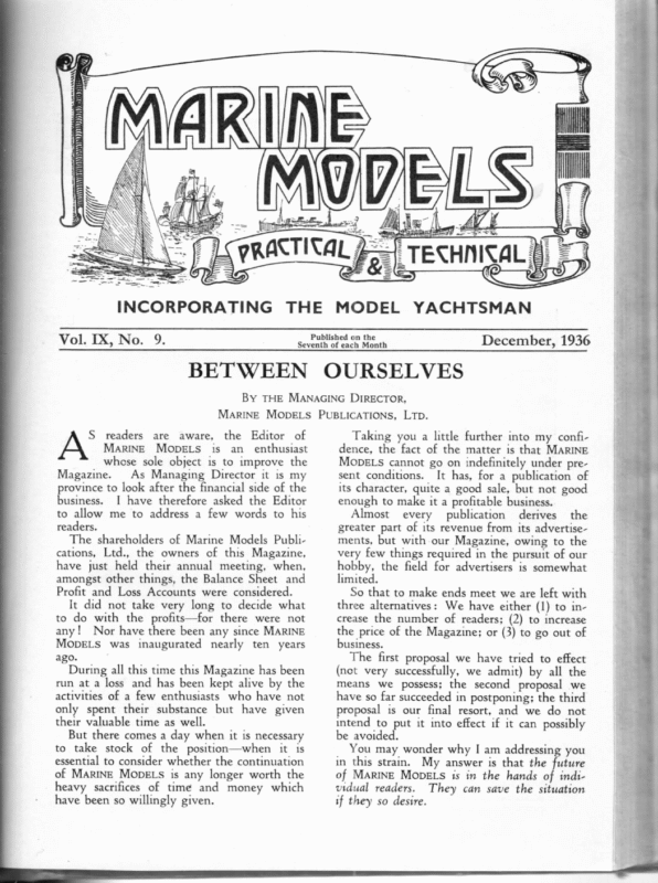
il ZB Vill zp ttle a INCORPORATING Vol. IX, No. 9. THE MODEL YACHTSMAN December, 1936 Published on the Seventh of each Month BETWEEN OURSELVES By THE MANAGING DIRECTOR, MARINE MODELS PUBLICATIONS, LTD. S readers are aware, the Editor of MaRINE MODELS is an_ enthusiast whose sole object is to improve the Magazine. As Managing Director it is my province to look after the financial side of the business. I have therefore asked the Editor to allow me to address a few words to his readers. The shareholders of Marine Models Publications, Ltd., the owners of this Magazine, have just held their annual meeting, when, amongst other things, the Balance Sheet and Profit and Loss Accounts were considered. It did not take very long to decide what to do with the profits—for there were not any! Nor have there been any since MARINE MODELS was inaugurated nearly ten years ago. During all this time this Magazine has been run at a loss and has been kept alive by the activities of a few enthusiasts who have not only spent their substance but have given their valuable time as well. But there comes a day when it is necessary to take stock of the position—when it 1s essential to consider whether the continuation of MARINE MODELS is any longer worth the heavy sacrifices of time and money which have been so willingly given. Taking you a little further into my confidence, the fact of the matter is that MARINE MODELS cannot go on indefinitely under present conditions. It has, for a publication of its character, quite a good sale, but not good enough to make it a profitable business. Almost every publication derives the greater part of its revenue from its advertisements, but with our Magazine, owing to the very few things required in the pursuit of our hobby, the field for advertisers is somewhat limited. So that to make ends meet we are left with three alternatives: We have either (1) to increase the number of readers; (2) to increase the price of the Magazine; or (3) to go out of business. The first proposal we have tried to effect (not very successfully, we admit) by all the means we possess; the second proposal we have so far succeeded in postponing; the third proposal is our final resort, and we do not intend to put it into effect if it can possibly be avoided. You may wonder why I am addressing you in this strain. My answer is that the future of MARINE MOopELs ts in the hands of individual readers. They can save the situation if they so desire.
256 | MARINE How? By recommending the Magazine to their friends; by sending a subscription for a year’s copies instead of purchasing a copy intermittently, or reading the Magazine at the club, or borrowing it from a friend; by inducing their clubs to advertise their regattas, etc., in our columns. We want to double the circulation of MARINE MODELS; we want to increase its advertising revenue; we want to increase its size, its scope and its interest. MODELS Then we shall be able to make ends meet and sail into smooth waters. We honestly believe MARINE MODELS is worth fighting for. It is one of the bestwritten and best-printed magazines you can get. It is a credit to the hobby we all love so much. If you let it die you will probably never be able to replace it. Will you help us? You can if you will. Thank you in advance! ENCOURAGING THE JUNIORS IN GERMANY SCHOOL CONTEST IN HAMBURG On. September 30 the Board of Education in Hamburg had arranged a model yacht competition in the Hamburg Zoo. In 20 public schools, being members of the German Model Sailing Association, nearly 100 models, complying to the Association’s ‘* School Class,’’ were built by schoolboys in the wood-working shops of their schools during the last summer. Most of these models were completed, and had their first contest on the new model sailing pond, which is situated in the Hamburg Zoo. The day after the regatta 115 models were exhibited in a little showroom of the created much interest, and were greatly admired by all visitors. Zoo, The above photograph shows a number of these models. H. F. WarRK, Hamburg.
MODELS 257 Et Sa MARINE years yet. This river tug forms a striking contrast to the ** Ackland Cross ” upon which ‘ Boadicea,” the modern sea-going tug included in “* How to Build a Model Steamer,” is based. But to Londoners, particularly those working on or by the River, the old ‘* Danube Il’ forms an attractive prototype. This second edition of the * Danube II” belongs to Mr. G. H. Adams and his 17-yearold son. In passing I may mention that there is at least one other “* Danube II” model in existence, though I have never seen her. But to return to Mr. Adams’ model, which has rather an interesting history. The hull was built in 1913 by Mr. E. Vanner and is, as one would expect, excellently shaped, but owing to the War the model was never completed. The hull lay about for many years, and eventually passed into the possession of Mr. Adams, Snr. In the winter of 1934-35, the hull was fitted out rather sketchily as a river tug and named the “Britain.” Her owners were by no means satisfied, however, and, during the winter of 1935-36, she was taken home and stripped down. This time it was decided to makea really fine job of her, and, as Mr. Ronald Adams, the junior partner, works at the Docks and knows the “ Danube II” well, this tug was selected as a prototype. The original drawings from which Mr. Pierson’s model was built were then borrowed from Mr. W. L. Blaney. It may be added that these drawings were the work of Mr. Blaney, Mr. Victor Davis and Mr. W. Morss, the latter of whom built the original “ Danube II” model. The hull is 44in. long by 9in. beam, built of tinplate. The plant consists of a singlecylinder, double-acting, slide-valve engine, gin. bore by lin. stroke, and a centre flue marine type boiler. The boiler measures 10in. z oa i ay é HE plans of Mr. H. W. Eastaugh’s motor yacht now being ready, they are included in this issue of MARINE MopELs. Before making a few comments on these, | may mention that I heard (though I cannot vouch for its truth) that Mr. Bomford, the owner of her prototype, found it difficult to see his mooring buoy when coming up to it on account of the high, flaring bow. He accordingly had a sort of periscope made, which overcame this difficulty. The name of Mr. Eastaugh’s model is taken from the prototype, but why did her owner call a graceful yacht by such a name as “Titan,” when just two more letters would have made her into the charming ‘‘Titania ’’? The exact displacement shown in the plans is 22 lb., but it would improve the boat to make her about 24 lb., and put her down a little more, as the owner has apparently done. The twin-screws are not shown in the plans, but anyone using these plans to build to can easily arrange for either twin or single screws, as he wishes. Full description of this interesting little vessel was given in the October issue of MARINE MODELS, so | will commend the plans to readers and pass to another subject. During the past few days I have had the pleasure of inspecting another model of the tub “* Danube II.” A few months ago I described Mr. F. J. Pierson’s model of this little vessel, and here is a rival. The prototype is a well-known Thames tug belonging to, the Tilbury Contracting & Dredging Co. I am not sure when she was built, but it was some time before the War. Since then the old boat has steadily plugged up and down the Thames going about her lawful occasions. The tug has always been well kept up and should be good for many neice (Continued from page 236.)
258 MARINE by 5in., and has an oval flue tube 3in. by 2in. The boiler is all copper, including the ends, and there are 12 crossed tubes of jin. diameter. There is a smoke box at the afterend of the boiler 3in. long. The smoke box is of thin sheet riveted up, and, in order to bring the uptake to the correct position for the funnel, is made with a sort of horizontal extension along the top of the boiler itself. The uptake proper fits into the end of this. The petrol blowlamp has a container 3in. x 4in., the flame tube being 4in. x 1}in., well nipped in at the end. The latter is a pattern The supplied by Messrs. Bassett Lowke. shaft is 7%:in. stainless steel, and the propeller three-bladed, 34in. diameter, the blades being ee tee mappa og (epee – l4in. wide. The deckwork is very attractively finished, and the fittings are much the same as detailed in my account of the original “ Danube II” model. There are one or two little points, however, that are well worth mentioning. The lights in the engineroom skylight and the ports in the superstructure are made from sail eyelets glazed with sheet celluloid. This is an extremely good idea, as these eyelets are light and cheap, and obtainable in many sizes. On the after-deck is a small hatch, which gives access to the after-peak on the prototype. On the model this is lined with cord, and has a line coiled away under it. This forms a salvage buoy in case of accidents. The deck is ;%in. kiln-dried sycamore, well MODELS protected with lead paint on the underside. The deck lining was done as follows: The wood was french polished, after which the lines were first scribed and then inked in with indian ink. After this the deck was lightly rubbed down and finally varnished. The white paint on the top of the deckhouses was put on with white lead flatting undercoats, well rubbed down and finished with white lacquer. To make the lacquer flow easily, it was well warmed by standing the tin in hot water. The ventilators were made from gramophone needle cups, with a brass wire ring soldered round the cowl. Considerable thought has been expended on the parts of the deck which are arranged to lift off, and, though these are very inconspicuous, good access is given to all vital parts of the machinery without trouble. The stanchions round the bridge have their lower ends fixed into a strip of half-round copper. The holes for the stanchions are drilled in the strip and countersunk on the underside. The stanchions are then inserted and soldered into place from the underside. This makes a very strong job, and as the rails on a model are frequently a weak spot, this method is worth noting. I am often asked what clearance should be given between the uptake and the outer funnel. This is rather a difficult question to answer as it all depends on the amount of heat MODEL OF RIVER TUG ‘*‘ DANUBE II ’’ BUILT BY MR. G. H. ADAMS
MARINE MODELS 259 DECK VIEW OF MODEL RIVER TUG ‘** DANUBE II” which is being allowed to go to waste up the funnel. In this model of the ‘“ Danube II” about tin. clearance is given all round, but in this case the smoke box extension undoubtedly helps to keep things cool. The moral is that one should arrange matters so that heat is not wasted. If heat is wasted, obviously a much bigger flame is needed to produce the same amount of steam. Owing to pressure of work I have not been able to make much progress on my destroyer model, but I have been steadily gathering suitable data as to deck lay-out, fittings, etc., and hope to have considerable progress to report by the time we come to the January number of MARINE MODELS. I was interested recently when a model builder showed me a propeller made up simi- larly to the new one ee my destroyer, which I described last month. In this case the three discs for the blades were three halfpennies, so I suppose he has a three halfpenny pro- peller, and I can assure readers it is not a 24d. one either! In a recent number of this Magazine, a tip was given for making boats for a model liner or similar vessel from paper. A letter just received mentions this wrinkle, and states that it has been found most successful. If one does not have one’s back numbers of MARINE Mope-s bound, and has insufficient storage for preserving the whole numbers, it is not a bad idea to cut out wrinkles like the above and stick them into a scrapbook. If one preserves everything of the kind one comes across, one’s scrapbook soon becomes a mine of valuable information. I have been lent a very ingenious little gadget for making rail stanchions, and I hope to describe and illustrate this shortly. The model steamer builder will find it worth his while to read carefully the series of articles on Naval Architecture that is now appearing in this Magazine. Even if one does not actually design one’s own boat, and is a builder rather than a designer, it is highly desirable to master the rudiments of designing since it enables one to build a better model, and avoid many pitfalls. There are far too many boats spoiled for lack of a little knowledge often of quite simple points. (To be continued.)
260 MARINE MODELS PETROL ENGINE and HYDROPLANE TOPICS By J. B. INNOCENT (Continued from page 233.) N designing the mainshaft of an engine oP ers o ~ eranSe dade edeen ee oe ae 0. | the considerations to be borne in mind are that it shall be rigid under load, provide ample bearing areas, enable the balance weights to be as near the out-of-balance centre as possible, the minimisation of oil drag, and the possibilities of accurate production in suitable material. There are two types of crankshaft possible —the overhung type with no main bearing to support one side, and which has the balance weight set to one side of the out-of-balance load line, and the full crank, which is evenly supported and balanced. These two types are further subdivided into solid shafts, i.e., those actually formed from one piece or from a number of pieces permanently fixed together by such means as brazing, and_ usually machined after assembly, and the built-up type, formed of already finished pieces, which are bolted, pressed or riveted together. Varying degrees between the two methods of assembly are possible, so that the number of non-permanent joints may vary from none to four. If the same amount of metal is used in the same position in any type, it will be equally rigid with any other of similar design, provided the joins are correctly made, but it may necessitate variation in the big-end design of the connecting rod. Of course, the overhung crank is not such a sound engineering proposition as the full crank, owing to the one-sided support, but it has its uses. “Little Star” is built in this manner, and it seems eminently suitable, but M. Suzor, who has also made use of this type, has experienced a number of shaft failures since passing the forty mark. I do not think anybody could accuse M. Suzor of indifferent design or workmanship, and I know his choice of material is excellent, thus I conclude that the overhung crank just won’t stick it at his power output and engine speed. A further subdivision of the full crank type of shaft is possible into those with the flywheel at one end of the shaft, and those wherein the flywheel is formed in two halves, integral with the cranks. The latter type, which I favour, is really only possible with a built-up shaft. Its chief advantages are the increases in rigidity, brought about by the inevitable supporting of the cranks by the metal forming the flywheels, and by the further support when working of the rotating mass of the wheels, which naturally tend to check any tendency to whip. Oil drag can be increased by using inside wheels, but by providing sufficient clearance, polishing the surfaces and keeping down the free oil in the crankcase, it is probably kept lower than when bl crank arms and balance weights are used. I do not think there is any doubt that it Is easiest to make a solid shaft of the overhung type, with the difficulty increasing through the solid full crank to fully built-up inside flywheel affairs. For anything but racing I would not consider a fully built-up job, and for racing I would use nothing. else. The problems to be faced in machining a solid shaft are connected with setting it up so that the big-end pin is both parallel to and in line with the mainshaft, and with the difficulty of getting at the pin to turn it, masked as it is by the cranks and balance weights. If an overhung pin is used, the second difficulty is automatically solved, but otherwise three narrow but deep tools will be required, one left hand, one right, and one straight, and the finish will largely depend on skill. To get the big-end pin and shaft true with each other, the rod forming the big-end should, if possible, be extended sufficiently to be mounted between the centres. Now, presuming you are using a brazed-up full crankshaft, formed of one rod for the mainshaft, two cranks, and a rod for the big-end, and that the cranks have been formed together, and the rods accurately centred before brazing, and that the brazing is completed, you should proceed as follows: First cut away the centre section of the mainshaft between the cranks, and heat up the shaft to barely red, leave it to cool slowly, and rest it for a day or so. It should now be free from internal strain, so clean out the centres and try it in the lathe to check the relative position of the two sets of centres. The check should be taken on the mainshaft when the assembly is mounted first in the mainshaft centres and then in the big-end centres. Care must be
MARINE taken to see that you do not distort the shaft, as the centre of the mainshaft is now removed. Check in two planes to verify both throw and alignment. Correct any error by scraping the centres, being particularly careful to get the throw right. Proceed by first machining the big-end, and then carefully pack between the webs so that the shaft is not distorted, and machine the mainshaft, having previously cut away the extensions of the big-end. There is another method of operating on any solid type of shaft wherein the mainshaft is turned first, and a Keats’ angle-plate is then used to hold the assembly by the finished mainshaft for the machining of the big-end pin. For those who do not know the Keats’ plate, I had better explain that it is a V-block with an integral back-plate for bolting to the face-plate, the V-base being at right angles to the face-plate. This system relies on the accuracy of the Keats’ plate, and the stiffness of the face-plate when carrying this weight. The Exe lathe people have now taken over the manufacture of these plates, so they should be beyond suspicion. With this method care is necessary to avoid bruising the shaft by the clamp, and to see that the shaft does not twist in the groove. Should it twist, a nasty dig-in will result; at the same time excessive tightening will increase the tendency to bruise. If possible, a stop should be arranged to take the weight of the cut, which should be kept as light as possible. If your ambitions run to a built-up job, you must decide whether your crank is to be solid or separate from the mainshaft. Should you decide on separate shafts, they should preferably be fitted to the cranks or flywheels by tapers with keys, though a parallel keyed fit will work if the fitting is right. First the shafts should be made between centres and finished completely. Next the wheel blanks are roughly trued-up and reduced to a little over finished size. The centre hole is drilled and bored with great care to see that the tapers fit correctly, and the wheel faced off. Remove the wheel from the chuck, and, using the shaft for an arbor, mount it between centres. It should run true on the face which was last machined when pushed home on the taper; lightly face-off the back of the wheel to take the mainshaft nut, and then, with the nut in place, complete the facing. Treat the second wheel in the same manner and the first stage is complete. Any inaccuracy noted in MODELS 261 the face, which should run true, may be due to the headstock centre, so this should be checked first if trouble is experienced. The next process is to get the wheels precisely the same size. First they should be got as near as possible, and then the same cut of about one thou. should be taken across each with a really nice tool. If you have a mike of sufficient capacity, it should be used to check the sizing, but it is very unlikely that there will be any measurable error provid ed the centres are good, and the tailstock has not been moved. Of course, the slides of the lathe should be in correct adjustment, and the back centre brought up to as near the same pressure as possible. The first wheel should now be marked out for the big-end position, and set-up on the face-plate as near true as possible. If you are not completely confident of your face-pl ate, take a very light cut across at very low speed to true it up, using a flat-topped tool with a round nose. Watch for any tendency the wheel may have to rock when held against the face- plate. It should not rock, and, if it does, the lathe is not facing flat; first look to the thrust adjustment and then all you can do is to undercut the face of the wheel slightly, so that it can only sit down on the rim. Having got the wheel clamped in position, preferably without the mainshaft in place, clamp two stops on the face-plate touching the wheel. The stops should have nice, clean faces to offer to the wheel, and if something with a ground surface can be used so much the better. Slack off the wheel clumps, press the wheel against the stops, and tighten up; this is a precaution and should leave the wheel in the same position. You may now proceed to drill and bore for the big-end pin. Having finished the first hole and cut away as much metal as possible for balance and to accommedate the pin, remove the first wheel and put the second in position against the stops. Treat the second hole in the same way as the first, and you know that your crank throws are correct. You may now finish the other faces around the pin, and cut away as much of the excess metal for balancing as you think advis- able. This cutting out for balance is a fiddling job and leaves a number of intersecting, circular cut-outs, which must be run into one by partially rotating the work by hand— commonly called rotary shaping for want of a better name. When clamping the wheels to (Continued at foot of page 262.)
262 MARINE MODELS SHIPS’ ARMAMENTS By A. P. ISARD, A.M.I.Mech.E. (Continued from page 231.) OUND about the year 1778 the Carron R Company, of Carron, in Scotland, ironfounders and shipbuilders, brought out a remarkable weapon somewhat similar to the cohorn under the name of “ Carronade.” This proved to be very popular and ultimately commanded very large sales. It was short and comparatively light with a relatively large bore, which took the (more or less) standard long-gun ball of the period. This gun, however, was designed for short range, and used a much lighter charge of powder than was commonly employed. These very obvious advantages quickly gained for it considerable acclamation, and it was at first extensively used on merchantmen for protection against privateers, marauders and pirates. Attacks upon merchantmen were common, and it is interesting to note that the Carron Company advertised that its vessels sailed to and from London regularly without waiting for a convoy, and that-its vessels were fitted out in a most complete manner for defence. As a condition of their being given passage, all steerage passengers had to undertake to assist in the defence of the ship if called upon by the captain. The appeal to merchantmen, run as strictly business propositions, was very great, as, owing to the saving in powder by reason of the smaller charges used in this new weapon, less powder had to be provided in the ships’ magazines. At the same time it was strongly contended that the big heavy ball, discharged PETROL ENGINE & HYDROPLANE TOPICS (Continued from page 261.) the face-plate be certain it does not spring. The type of fit between the big-end and wheel is a matter of personal preference; I do not think there is much to choose between a parallel or taper. Probably the stiffest is the parallel used in conjunction with a wide bolting face on the pin. You have still to file the key slots in the flywheels; these should be on the balance weight side. Whether you use an end-milled slot or a Woodruff in the shaft is immaterial, at close range, was more effective than a smaller shot fired at a longer range from the heavy long-gun, especially as most engagements were fought at short range. All these advantages, together with their lighter weight and smaller gun-crews, made for vastly increased efficiency, and gave greater speed to the ship herself, owing to less deadweight. Nevertheless, this gun was not taken up by the Navy Department for some little time. Carronades were made in several sizes, the largest being called the “ Smasher.” This was an 8-in. weapon weighing about 130 cwt., and discharging a fairly well-fitting ball of some 68 lb., using a sinall powder charge of about 54 lb. This gun was never taken up by the Navy Department, but to Lt.-General Melville the invention of the “ Smasher” and subsequent carronades must be accorded. The arguments between the two schools of thought (viz., the big bore, large shot, closerange, devastating, smashing and_timbersplitting carronades, against the long-gun with its superior range but extravagant powder charge and small ball, making a small clean hole in the enemy ships) waxed hot and strong. The big bore won the day, only to be ousted later on, when, with the invention of shell projectiles and rifling, the long-range, high-velocity gun became finally and definitely master of the situation. provided the key fits. In the wheel the key should not touch the bottom of the slots but only the sides, and these it should fit. When the keys are fitted, assemble the wheels and try them in the lathe to make sure the key is not holding them up so that they are out of truth. Oil-ways may now be drilled, any burrs being removed with a scraper, and the wheels are complete except for the nut-locking device. For this I use a thin tin washer, being removed with a scraper, and the wheels punched down into a hole in the wheel and bent up round the nut. (To be continued.)
MARINE MODELS 263 18-POUNDER CARRONADE Scale: tin. = Ift. Reproduced by kind permission of H.M. Admiralty and the Stationery Office. The original drawing has the following notes on it:— NAVY OFFICE, 30th July, 1808. Profile and plan nade conformable of an to 18-pounder Carro- an Admiralty dated 30th July, 1808. after Carronades on the poop with trucks for the order Directing the two more to be fitted easy removeing them to the nght Aft porte on the poop— N.B.—When useing them right aft the Large trucks are to be put on the hind axle for the purpose of raiseing the inner end of the Carriage to ease the recoil of the Carronade, Like most innovations, the carronade met with some opposition and criticism, the chief of these objections being the difficulty of producing nicely fitting balls upon which so much of the gun’s efficiency depended. This was overcome by making the bores to suit the diameters of the balls—a reversal of ordinary engineering practice, as it is to-day, so when the diameter of the ball was agreed upon, the weapons were made accordingly. In small arms this curious custom is responsible for our present-day nomenclature of shot-gun sizes. For instance, No. 12 bore means that the diameter of the bore of the gun is equal to the diameter of a spherical lead ball when twelve balls go to the pound, and so on for other different bores. It was the habit to scoff at new inventions in past times as it is to-day, and we read with amusement when Mr. Pepys says in his diary, “ The visit to the Old Artillery Ground near Spitalfields to see a new gun which, from the shortness and bigness, they do call Punchinelle, shot truer to a mark and was easier to manage and had no greater recoil to the great regret of the old gunners… . ” The drawing herewith produced is of an 18-pounder carronade ordered by the Admi- ralty about the middle of the year 1808, and is published by special permission; the drawing is half-inch scale. We will study this delightfully interesting drawing in the next issue. (To be continued.)
264 MARINE MODELS SIMPLE NAVAL ARCHITECTURE FOR MODEL YACHTSMEN & MARINE MODELLERS By YARDSTICK (Continued from page 227.) culate the volume of water she displaces and ascertain the fore-and-aft position of the Centre of Gravity (C.G.). As these are usually calculated simultaneously, some explanation is desirable before coming to the actual methods employed. If a weight is suspended from a nail by a string, it automatically places itself vertically Buoyancy is a supporting below the nail. force and can be considered as an up-thrust with its power concentrated at the Centre of Buoyancy (C.B.). On the other hand, gravity is a depressing force and can be considered as a downpull on the vessel with its force concentrated at the C.G. Pie. =o J eae eg eer ne eee 2 N order to ensure a vessel floating on her designed L.W.L. and in the correct foreand-aft trim, we have to be able to cal- Fig. 3. Za _) Ship in correct trim. So long as the C.G. is lower than the C.B., the position is analogous to the weight suspended from the nail, and the C.G. will automatically range itself vertically below the C.B. This is shown in Fig. 3, where a vessel has her C.G. forward of the C.B. In consequence the C.G. has ranged itself beneath the C.B., putting the ship by the head. In Fig. 4 the ship has been trimmed by moving ballast aft until the C.G. has moved aft to its correct position in the same fore-and-aft station as the C.B. and the vessel is now in her proper fore-and-aft trim. If the C.G. is above the C.B. the position is somewhat different, but as will be seen later, a vessel can be perfectly safe under these conditions, being stable and able to right herself at all ordinary angles of heel. Nevertheless, the lower the C.G. the stiffer will the vessel be, and as a reserve margin of stability is advantageous to model steamers as well as model yachts, it is necessary to cut top- hamper down and keep all weights as low as possible in any sort of model. As the C.B. of the vessel is the C.G. of the volume of water displaced, we must be able to calculate this accurately. This brings us to the mathematics, and for the benefit of those to whom calculations are anathema, may | add that the mathematics involved are within the powers of an ordinarily intelligent boy of 12 or 14! The first thing is to ascertain the section areas. A half-section is shown in Fig. 5, but all that concerns us is the underwater portion ABC, and on this AB represents the L.W.L., and BC the Centreline. As was mentioned in my first article, we work on a half-model, and to find the full area of a section, it is obviously only necessary to multiply the halfsection area by 2, or we can calculate out the whole half-model and simply multiply the L *S1 eG. Fig. 4. _J Ship trimmed by the head. displacement ascertained by 2. Some of the knowing ones possibly say to themselves “ Simpson’s Rule,” but this rule is awkward, as the base has to be divided into an even number of parts, and there are better methods of making this calculation. Divide either AB or BC into any convenient number of equal parts. As AB is 5.44in. and BC Qin., it is obvious that the latter-is more convenient to work on. In addition, it is much the longer and therefore more suitable to use as a base. For example, let us divide BC into nine equal parts. At these points erect the perpendiculars P*, P*, P*, P°, etc. AB becomes P’, and the point C becomes P’’. These perpendiculars are known as the Ordinates of the figure ABC, and it will be seen that the ordinates have divided the whole figure into nine smaller figures. The line BC which is the base of the whole figure is Qin. long and divided into nine parts, so the Distance between the ordinates is lin. Now the smaller figures into which ABC is divided are trapezoids (figures having two
MARINE MODELS 265 Ordinates can be used and that considerably less figures are used. Simpson’s Rule is very slightly more accurate, but with either rule the degree of accuracy is increased by using more Ordinates. A x B P! pz yi Ordinate Length — Product Half-Section Pt 5.44+2=2.72 with Ordinates p23 F Now to work out our half-section : — Fig. 5. P? drawn ready 4 ‘ peers ep. p* 30 x P* 0.68 x 1=0.68 ee mg Teepe pe 4.48x 1=4.48 P* . 328 «x 1=3.28 P* P® zoidal Rule. p? 0.78 x 1=0.78 0.87 x 1 =0.87 P® 0.86 x 1=0.86 P** 0.00 +2=0.00 ps 16.28 x 1 = 16.28 Pp? Cc r 1=0. It should be added that all of these methods io assume that the small figures have side curved, so that the calculated area is slightly under the exact area. Obviously the closer the ordinates are placed, the less will be the proportionate error. It will also be found that the results obtained by various methods of calculation will vary slightly. A method of finding the area without calculation is to plot the section on paper squared in inches and tenths of an inch. Each big square then tepresents one sq. in., and each small one .01 sq. in. Parts of the hundredth squares can easily be averaged out by eye and allowed for. parallel sides), and their areas can be found by averaging the two parallel sides and multiplying by the Distance. . An alternative to working the small figures out separately and totalling them, is to average the ordinates and multiply by the length of the base for the whole figure. The best way, however, is to use the Trapezoidal Rule. Halve the first and last ordinates but take the whole of the intermediate ones, and total. This gives the sum of the Products of the ordinates. Multiply the sum of the Products by the Distance, and the result is Professional naval architects use an ingenious little instrument, called a Planimeter, for measuring section areas. This saves a lot of time, but as the instrument costs several the area of. the whole figure. The advantages of the Trapezoidal Rule over Simpson’s Rule are that any number of aoe 0 | 2 four straight sides, whereas, in fact, these have one 3 4 Fig. 6. 5 6 Curve of Areas 7 8 3 10
266 MARINE pounds, most amateurs will not go to the expense. Having measured all the half-section areas, these are again listed, and to work out the displacement of the vessel the Trapezoidal Rule is again brought into operation. In this case the half-section areas form the ordinates and the Centreline is the base, the spacing of the sections being the Distance. This can be graphically plotted as in Fig. 6, the resulting figure being known as the “Curve of Areas.” To obtain the displacement, the sum of the Products of the half-section areas is multiplied by the Distance. This gives the volume (or displacement) of the half-model in cubic inches. To get the displacement of the whole MODELS Z2 3vs3 a HB 0 | 2 3 4 5 6 0.00 1.69 4.40 6.96 9.13 9.89 9.50 7 8 9 10 ever, is to divide the displacement by 27 for salt water, and by 27.65 for fresh water, which gives the weight in pounds and decimals of a pound avoirdupois. The next step is to ascertain the fore-andaft position of the C.B. This is done by taking moments-—another very simple operation. The moment of any section is found by multiplying the Product of the half-section area by its distance abaft the forward one. For instance, in our worked example, Section 0 is 0 sections abaft itself, Section | is 1 section (=Distance x 1) abaft Section 0, Section 2 is 2 sections (=Distance x 2) abaft Section 0, etc. It simplifies the calculation to multiply the individual Products by the number of sections and multiply the result by the Distance. Having ascertained the sum of the Moments, this is divided by the sum of the Products, which gives the number of sections the C.B. is abaft the forward one. In the worked example this is 5.13, which, in turn, is multiplied by the Distance 4, and gives the final position 20.52in. abaft Section 0. A worked example showing how displacement, weight and C.B. are found is given at the top of the next column. For those who dislike figures so much that they will go to any trouble to avoid them, it may be mentioned that the position of the C.B. can be ascertained equally well by cutting the Curve of Areas out of stiff paper and balancing it on a pin. a = 1=792 x 1 = 5.66 x l=205 «x 0.00 x 5 = 0.00 x vessel multiply by 2. From the displacement the weight can be ascertained quite easily. A cubic inch of salt water weighs .592 0z., and a cubic inch of fresh .577 0z., so a little multiplication will soon give the weight. The easiest way, how- = x .5 = 0.00 x x 1=169 x x 1= 4.40 x x 1 = 6.96 x x 1=913 x x 1= 989 x x 1 = 9.50 x 792% 5.66 x 205 « 3 8 57.20 a= = O0= 1= 2= 3 = 4 = 5 = 6 = 0.00 1.69 8.80 20.88 3652 49.45 57.00 = 0.00 7 8 9 10 = 55.44 = 45.28 = 18.45 293.51 For Displacement—57.20 x 4 (D)=228.80 cu. in. For Whole Model—228.80 x 2= 457.60 cu. in. For Weight (Fresh Water)—457.60 ~ 27.65 = 16.54 lb. To find C.B.—293.51 + 57.20 x 4 =5.13 x 4=20.52 in. abaft Sec. No. 0. In calculating the displacement it was assumed that the plans being used were fullsize, but if these are on a smaller scale, this must, of course, be taken into account. In using scale plans, plain linear measurements (such as length, breadth, etc.) are simply multiplied by the scale. Superficial measurements (such as section areas, sail areas, etc.), being square measures, are multiplied by the square of the scale. Volumetric measurements (such as displacement), being cubic measures, are multiplied by the cube of the scale. Thus, if the model is to be three times the size of the drawing, measurements of length, breadth, etc., are multiplied by 3; section areas, sail area, etc., are multiplied by 9 (37); displacement is multiplied by 27 (3°). This works the reverse way in making a model of a full-scale vessel, and, if making a 3ft. model of a 120ft. vessel (i.e., on a scale of 1/40th of full-size), length, breadth, etc., are divided by 40, section areas by 1,600 (407), and displacement by 64,000 (40%). This explains why a boat should always be built to the size for which it is designed, and why adaptations must be done with skill and common sense. It also accounts for the fact
MARINE that smaller boats require more proportionate breadth and depth. One point to remember in this connection is that length is the only dimension which can be altered in_ its proportion to the others, without en- tirely changing the characteristics of the vessel. So long as the sections remain the same they can be spaced closer together or spaced out without altering the balance of the vessel. On the other hand, if the waterlines are spaced out in order to get greater displacement, the design of the model is entirely altered. The less advanced reader must take this on trust for the moment, but those who understand the Metacentre will understand the exact reason this is so. It will be seen that the mathematics involved:so far are very elementary, and the reader can rest assured that the worst is over when he has got so far! The fin (or keel) should be included in the Curve of Areas, but should be omitted in calculating the Coefficients of Fineness, which we are about to study. If desired, however, a special Curve of Areas of the body only can be taken out as it shows the form of the hull itself. Taking as an in- stance the section shown in Fig. 5, the body down to the ordinate P® would be used in calculating the coefficient of fineness of this model. The Coefficients of Fineness give a comparison of the actual shape of a vessel with a rectangular block of the same dimensions, and provide some of the most reliable data the designer has. In Fig. 7 the midship section of a modern cargo boat model is shown. She has a body depth of 3in., and an extreme beam of 8in. A rectangle has been described round the underwater portion, and will have an area of 8in. x 3in.=24 sq.in. The area of the rectangle exceeds that of the actual section by the shaded portion. The mid-section area is 23.32 sq. in., and is, therefore, 97.16 per cent. MODELS 267 of the rectangle. This proportion is known as the ‘‘ Mid-section Coefficient,” and the coefficient is stated as .9716, It would, however, be impossible to calculate the displacement of a vessel from her length, breadth, draught and Mid-section Coefficient. Given the breadth, body depth and mid-section coefficient, we can calculate the area of the mid-section. Further, the Mid-section Coefficient gives one a very useful means of comparison between various vessels as it is a direct: measure of their form. The next step is to consider the “ Prismatic Coefficient.” Consider a solid block shaped like the mid-section for its full length, as in Fig. 8. As the ends of the vessel are shaped, the volume of the vessel is less than that of the prism. The ratio of the vessel to the prism is its Prismatic Coefficient. In the example shown the mid-section measures 23.32 sq. in., and the model is 40in. long, so the volume of the prism is 23.32 x 40 = 932.8 cu. in. The volume of the actual boat is 569 cu. in., which is 61 per cent. of the prism, so the Prismatic Coefficient is .61. Finally, we come to the “Block Coefficient,” which is the relation the displacement of a vessel bears to that of a solid block having the same length, breadth and depth. A block the size of our present model would measure 40 x 8x 3=960 cu. in. cent. (To be continued.) 7 = Fig. 7. [7] Mid-Section Coefficient The actual model is 569 cu. in., which is 59.27 per cent. of this, so the Block Coefficient is .5927 per Fig. 8. Prismatic Coefficient (see text)
268 MARINE MODELS MODEL MOTOR YACHT “TITAN” DESIGNED BY H.W.EASTAUGH ame Y DISPLACEMENT. 22 Ibs. Scale: One-fifth of full size. . Note: The Model
MARINE MODELS eased in weight to 24 lb., putting her just below the L.W.L. shown on plans 269
270 MARINE SAIL MODELS TYPES By G. W. Munro another. By this I do not mean that | shall attempt to give any of the local types, such as Scottish Zulus or Thames Bawleys. | am dealing purely with the general rigs which are more or less common to all European countries. In this I mean Cutters, Sloops, Ships, Barques, and so on. I shall, in dealing with each type of vessel, give the usual position and proportion for the masts. An attempt will also be made to cover the development of each type over the past 150 years. To start with the smaller classes, we have the Sloops and Cutters. These are one-masted vessels, generally rigged fore and aft, but originally they had square sails as well as the normal fore-and-aft ones. Falconer gives the Cutter as a small vessel commonly navigated in the English Channel, furnished with one mast and a straight running bowsprit that could be run in on the deck occasionally; except for which, and the largeness of their sails, they were rigged much like Sloops. Regarding Sloops, he says a small vessel furnished with one mast, the mainsail of which was attached to a gaff above, to the mast on its foremost edge, and to a boom below, by which it was occasionally shifted to either quarter. It differed from a Cutter by having a fixed standing bowsprit and a jib-stay; nor were the sails generally so large in proportion to the size of the vessel. It must be remembered that there was another vessel known as a Sloop; this was a much larger vessel and very similar to a Corvette. These will take their place in a later article as we progress. Very similar to a Cutter or a Sloop is the Smack. This little vessel was intended for fishing, whereas Cutters and Sloops were as ey Sided yn eo etter eee | N the present short series of articles | hope to show a few of the characteristics which go to distinguish one sailing ship from Royal Navy carriers. craft as well as small cargo The position of the mast must vary with any slight variation in rig, but a very successful position will be found to be .112 of the L.W.L. forward of the middle of the L.W.L. The mast should rake about | in 12. The length of the mast for a Cutter in the Navy is as follows: Add together the length of the deck, the extreme breadth and the depth of the hold; and three-quarters of the sum is the length of the mainmast. The diameter of the mast should be 3in. for every yard in length. The above is the old Royal Navy rule. Hedderwick, in 1830, says a Smack or Sloop should have its mast 1/7th of the L.W.L. forward of the middle of the L.W.L., and that it should rake 4in. to the foot. John Edye, in 1832, says that Royal Navy Cutters have their mast placed 10/25ths of the length of the vessel on the L.W.L. The length of the vessel he mentions is 67ft. 3in. on deck. The extreme breadth is 24ft. Sin. and the depth of hold is 10ft. 7in. On these figures he gets a mast 76ft. 8in. long with a given diameter of 20in. This Cutter is given as of 161 tons, and it is interesting to compare it with Hedderwick’s Smack of 173 tons, and which has a length on deck of 77ft. 5in., breadth of 23ft., and depth of hold, 12ft. 6in. Hedderwick’s mast is found in the following manner: To half the length of the L.W.L. add three times the breadth and the depth of hold, and gths this amount is the length of the mast. On the above vessel with a L.W.L. of 74ft. it works out at 76ft. The diameter of the mast is given as lin. for every 34ft. in length. The mast-head should be ith the given length of the mast. I do not know the exact length of Edye’s mast-head, but it appears to be 13ft. from the scale drawing, and this is very near the 4th given above. Coming on to the middle of the century | find there was a Sloop yacht of 125 tons. She was a vessel of 63ft. 9in. length, and 22ft. 6in. breadth. She had a mast 74ft. 2in. long, diameter 20in., and headed length 13ft. Reverting to the 1815 rule of the Royal Navy, we have Cutters of 200 tons with masts 88ft. long and 22in. diameter. It will be seen from this that there was not much difference in the proportions of these gaff-rigged one-masted vessels of the last century. With the position, size and rake of the main or lower mast, we can go ahead and proportion the rest of the spars and rigging.
MARINE MODELS 271 It is usual to consider the bowsprit as a mast, and, as it is rather an important fixture, we may as well deal with it before going on to the top-masts and spars. The Royal Navy rule of 1815 says bowsprits should be 3/5ths the length of the mainmast for ships of 74. guns and under, but this would hardly work on a one-masted vessel, and we find that the 200-ton Cutter had a bowsprit of 64ft. The diameter should be 2in. less than the mainmast. The figure given also conforms to this rule, and is 20in. John Edye’s Royal Navy 161-tonner has a bowsprit 57ft. 3in. long with a diameter of 16in. Hedderwick’s Smack had a bowsprit $rds of the vessel’s length per register, or 3rds of the length of L.W.L.; or, as allowed by Act of Parliament, rds of the length on deck. Lastly, we have the Sloop Yacht of the middle of the century with a bowsprit 38ft. 8in. long with a diameter of 144in. The amount of stive seems to vary quite a lot with each class rather than change with the years. We are accustomed to seeing Cutter with horizontal, or slightly bent, bowsprits. Others, again, follow the rise of sheer, but perhaps the sheer has been put in to agree with the already arranged stive of bowsprit. This should vary between 73in. to 104in. in every 12ft. of length. The length of the main-boom is commonly given as equal to the length of the keel, but Hedderwick says that it is more correct to find it by multiplying the L.W.L. by .92. The diameter should be lin. for every 44ft. in length at the sheet, and 3rds this amount at the mast. These proportions look wellbalanced and seem to have been accepted for a long period, or until the racing yachts started to vie with each other for excessive sail spread. A very common length for the gaff is 3rds the boom. The greatest diameter of the gaff is at the mast, and this should be lin. for every 34ft. in length. The outer end should be 6/10ths the diameter of the inner end. The cross-jack yard is generally about 9/12ths of the length of L.W.L.; or if this looks rather long, .72 of the L.W.L. The request for this series of articles came in rather late, and as the writer has been kept very busy in the shipyards lately it has been impossible to include any diagrams, but these will be included next time. (To be continued.) A FINE MODEL SHIP There are nowadays quite a number of men interested in riggers. The above charming picture is of ‘* Minne- building and sailing models of square ha-ha ”’ of the Ryde M.Y.C. (Isle of Wight). picturesque model is well known to This habitués and visitors to the Ryde sailing water where she is in- variably the centre of attraction. Photograph of a model brigantine will be found on page 279, and we hope to publish a picture of a model topsail schooner in our January issue. FOR SALE 10-RATER. ‘‘ DIVINE LADY.”’ Winner Eastbourne Silver Ship, Baroness Chessbron’s Trophy, Hove Corporation Bowl, 1934-35-36, and many other prizes. Perfect condition, 15 gns. Keyworth, 29, Norton Road, Hove.
272 MARINE PR F- an, OL — 7 aK + MODELS TH ae [In order to enable us to make the best use of the space at our disposal, Club Secretaries are requested to make their reports brief and to the point.—Epiror, MARINE MODELS.| BRADFORD M.Y.C. The race for the ‘* Temple ’’ Cup, on November 8, was sailed in a second-suit wind. This Cup, donated by Mr. G. Kitchen, is competed for annually in turn by each of the club’s four classes, and this year it was the turn of the 10-raters. The yachts are run in pairs on the tournament system, but sail out-and-home, one point being scored for the complete round. The result was: Ist, ‘‘Bonito”’ (H. S. Haigh); 2nd, ‘* X ”’ (F. C. Hirst). Also competed: ‘‘Albatross’’ (G. Whittaker), ‘‘Cintra Duinn”’ (H. Atkinson), ‘‘ Freda’’ (W. B. Waddington), ** Waveney ”’ (J. P. Clapham), and ‘* Whimbrel II ”’ (H. Short). The 0.0.D. was A. Arnold, assisted by Eric Roberts and A. L. Porter. The ** Mirfield ’’ Cup (10-raters), presented by the late Mr. E. Gill, was raced for on November 14. The wind was light and fluky. Result: Ist, s—= “* Freda ’’ (W. B. Waddington) with 14 points out of a possible 20; 2nd, ‘‘ Waveney ”’ (J. P. Clapham), 12. Also sailed: ‘* Albatross ’’ (G. W. Whittaker); ‘“* Bonito ’’ (H. S. Haigh), and ‘* Raven’ (G. Kitchen). The O.0.D. was E. Marx, assisted by Eric Roberts, H. Atkinson, and A. Arnold. The Annual General Meeting is at the Stone Trough Inn, Rawdon, on December 9. Je Pc. FLEETWOOD M.Y. & P.B.C. A 10-rater Spoon race, on October 10, was sailed in a light, variable wind. Result: ‘‘ Venture ”’ (E. G. Wade), 27; ‘* Bett Spriggs ’’ (J. Rigby), 23; ** Velindre ’’ (J. Thomasson), 22; ‘* Lettie ’’ (A. Foster), 214; ‘* Devonia’’ (J. T. Anyon), 17; ‘* Eleanor ‘’ (J. Roberts), 16; ‘‘ Mary’? (T. Raw- linson), 134; ** Lawmarion ”’ (J. Livesey), 0. A 36in. Spoon race was sailed in a nice, steady breeze on October 17. Result: ** Betty ’’ (H. Leadbetter), 18; ‘‘ Lady Anne’’ (T. Tipping), 16; ** Flash ’’ (J. Coulbarn), 13; ‘*‘ Mary ’’ (P. Corlett), 9; ** Fracas ’’ (J. W. Roberts), 7. An A-class Spoon race, on October 24, marked the end of the club’s season. A strong Westerly gale (39 m.p.h.) blew, accompanied by heavy rain, throughout the race. Result: ‘* Valiant ’’ (J. Darbell), 25; ‘* Vanity ’’ (E. G. Wade), 234; ‘* Capri ”’ (R. G. Pearson), 18; ** Nell’? (W. Hornby), 17; ““ Anne Maree’’ (R. G. Bailey), 15; ‘* Beatrice ’’ (G. E. Heyes), 135; ‘* White Heather II’’ (P. C. Corlett), 9; ‘‘ Marion ’’ (J. Y. Anyon), 4; ‘* Lucia ”’ (A. J. Stewart) withdrawn, damaged. The model yacht lake has now been separated from the Marine Lake, and a powerful pump installed, which can be used at all states of the tide, so that the difficulty of occasional shortage of water has been completely overcome. Plans have been passed for the erection of a more commodious boathouse, which will contain a Club Room, Secretary’s Office, Measuring Room and Store. It will have electric lighting and heating. The proceeds of a Carnival, held during the summer, were handed over to local charities. The sum of £105 was given to Fleetwood Hospital, £10 10s. to the St. John Ambulance Brigade, and £5 5s. to the Women’s Auxiliary Nursing Associa- tion. To date, the club has handed over upwards of £300 to various charities. J. M. SALFORD PARK (BIRMINGHAM) MODEL YACHT CLUB The third annual meeting was held in the large boathouse at Salford Park, on October 17. In the absence of the President, Dr. P. Thornton, M.C., the chair was taken by W. H. Davey, Esq., Viceoe and pioneer of model yachting in the ity. In his opening speech he congratulated the club upon its activities of the season, and especially the Cup winners in the four principal Cup events of the year. Mr. F. A. Blair, winner of the ‘* Thornton’ Trophy for 10-raters, with ‘‘ Onward,” designed by Daniels. Mr. J. Brinkworth, the ‘‘Easton’’ Trophy, for 6-m., with ‘* Noreena,’’ designed by Le Fluffy. Mr. K. W. Kendall, the ‘‘ Evans ’’ Trophy, for 36in. Restricted, for the third year in succession, with ‘‘ Imp,’’ a full-keel model by Daniels. Mr. W. E. Edwards, the Championship Cup, with ** Cub,’” by Alexander. He attributed the increase in membership to the close proximity of the lake to the centre of the City, the splendid stretch of water with its constant water level, the good paths, which are at all times of the year dry and hard, and last but not least, its great attraction for inter-club matches. Mr. Davey thanked the members for their splendid support of the Bournville Club’s open events of the season, and conveyed a friendly message from its members to the members of Salford. The Treasurer’s report showed a considerable balance in hand, which is gratifying to members. The Secretary’s report was short, but did ample justice to progress made during the year, and heartily welcomed the many new members to. the 6-m. ranks. Instead of one Championship Cup for the best average of any class, it was decided to have one Cup for each of the three main classes, namely, 6-m., 10-raters, and 36in. Restricted, and three donors stepped into the breach and the Cups materialised.
: : SLIPPING MAST FITTINGS AST fittings are M shade too big for the spars. To cure this on prone to slip if they are a a wooden mast, put two or three turns of adhesive surgical strapping round the spar under the fitting. On a metal mast use ordinary insulating i tape. Either of these materials can often be successfully employed to fish a broken spar for a temporary repair, and an ordinary lead pencil has been used as a temporary liner for a broken , wooden hollow mast. PILE Members DRIVING of ford M.Y.C. the board their new ee ees « Erdington, Birmingham. i 273 the Brad- constructed walk round sailing water, Larkfield Dam. Member to the ‘Just my you new Leica ssteadying Hammer be cap! pile Man: careful BP aR The proposed amalgamation with the City of Birmingham M.Y.C. was discussed at length, but members unanimously agreed that no useful purpose could be served by it, as it would lessen the possibilities of inter-club matches in the City to the detriment of model yachting. We at Salford Park feel that there is no greater impetus to any outdoor sport than inter-club matches. W. D. CREESE, Hon. Secretary. 2, Leamington Road, Gravelly Hill, MODELS ies MARINE of °? Photograph by aaoent . « “toe Leonard Taylor, Leeds. THE SUCCESSFUL SHARPIE 10- RATER ** WAVENEY,” from the MARINE MODELS design ** STELLA ”’ Built by her owner, J. P. Clapham, Bradford M.Y.C. Leica by Photograph Leonard Leeds Taylor,
er eet MARINE ee Out Scottish Page te AE po SR re. “es ro es wea MODELS “A Star fell out of Heaven.’’ Oh! drat this Stars out of wireless, we must switch it off! Heaven, forsooth. Seems more akin to a shower of meteorites falling upon our unprotected head. Merci, Messieurs. Yes, it is ** STULTOS,’’ and, while thanking our innumerable friends for their correction, we have severely admonished our machine. We will require to get another one—when we can afford the instalments. We appreciate the letter of our friend Mr. Jas. Edwards in our last issue. It is the sort of criticism which is legitimate and designed to be constructive. At the same time we draw issue regarding the remarks about the score cards. These were called for, but one had been blown out of the skipper’s hands and lost in the lake, and others were in a sodden and indecipherable condition. Under these No question circumstances scrutiny was waived. arose, or arises, regarding the correctness of the Official scores. Owing to the unfinished position in which the race had to be left, however, certain competitors had sailed a heat more than others. The advisability of sailing any event sectionally, or in just a single round, is a matter of opinion. In our view the only satisfactory system for a Championship, or any event of equal importance, is the straight-through tournament. No sectional system can approach it, and in the instance under review sectional sailing would not have affected the position in the slightest degree. What beat us was the weather. Far from agreeing that it is impossible to complete a tournament comprising 16 entries at Fleetwood in one day, we would not hesitate to undertake to deal with even more under reasonable conditions, presupposing a prompt start at 9 a.m. The 6-m. National Championship race started at about 10.30 a.m., and at 1 p.m., when the lunch interval was taken, 24 hours’ sailing, 54 heats had been completed, notwithstanding that the wind force had increased to over 35 miles per hour. Assuming that the wind had remained constant even at that, from 2 p.m. until 7 p.m. might quite justifiably be regarded as sufficient for the remaining nominal 93 heats. With a steady breeze of anything from 15 to 25 m.p.h. our experience suggests that 20 entries could be comfortably dealt with under normal circumstances. At the same time we agree that it is safer to allot two days for a race likely to attract an entry of, say, over 15, as an insurance against possible contingencies. For this reason we have already advocated two days for the 6-m. National event in future, and should not be surprised to see the fixture eventually require an even And so, in chastened mood, we longer period. leave the subject. ; The past month has not brought us any serious racing, and a merciful dispensition of providence has decreed that the week-ends should be unsuitable for gardening. On the other hand we have eer concerned with A.G.M.s. been The Scottish Association meeting on October 30 was attended by delegates representing 21 clubs, a most gratifying turnout expressive of active interest in the affairs of the organisation. About three hours were occupied in varied discussion, lively at times, but without discord. The Scottish Registrar reported that the number of craft of the three principal classes on the Scottish Register were: 172 12-m., 178 6-m., and 29 A-class. New registrations during last season were 13, 32 and 5, respectively. Of the 12-m., no less than 11 came from one club, and it is evident this class has outlived its day, although the number still active is, of course, considerable, and likely to persist for some years. Apropos of the Registrar’s report, the Secretary pointed out that, allowing 20 minutes for checking, etc., each certificate, registrations and re-registrations had occupied the Registrar the equivalent of fully 10 days’ continuous working, day and night, without a break! Rather strenuous for a newly-married man, and Mr. Hutton thoroughly deserves the vote of thanks accorded by the meeting. For our part, we think to Mrs. Hutton is due some recognition also. A large number of boats will require re-registration for 1937 (expiration of 1935 certificates), and the Scottish Registrar appeals for early submission of these to avoid possible congestion and consequent delay. The ballot for 1937 Championship races for 12-m. and 6-m. classes went in favour of Kirkwall (Orkney). What price summer holidays? Some considerable discussion arose regarding the venue for the A-class Championship, and eventually it was decided to confine this race to a choice between Saltcoats, Lochend (Coatbridge), Paisley and Greenock, for the next five years, and for the forthcoming season Saltcoats was selected. Personally, we consider this arrangement unfortunate, and, in fact, unfair to our Northern compatriots, among whom, we understand, the A-class is developing in greater proportion than in the other districts. Furthermore, Paisley is, in our opinion, not suitable for this race; there are also certain disabilities in the Greenock waters, and we have serious doubts as to the suitability of Lochend. On the whole, we are very much afraid the restriction imposed will react to the disadvantage of the class, and to our mind it is somewhat selfish. A Committee was appointed to examine the question of the provision of an ade- quate model yacht lake in connection with the projected 1938 Empire Exhibition at Glasgow, and to take steps to advance the matter by all available means. Kilmarnock reported that their boathouse had been blown to pieces and practically all their fleet ruined during the recent storm. Sympathy was expressed by the delegates, and consideration is to be given.as to what means can be adopted to aid the Kilmarnock club to recover from the misfortune. Various other matters had full discussion.
Champion, and is, apparently, an enthusiast. Some interest is being taken in the enterprise by the local Council, and the Convenor of the Recreation Committee, R. Inglis, Esq., took charge of a race on October 10, when 10 competitors, representing Perth, Dundee, and Tayport, were in action. The result went in favour of Perth, with Tayport second, and Dundee in the wake. A considerable amount of interest was evinced by a large number of spectators. Subsequently, the company were entertained to tea, and the inauguration of the Tayport M.Y.C. over the representative model yachts sent with them, permanent asset ade ——— to the City, practically at no cost eee to the citizens at all. We hope there will be influential assistance in the effort to bring it about, and trust it will not be in vain. At the moment of writing the guarantee fund is well on the road to the three-quarter million mark, and there is no doubt the Exhibition itself will be a huge attraction. Quickly speeds the time away, and before our next issue the year will have passed, and again be reborn. We extend to all model yachtsmen, near and far, the old Wish that is still ever new, A Merry Christmas and a Happy New Year. ‘‘ May ye never die till a dead Coo kicks ye.’’ THE SCOTTISH COMMODORE. CHECKING UP ON THE Place the craft deck down on a BACKBONE level surface and erect a line fore and aft about 3ft. above the keel. Half a dozen sailmaker’s needles and string are required for the job. These will make six plummets, which will be ample for checking up. Start by attaching two plummets on the line about the same distance apart, as the overall length of the model. See that the bow and stern of the model are placed exactly opposite these plummets and use the other four on the line for checking the straightness of the backbone. A straight eye is a good aid for sighting along the backbone of a craft, but by the means indicated an exactly straight backbone can be assured (see sketch). : This excellent tip for checking the alignment of a model’s keel was sent us by a reader in Calcutta. CHECKING THE BACKBONE (see Note above) bp wt Vi some and, doubtless, native skippers will be here to handle them as well. If we can only induce the Authorities to see what a fine opportunity it is to provide an adequate lake, which could be used also for aquatic sports and as a boating lake during the run of the Exhibition, and would thereafter be a Sh was decided upon. Mr. G. Cummings, Albert Street, Tayport, was appointed Secretary, and Mr. R. Ingram, Treasurer. It was intimated that exProvost and Mrs. G. B. Black, Tayport, had kindly presented a trophy for competition between Perth, Dundee, and Tayport. We understand that the West of Scotland Club will take a fatherly interest in the new club and give it every assistance, and we hope the venture will prove a great success. Perhaps our East Fife friends will join in to form the nucleus of a good Eastern combination. The projected Glasgow Empire Exhibition may, and should, provide a first-rate opportunity to <<. one tion at Tayport, where it appears there is a small lake about 368ft. by 203ft. in existence. This is mainly due to the efforts of an old model yachtsman, who took over ‘‘Jean,’’ a previous Scottish 6-m. all << recommend Alex- from op The club is to andra Park, Glasgow, for the M.Y.A. National 6-m. Championship, with Commodore G. W. Munro as 0.0.D., and Victoria Park, Glasgow, for the corresponding 12-m. event with the Scottish Commodore in charge. Dates recommended, August 21 and September 12, respectively. For the British A-class Championship, Fleetwood is to be supported. We learn that a new club is in course of forma- coming et eS Date and other details are subject exhibits = act as O.0.D. to arrangement. With British Empire, it ought not to be difficult to get i It was decided to send the Robertson Cup race for 1937 to Fleetwood, and to request Commodore Wade to organise a series of Empire contests during the 1938 season. i i] a tory report on the activities of the past season. 275 Se and an official vote of thanks to ex-Provost Kennedy, of Saitcoats, for his services to the sport was passed with acclamation. The West of Scotland M.Y.C. Annual General Meeting, held on November 7, received a satisfac- MODELS = MARINE
276 MARINE MODELS AMERICAN NEWS By C. O. BROOK (Hon. Secretary, Eastern Division of M.Y.R.A.A.) THE LONG ISLAND MODEL YACHT CLUB REGATTA Many of the old-timers present had a few sur- ALK about trick sailing—talk about sailing in T ** Frost-Biters,’’ that snappy little one-design of American waters—well, there are all kinds of one-day events, but the Long Island M.Y.C. took ‘* tops ’’ for this year. After seemingly endless hours of rain on Saturday, October 17, optimism reigned supreme in looking forward to a Sunday as predicted by the ‘* Weather Man ’’ of “ fair and cooler.’’ Let the word ‘‘ cooler ’’ be emphasised; maybe my corpuscles are pink instead of the deep red scientists rave about; anyway, I had lots of company in my efforts to work up a sweat by shivering. Still, it was a lot of fun. The Host Club were the finest kind of folks, and there was no effort spared to give the visitors a_ great time. Cecil Drake and his spouse, with Mesdames Avery and Sythoff, had a great cauldron of piping hot soup with enough “ stock ”’ in it to shake hands with the word “* stew.’’ It was just the thing to make the skippers and mates forget the cold air. There were, of course, the usual sandwiches and coffee, plus good cake and doughnuts to top off the soup. The pond is a ** sweetheart,’’ to use a byword. It is about 225ft. wide by 550ft. long. Made with granite walls, stepped to make the use of a stick unnecessary, it is set in ideal surroundings from the standpoint of beauty, though I would like to see the State Park Commission transplant an acre of the trees on the East side of the lake. There are ample rest rooms; finely made benches for spectators; tables and seats worthy of old medieval castles, and a flagstaff that made me wonder if I couldn’t move it to our own lake. Mr. Herbert Kolb, Snr., was appointed O.O.D.; eight clubs were present with 24 boats of the 50-800 class. Judges were appointed and starters and scorers placed, there being a clear sky, a bright, though cool sun, and a spotty wind that ranged from 3 to 12 miles’ velocity, which Commodore Emberton, of the Host Club, claimed was S.S.E., but which I adhere was N.N.E.—for no South wind could be so inconsiderate. The West side of the shore was aimed at by every starter, since the opposite shore became a nightmare to get caught near. Trees on that side broke the breeze until the mate was dizzy trying to make the proper adjustment, and the skipper groaned aloud for his ** hard luck "’ in setting his sheets in such a way that he headed up into the ** twisters.”’ Interest was keen and many a race was won by luck rather than skill on either the skipper’s or mate’s part. . This was a rather unusual condition, and does not mean that the Long Island M.Y.C. has a tricky pool; their pool is ideal for the 50-800 Class events, but it was simply that Mother Nature, wearing all the glorious colours of her Fall attire, was in playful mood. She may have had a “‘ party ’’ on the night before—but certainly she had the wind going in a mad whirl on that day. prises passed to them. I was happy for two things —one was that the Host Club made sure that this race would be run by Rules, as nearly as they understood them, and proceeded to disqualify several skippers for infraction of Racing Rules—not intentional infractions; just thoughtlessness. The other thing I am glad for is that I was not one of those disqualified. again with We know now that when we sail the L.I.M.Y.C. we have to keep the Rules in mind every minute we sail—which is good for the sport and skippers alike. Sailing continued from 8.30 a.m. until 5.30 p.m. Boats were sailed in sets of three and four, dividing them into two Divisions of 12 boats each. It was an interesting way to sail, and enabled the skippers to have five heats each, exclusive of the Finals. A number of resails were necessary—but expected —since it is a difficult thing to sail more than two boats at a time in pond sailing without them, and yet they were relatively few considering the wind conditions. The results of the races follow : — Division A: “* Viking ’’ (E. R. Ullrich, Long Island), 58; ‘* Skippy ’’ (G. L. Curry, Mill Pond), 54; ‘** Blue Bird ’’ (Arvid Anderson, Staten Island), 50; ** Yankee Doodle '’ (R. Stegman, Jersey City), 48; ** Joyce "’ (A. Anderson, Snr., Red Bank), 46; “Sea Faun ’’ (C. O. Brook, Deeper Hudson), 46; ** Scud "’ (D. Harriman, Long Island), 46; ‘* Chicpat ’’ (J. Weaver, Central Park), 46; ‘* June ’’ (J. Anderson, Red Bank), 42; ** Gem *’ (B. Fuchs, Jersey City), 38; ‘* Betty "’ (G. Lee, Long Island), 36; ‘* Franky II ’’ (F. Donnenbacher, Prospect Park), 31. Division B: ‘* Thistle ’’ (J. Fulton, Long Island), 57; *‘Hambo”’ (H. Micha, Staten Island), 57; ‘‘Muriel’’ (W. Hassett, Jersey City), 56; ‘‘ Tom Thumb ”’ (A. Kolb, Staten Island), 56; ‘* Scamper ’’ (W. Perfect, Long Island), 53; ‘* Ellen *’ (R. Downie, Jersey City), 50;.** Sinbad *’ (H. Avery, Long Island), 46; ‘* Lady Luck "’ (K. Lloyd, Jersey City), 46; ‘‘ Cheeta ’’ (H. Graftunder, Deeper Hudson), 40; ‘‘ Anna B”’ (F. Abbott, Staten Island), 31; ** Scud’? (H. McEvoy, Prospect Park), 28; ‘‘Royal Oak’’ (A. Sellars, Staten Island), 28. Finals—Division A: E. R. Ullrich 9, G. L. Curry 14, Arvid Anderson 14. Division B: H. Micha 14, J. Fulton 18, W. Hassett 6. (Note—Hassett won on a sail-off with A. Kolb.) A Ladies’ Prize was awarded to Mrs. J. L. Sythoff of the Long Island M.Y.C. DETROIT M.Y.C. The Mid-Western Challenger Trials were held in Detroit at the Belle Isle Basin, October 17 and 18. Races were under. the direction of the Greater Detroit Model Yachting Association, the O.O.D. being W. C. Foote. Wind South by East shifting to East, 10 to 15 miles per hour.Weather cold. George Baron had the first mishap around the sixth board, the ‘‘Mohawk’s’’ steel spar bending in half. Then in last board of the second round the ** Neptune "’ broke her boom; with this replaced, in the third round she broke another boom. Fred
MARINE Lippold also had a touch of Lady Misfortune, the ** Circe ’’ breaking her jib club. The entries and scores were as follows— : Rounds. “*Mohawk”’ (George Baron, Ogden Park, Chicago) ... . “Lark 2nd’’ (Charles Hands, Col- umbia, Detroit) ... ce ... ““Coquette’”” (Thomas Malloy, Chicago, Chicago)... bes . *‘Detroiter’’ (George Steinbrecher, Jnr., Detroit, Detroit) ... .. *“*Columbia’’ (Maurice Greenberg, Detroit, Detroit) ... we we *“‘Rene 3rd’’ (Warren Lee, Tre Pol Pen, Detroit) Bo fs «=. “Circe’’ (Fred Lippold, Chicago, Chicago) ... wi _ .. *“‘Comanche”’ (Donald Steinbrecher, Cadillac, Detroit) ... “Neptune”? (Thomas Battenburg, Grand Mich.) Rapids, = Grand - Rapids, ag .. & Ist 2nd 3rd = 2 1 0 40 28 17 24 69 18 Il 15 44 22 28 24 74 24 D2. 17 53 135 20 13 47 7 17 14 38 28 27 19 74 14 14 6 34 George Steinbrecher, having three more windwar d boards than Don Steinbrecher, was awarded first place. Third place was taken by Charles Hands. The three high-point boats will represent the MidWest in the Challenger Races at Boston, May 6, 1937, the winner to represent the United States at the International Races in England in 1937. WALTER C. Foote, Secretary, Detroit Model Yacht Club. 13971 Mark Twain Avenue. MODEL OF NINTH MODELS 277 READERS’ MODELS N our issue of June, 1932, we published the lines ] of the Viking ship discovered at Gogstad, in Norway. Inspired by this, of Geneva, decided to build ship. In order to obtain as as possible of the detail work, many works of reference, Mons. M. Gassmann, a model of a Viking complete information the builder consulted including the German magazine Die Yacht of July 22 and 29, 1933. Not being able to obtain definite information as to the disposition of the rowers’ benches, M. Gassmann finally adopted the scheme of M. Clerc-Rampal, of Paris, after the ‘‘ Larousse of the XX Century.”’ This system of setting the benches longitudinally leaves more room for the crew to move about, and seems the most practical. The shape of the anchor was suggested by articles in the Shipmodeler. This will be seen on the bow of the ship and is threepronged like a grapnel. The model is on a scale of qin. =1ft., and is built on ribs with planking 1 /32in. thick. The long, graceful lines of the Viking ships can be clearly seen in M. Gassmann’s pretty little model. The Shetland boats are directly descended from these vessels, which they closely resemble in their hull lines. In the past we have had the pleasure of reproducing photographs of a number of M. Gassmann’s models, including a model of H.M. Brig ‘* Daring,’’ a sailing yacht, and a motor yacht from our ‘* Brunhilde ’’ design. He has just completed a model of the celebrated cutter ‘‘ Firecrest,’’ in which Alain Gerbault voyaged round the world single-handed. We are always pleased to receive photographs and particulars of interesting and unusual models constructed by readers. CENTURY VIKING SHIP (Length 24 metres) Made by Mons. M. Gassmann, Geneva
278 MARINE MY MODELS IMPRESSIONS OF THE GOSPORT REGATTA 1936 By AN ONLOOKER A FTER an absence of three years we again see the event staged at Gosport, the real Mecca of yachting, and from this point of view a wonderful place, full of interest for the visitor. As we cross the ferry from the Harbour Station, the sight before us is thrilling. All sorts of craft are moving in and out of the harbour, yachts of every description lie at their moorings, and on the slipway at Camper & Nicholson’s, the unfortunate ‘* Endeavour II ’’ is undergoing an overhaul, fol- lowing her second dismasting at Cowes. Stepping off the ferry something on the wharf at Messrs. Rabey & Lapthorn’s attracts our attention. The huge mainsail of ‘‘ Endeavour II "’ is being laid out to dry, a truly pathetic sight. Dirty, torn, ruined, just a mere £800 worth of canvas, now only fit for scrapping. The normal time to complete one of these sails is six weeks and it has approximately 24 miles of hand-stitching. We are taken into the sail-loft, and there we see a most interesting sight. A new mainsail is in the process of making, and has to be out in three weeks. Every available man is working feverishly to complete the work in time, as it must be finished for the racing down West in September. This old sail-loft is a fascinating place, for was it not here that the ‘‘ Victory’s ”’ sails were made nearly 150 years ago? We leave with a certain reverence and respect for this old place, and go on to Walpole Park, where skippers and mates are busy rigging up, and all in that delightful care- free holiday spirit. By Saturday, the O.0.D. is able to report that all the contesting yachts for the British Championship have arrived. Each year brings an improvement in design, building and gear, and one could almost say that any one of the fleet of 27 yachts was capable of putting up a first-class performance, even to winning the coveted trophy. The weather clerk, unfortunately, has to be considered in a contest of this nature. Some are designed to sail better in heavy weather, others in moderate or light breezes. The merits of many of the contesting yachts were known. Walk- ing into the club-house I picked out four as likely winners: ‘* Lady Nell.’’ ‘‘ Fantasy,’’ ‘’ Fusilier ”’ and ** Hesperus ’’—‘* Hesperus ’’—if there was any weight in the wind over the week’s sailing, and either of the other three in moderate weather. I picked these boats, not because they were necessarily the best boats, as there were others probably as good, but other factors have to be considered, and, barring accidents, it is always the best combination of boat, sails, skipper and mate that wins. On Monday morning the Mayor started the first pair away under a light South-westerly breeze, giving a run with spinnakers, and a beat to weather the back. Light weather conditions prevailed over was first four days, when one complete round two finished, and the leading eight boats set to sail for the more rounds to find the British Challenger 7 International Cup. ‘* Lady Nell ’* and ** Fantasy ‘* Fusi—two yachts I fancied—were leading, with so that t close up, lier,’? ‘“* Quest ’’ and ** Cresse"’ all these boats were within striking distance. fresh Friday morning opened with a really good, breeze from the South-west, which suited the more powerful yachts ‘‘Hesperus’’ and ‘‘White Heather.’’ In this weight of wind ‘* Hesperus ’’ soon showed her real form, and was sailed magnificently by her skipper, Mr. R. Jurd, making the highest score on the day’s sailing, and had there been more wind throughout the week’s racing I feel sure that she would have come through an easy winner. Most of the yachts were down one reef, and many could have done with two. ‘* Lady Nell’’ and ‘* Fusilier ’’ looked very hard pressed at times in the slams; nevertheless both these yachts and ‘‘Quest’’ behaved remarkably well. ‘* Fantasy ’’ still maintained her lead at the end of the round, with ** Quest,’’ ‘‘ Lady Nell,’’ ‘‘ Fusilier ’’ and ‘* Hesperus’’’ close up. In this position one thing was necessary on Saturday for ‘* Hesperus ’’ to win— half a gale and a real nose-ender—which would have given her just a chance of coming through. ** Fantasy ’’ was still sailing remarkably well and steadily, and kept her position at the top, but by only a very small margin; ‘‘ Quest ’’ had crept up into second place, while ‘* Lady Nell ’’ and ‘* Fusi- lier ’’ had fallen back slightly, but still no one could place the winner, as at this stage skippers were getting strung up, and nerves have a great effect on the result. I am sure everyone sympathised with Mr. G. H. Nash in his misfortune of breaking her mast whilst carrying ‘‘ Fantasy ”’ to her berth, through a shroud catching the notice board. Apart from the spar, the mast step was misplaced, and whether this affected her sailing on the following day we cannot say, but any skipper would be justified in thinking so. As the eight boats came to the line on Saturday morning, one tried to visualise the winning boat, but at this stage so much depended on the temperaments of the skippers and their mates, and a little luck, which we all appreciate. ‘‘ Lady Nell’s ” skipper and mate, Mr. A. J. Jones and son, ap- peared to be, sailing very coolly, and right through there appeared that masterly and confident touch, and this, in my opinion, brought its due reward, as ‘* Lady Nell ’’ finished first, with ‘‘ Quest ’’ only three points behind, followed by ‘‘ Fantasy,”’ ‘‘Fusilier ’’ and ** Hesperus.”’ A remark was overheard during the week’s close racing, that whoever won the British Championship would richly deserve it. Mr. A. J. Jones gave us a fine exhibition of first-class sailing. The performances of ‘‘ Lady Nell,’’ ** Quest ”’ and ‘‘ Fantasy ’’ will, I am sure, give designers something to think about, and, if we wish to retain the Cup, the winning boat in the British Championship will of necessity have to be a boat that can be relied on in heavy weather as in light. ‘‘ Lady Nell ’’ was this type, just 10 Ib. lighter than the heaviest boat sailing, with a generous sail spread of 1,800 sq. in. for her displacement and W.L. ‘ Prinz Charming II,’ with approximately 1,785 sq. in., we know would not be superior in light airs. Anyhow, in the light airs which favoured the foreign entries, we found that ** Lady Nell.” the British boat, was just as good under these conditions and came out 21 points ahead.
MARINE MODELS 279 Letters intended for publication must be written on one side of paper only and bear the signatures of writers (not necessarily for publication). Letters should not exceed 300 words in length, if possible. The Editor does not undertake to publish all letters received, nor does he necessarily agree with opinions expressed by Correspondents. THE 1936 NATIONAL 6m. CHAMPIONSHIP Dear Sir,—May I reply to the letter from Mr. J. Edwards about the result of the 6-m. Championship —an event that will probably be retained very vividly in the memories of all those who took a part in it. Mr. Edwards mentions that it was the only race that he had ever participated in where the scorecards were not collected. The Officials did their utmost to collect all of these, and in many cases did so. Several cards were lost in the lake, but the majority were a mass of pulp and indecipherable, and the score sheets were almost as bad. We tried to do what we could in the way of checking, but gave it up. I don’t think there was an official or competitor who was not wet through, and generally fed up. Whisperings were going around the clubhouse that ‘* Glenesk ’’ had dropped five points and ** Fredith ’ only three, but the mix-up was caused by half a board being left uncompleted, and the smash-up of ‘‘ Maid Marion.’’ However, what I wish to call attention to is one very outstanding feature: When the O.O.D. ordered the two boats to sail off, Mr. Le Flufy, without any protest as regards scores, promptly obeyed—truly the act of a great sportsman and a gentleman, and | take my hat off to him. J. MARSDEN, Assistant O.O.D., 6-m. Championship. 47, The Esplanade, Fleetwood, Lancs. THE MODEL A MODEL BARQUENTINE Dear Sir,—-Herewith I am sending you photograph of my model barquentine ‘* Nautilus,’ taken on the Princess of Wales Pond, Blackheath, also a few particulars of her. She is 3ft. between perpendiculars and 3ft. Qin. overall, and is complete in every detail, with anchors, capstan, deck-lights, side- scuttles, deck-house, galley bilge, pump hatches, skylight, compass, wheel, three boats (two on davits), longboat on gripes—all boats with oars, etc., and all her square sails can be clewed up and reefed the same as on a real ship. She is very fast, and can stand up to half a gale of wind without reef- ing. She weighs about 28 lb. Needless to say, she is a great attraction on the pond, and has been snapped by various people dozens of times. If you care to put her in MARINE Mopz Ls I should be very pleased. I built her after the War, about 1922. Yours sincerely, JAS. F, DEAN. 46, Eltham Road, Lee Green, S.E.12. [We have received a number of letters from readers about model sailing vessels, and if a class of these is to be inaugurated the consensus of opinion seems to favour dimensions not exceeding 48in. overall, and a weight not over 35 1b. or 40 Ib.— EpiTor, M.M.] BARQUENTINE ‘‘ NAUTILUS ”
280 MARINE HASTINGS AND ST. LEONARDS MODEL YACHT CLUB Dear Sir,—We have read with great interest Mr. A. Paul Brown’s letter, ‘*‘ The Unattached Model Yachtsman,’’ and cordially invite him to take part in our activities. We have the following local facilities : — Summer Season.—Sailing and racing every Wednesday and Saturday, and Sunday morning at Ecclesbourne Reservoir. Powerboat Section every Thursday evening at the boating lake in the Alexandra Park. Winter Season.—Sail and power events every Saturday afternoon in the Alexandra Park. Sailing every Sunday morning at the Marine Lake, and at the bathing pool. Sailing classes, 36in. Restricted, and Marblehead. Yours very sincerely, S. G. ApbiE, Hon. Secretary, Hastings & St. Leonards M.Y.C. 7, Royal Victoria Garages, St. Leonards-on-Sea. MODELS I am hopeful that, in these days, with so many active minds at work on vane steering, a much better and lighter connection between mast-head vane and rudder could be discovered than I used in my 1922 model. Why not a couple of yoke-lines from the underbody of the vane, running down alongside the central backstay, through fairleads on the taffrail to a yoke on the rudder-head? Yours, etc., H. HAMBLEY TREGONING, Hon. Sec., Upper Thames Sailing Club. Late Hon. Sec., Staines M.Y.C. Houseboat *‘ Alcyone,’’ Laleham Reach, Chertsey, Surrey. [Owing to pressure on our space other Correspondence is unavoidably held over until next month.— Epitor, M.M.] THE VANE STEERING GEAR Dear Sir,—As one of the inventors of the Vane steering gear for models, and, as far as I know, the only British one, having exhibited a boat so fitted in the Model Engineer Exhibition of 1922, and which was fully described in the Model Engineer (April 5, 1923), I was very interested in the remarks on this system of steering on page 178 in the September number of MARINE MODELS, My vane was fitted on the mast-head, and I cannot help concluding that recent experience strongly tends to confirm my choice of this position, though the connecting up of the mast-head vane with the rudder, in itself perfectly simple mechanically, presented problems of windage and weight in a racing model, which I was unable to solve at that time. This position has the advantage of being the best possible, because here it is influenced by a true and undeflected breeze under nearly all conditions. Your remarks on the vane placed on the counter of the model, emphasising the erratic nature of the steering, more especially down wind, convince me that the vane on the counter is powerfully influenced by the deflections and turbulences set up on the windward side of the sails at all times, and especially when running free. If this is the case, enlarging the counter vane will be of little use when running, as that would probably emphasise the effect by exposing the vane to yet other turbulences nearer the sails. My mast-head vane, considered merely as a steering device, and disregarding earlier experiments with improvised gear, where adjustments were liable to slip, answered perfectly, and was perhaps best of all on the run. It was very powerful, probably needlessly so, for Admiral Baudoin, of the Royal Dutch Navy, another independent inventor of a mast-head vane, told me that his boats steered per- fectly with a much smaller vane than mine. My vane was about 10in. long, on a boat about 48in. overall. On a very large sheet of water in this neighbourhood, she has often run 1,000 yards dead straight. She was a Linton Hope 18-footer model, B.R.A. (2in. to 1ft.), with fin keel but no skeg, with rudder hanging free, and so was exceptionally quick on her helm. Editorial and Publishing Offices : 52, FETTER LANE, LONDON, E.C.4. Telephone: Central 9914. SUBSCRIPTION Inland, 7s. 6d. per RATES annum; U.S.A. and Canada, $2. Overseas, 8s. 6d.: EDITORIAL Contributions, Correspondence and Club News intended for publication must reach our Offices not later than the 16th of month previous to publication. The Editor does not undertake to publish all matter received. Where a nom-de-plume is used, correct name and address of sender must be enclosed. The Editor does not undertake responsibility for photographs, plans, or articles submitted, but every care will be taken to ensure their safety, and we will endeavour to return same if postage is enclosed. TECHNICAL ENQUIRY BUREAU involving technical matters will be referred to the experts in charge of various departments of this Magazine. Long technical replies cannot be given unless a fee of 2s. 6d. is sent. Enquiries necessitating an answer by post cannot Queries receive attention unless accompanied addressed envelope for reply. by stamped ADVERTISEMENTS Terms on application. Special rates for Club Announcements of Regattas, etc. SMALL PREPAID ADVERTISEMENTS Private advertisements for our For Sale and acai Column are charged Id. per word. Minimum S. Box numbers, c/o MARINE MODELS, can be used if desired at an extra fee of 6d. All advertisements must be received at our Offices not later than the 16th of month prior to publica- tion.


