- 1956 Marblehead Championships at Dovercourt.
- Plane In Your Deck Planking. By B.H. Osborne.
- Starting On The Right Tack – Part Four, Tuning Up. By D.A. MacDonald.
- Tucker’s Topical Talks – This and That. By H. B. Tucker.

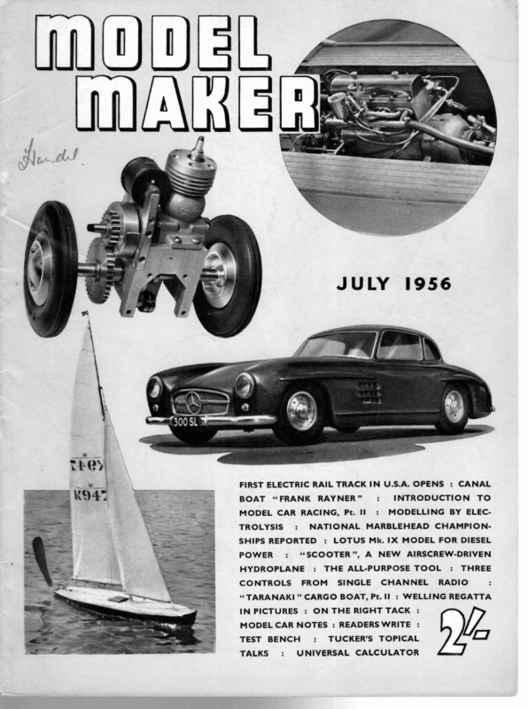
JULY 1956 FIRST ELECTRIC RAIL TRACK IN U.S.A. OPENS : CANAL BOAT “FRANK RAYNER” MODEL CAR RACING, Pt. Il TROLYSIS : : : HYDROPLANE : NEW AIRSCREW-DRIVEN THE ALL-PURPOSE TOOL FROM SINGLE CHANNEL “TARANAKI ” CARGO BOAT, Pt. II IN PICTURES TALKS : : THREE RADIO – : WELLING REGATTA : ON THE RIGHT TACK : MODEL CAR NOTES : READERSWRITE TEST BENCH TO MODELLING BY ELEC- LOTUS Mk. IX MODEL FOR DIESEL “SCOOTER”, A CONTROLS : INTRODUCTION NATIONAL MARBLEHEAD CHAMPION- SHIPS REPORTED POWER : : : TUCKER’S TOPICAL UNIVERSAL CALCULATOR fam |
MODEL 1956 MARBLEHEAD CHAMPIONSHIPS EIGHTEEN ENTRIES GOMPETE AT DOVERCOURT MAY 19-21 Left, Triumph ,local winner and second oldest boat in the race, moved into top place during the first day, was 15 ahead on the second, and won comfortably with a final 11 point lead. Centre, second boat Doris H SECOND was 1954 winner and is a real veteran. Right, third place went to Anemone, another seasoned campaigner THIRD HE 1956 National Championship for Marbleheads was held at Dovercourt over the three days of the Whitsun holiday. The entry of 18 boats was extremely disappointing especially when it is remembered that the 1955 championship yielded a total of 42 competitors. The late withdrawal of the three French entries, owing to the political troubles, was a disappointment for all concerned, but nevertheless the complete absence of any boats representing the South Coast clubs was quite surprising. Under the control of Mr. Mark Fairbrother as O.O.D., sailing commenced on the Saturday morning with a light N.E. wind, and by lunch the oldest yacht entered, Doris H, had gained a four point lead over Emma and Hopalong. In the afternoon the wind backed and became somewhat lighter, and this gave a chance for all the skippers to show their skill. Triumph steadily improved her position and by the end of the day had built up a three point lead over Emma with Doris H lying third. The 342 weather during the day had been fine, but somewhat cold, the skippers and mates making full use of the teas supplied by the lady members of the local club. Sailing commenced at 10 a.m. on the Sunday with an off-sea breeze, which was light and very tricky. The most interesting board of the day was that between Triumph and Doris H, the latter boat gaining all five points by very narrow margins. The weather was quite warm, and the event attracted a number of model yachting enthusiasts from non-competing clubs. By the end of the first round the scores were as follows:—Triumph, 62; Doris H, 57: Gannet, 524; Foxtrot, 52; Scottie, 50; Anemone, 50; Emma, 49; Hopalong, 49; Varuna, 46. Gannet, a new Duck-design boat, proved quite successful, although not good enough for the mate, Mr. D. A. MacDonald, who at lunch-time decided that the sail plan was not correct, borrowed a pair of scissors, and cut off considerable portions of the mainsail. Foxtrot, last year’s winner, proved very strong
JULY, 1956 Monday morning, Doris H and Anemone sailed each other, Anemone winning the beat by a very short distance, and the return run being a dead-heat. In the last heat of the.day however, both yachts gained full points, leaving Doris H second, Anemone third and Gannet Farthest travelled boat was Varuna, which came 300 miles from Ireland. Polythene is obviously difficult over there, hence the ingenious and despincorative ! naker fourth. The championship proved a great success in spite of the poor entry. The Ulster competitor, Mr. Tregenna, stated after the race that he considered that the 600 mile return trip had been well worth while. The sailing throughout the contest called for all the skill that the skippers could muster and at no time could the event have been described as “in the bag” for any particular boat. Most skippers agreed, however, that a little more wind would have made the event more exciting and given some of the heavier boats a better chance. An interesting point to note is that the three top boats bear registration numbers under “500”, proving that, with the right skippers, these designs can still head the list. on the beat, but with the very light airs she did not do so well on the run. All boats suffered with the light winds and consequently many resails occurred. During Sunday afternoon the wind steadily decreased and by the time the fifth heat in the second round took place boats were almost stationary on the pond. This state of affairs caused all sorts of sights to occur (such as Doris H returning over the starting line after she had been half-way up the pond, and then only just losing the board), but it did not last long, and the breeze increased again to give a run and a beat for the last two heats FINAL POSITIONS Triumph Doris H. … Anemone… .. Gannet … Foxtrot Hopalong Nicolette … .. Alexia .. Emma .. Scottie .. Varuna … Zoe … Skuall 1, 2. 3. 4. 5. 6. 7. 8.4 of the day. It was during this period that Triumph gained her real supremacy, only dropping seven points all the afternoon. Results for the leading boats up to the end of the second day were as follows:—Triumph, 95; Hopalong, 80; Anemone, 80; Doris H, 78; ll. 12. 13. 14. 15. 16. 17, 18. Letitia-May . Comet .. Spero Flamingo … Virgo lV … Foxtrot, 76; Gannet, 724. Monday opened with a steady breeze from the N.W., although still light. The main point of interest lay in finding out if Triumph could hold her lead in the face of such seasoned opposition as Foxtrot, Doris H, and Hopalong, all of whom she had to sail. As in the previous round, the Daniels’-designed Doris H gained the full points, she being the only yacht to beat Triumph each way in the contest. A light boat, built by Levison, Triumph has always proved to be equal to the others, and on this day it proved no exception, as she retained her lead of 11 points to win the championship, the first time a national trophy has been held by the” The position for second Dovercourt club. place was not settled until the last board. On Sixth place went to Hopalong also which placed sixth last year, but won MODEL trophy this MAKER earlier season. Meir Skipper behind visible Triumph, oppo- 343 site page 482 224 498 947 927 932 952 718 680 876 979 912 378 945 631 968 728 953 : B. Dale L. Wareham F. Fitzjohn : E. Gorse W.Grint … ee J. Meir S. Nicholls J. Watts H. F. Day H. Death … H. Tregenna H. Penn 3 J. Liddle R. Thorogood P. Mustil K. Roberts G. Brown … H. Howlett … .. .. … .. … .. .. .. … .. … … .. … .. … .. Dovercourt … London Danson Clapham .. Norwich Birmingham… Dovercourt … Danson Danson Southzate mae eny Ulster Birmingham… Southgate ie Southgate Birkenhead … Birkenhead … Birmingham… Dovercourt … 128 17 rs 1034 102 98 97 87 87 87 (‘ 72 7I = 61 59: 54 52
MODEL MAKER steps are taken for waterproofing, there is no objection to the use of hard balsa. After drilling through for the stern tube and fitting the tube in position, the stem and skeg pieces may be glued in their slots and the rudder fitted. The motor mounting is rudimentary, being greatly simplified by the flat floor; it is just a question of glueing packing blocks to the floor to suit the height of the particular unit in use. Naturally, if you propose to tow three barges, a more powerful motor will be necessary than if the tug is to be run solo or loaded with only one barge. When internal details are complete two or three coats of varnish or white lead paint should be flowed inside and on the underside of the deck before attaching the deck. One feature which makes the model very easy is the absence of deck camber, and the amount of sheer required can easily be bent into the 1/16-ply deck without recourse to steaming. The hatch sides must be cut to match the sheer, and they should be pinned in place on the deck while the hatch itself is assembled.. As many hatch formers as desired may be fitted, but it should not be necessary to use more than two formers in the m.v., and three for the barges, in addition of course to the ends. Once the glue has dried on the ply roof panels, the hatch shape will be permanently set. The superstructure is clearly explained on the plan, and should offer no difficulty. Further simplicity is offered in the colour scheme and fittings, especially in respect of. the deck, which does not show planking in the normal way but is covered with a composition and can thus be painted the dull reddish colour of “compo.” The hull exterior is all mid-grey, with the rubbing strips or wales a slightly darker grey. The insides of the bulwarks are the same dull grey; outside they are blask, with white lettering. A dark red paint is used on the super- structure and hatch sides, the hatch top being “tarpaulin green” and the wheelhouse top and funnel mid-grey. Lifebelts are red and white, cowl vents red, and other fittings natural colours or red oxide. The barge (or barges) follows the same order of construction, the only difference being that each end is identical and thus the centre “box” longer, and, of course, the fittings and details are not quite the same. In colour, the chief difference is that the outside of the small bow bulwark is painted white as a visual aid in poor visibility or at night. – PLANE IN YOUR DECK PLANKING ‘THE usual way for making ply decking for suggests B. H. Osborne hole being previously drilled through at an angle greater than 30°. The cutting iron was then sharpened to a cutting width 1/32 in., and inserted in the plane. Provision was made in the body of the plane for a small boxwood wedge to hold the cutting blade steady. The 5/64 in. x 24 in., and a spare piece of boxwood base of the plane was then rebated to the ruler which measured } in. x }in. x 23 in. The depth of an }in. on either side of the cutting “iron” was sharpened with a cutting angle of iron. The remaining tongue of wood was 30°. This was used as a chisel to cut out the 1/32 in. wide, strong enough to withstand the groove in which it lies in the plane—a guide pressures used in normal planing. The plane is used in conjunction with a straight edge. WEDGE XQ SIDE VIEW A simple tool of this nature, which could be easily made by other model makers to make their fie ae decking more realistic, is limited in its use to cutting along straight lines, though no doubt by restrictTCO re CLEARANCE HOLE ing the amount of tongue on the base of the plane a gentle curve FOR SHAVINGS could be obtained. model boats is by lines drawn in pencil or ink. Feeling that a more authentic finish could be achieved, I manufactured a small grooving plane to this end. All that was required was a length of a square section needle file approx. a ~~. ——_— == . —— aa en er | =e TONGUE TTT BOTTOM VIEW
JULY, 1956 STARTING ON THE RIGHT TACK PART FOUR— TUNING UP BY D. A. MACDONALD “THE amount of time and effort involved in tuning up a yacht for maximum performance varies very considerably. Some boats reach their peak performance after a few hours of sailing time—others are still not giving of their best even after a season’s racing. The time taken depends mainly on two factors. One is the amount of care taken on the design and construction—obviously a boat which has faults will take longer to sort out than one which is free of vices. The efficiency of sails and gear enter into this to a large extent. The second important factor is the way in which the tuning-up process is carried out. If this is done systematically and logically it will obviously produce better results in a given time than will haphazard sailing and random guesswork. The final stages of tuning-up will involve the skipper as much as the yacht, because however perfect a craft may be, the skipper must know its behaviour well enough to be sure exactly what effects will result from any change of trim under any kind of sailing conditions. The novice who has just completed a new boat is sure to be anxious to get it on the water as quickly as possible. This urge must be restrained. Before the boat leaves the dockyard it must be checked over most carefully. The action of all the gear must be checked and all sails set up, so as to ensure that all suits and spinnakers can be used to best advantage when required. The boat should be tested in a tank, fully rigged to ensure that it floats on the correct L.W.L. It should not be sailed until the skipper is certain on this point. It should also be put through the process of measuring for conformity with the rating rules. If in any doubt, the owner should call in the club measurer, or other competent person to assist. Many yachts are launched and laboriously tuned up before being submitted for measurement, with the result that if they are found out of rating and have to be altered the whole or at least part of the tuning process has to be done again. Alterations and possibly re- measurement may, of course, have to be done if the tuning-up process reveals the need for such changes, but an extra measuring operation takes far less time than a repetition of the tuning up process. Therefore, the practice of measuring first is a valuable insurance. Assuming the new craft has passed all its ‘‘dry-land”’ (2) tests, she may now be launched on her home water. Most textbooks advise the skipper to choose a warm dry day with a moderate breeze. Unfortunately, in our variable and unpredictable climate, this might mean (3) a very long delay for the man who has other calls on his time, so in practice it is usually a case of making the best of what conditions are available and using each opportunity of sailing to the best effect. Yachts with cloth sails should, however, not be sailed in wet (even damp) or very windy weather until the sails have been fully stretched out. Until the sails are fully stretched the yacht will not trim or handle correctly to windward, so it should be remembered that the later stages of tuning “fon the wind”? should not be attempted until the sails have attained their correct form. The method of stretch- to a jack stay. The halliard is set so that the luff is only gently taut, and the same applies to the outhaul. The kicking strap should also be fairly slack. (4) (5) ing new sails is as follows: (1) Set the jib. Halliard and clew outhaul should be set gently so that there is a minimum of strain on the sail. If there is a jib kicking strap, this should be set so that some rise of the boom is allowed. Set the mainsail. The luff should not be hooked (6) Ensure that all standing rigging is correctly set up A spiral cord lacing should be used on the luff, but left sufficiently slack so that the sail is not pulled in to the mast but allowed to retain the hollow in the luff which it naturally assumes when set up as in (3) above. The yacht is sailed on one or two boards closehauled, and trimmed to sail full full-and-bye, not too high in the wind. It will soon be found that the main halliard can be tightened. When this is done it will be seen that the hollow gap between mast and luff is and perfectly taut. 363
main. To set the main kicking strap, pull the boom down until the leach of the sail is quite taut, and then allow the boom to rise until the clew of the sail lifts by. about gin. for every 10 in. of length on the foot. With the yacht held in an upright position, and pointing so that the wind strikes normally on the sails, set the jib kicking strap (if fitted) or adjust the position of the deck hook on the jib boom, so that the leach of the jib, when viewed from astern, forms a curve parallel with the leach of the mainsail. The rig now consists of two airfoils, virtually parallel in both horizontal and vertical planes, giving a gap or slot of uniform width along its length. The clew outhauls should be adjusted to provide a slight camber (or flow) at the foot of the sail. In Fig. I we see an experienced skipper carrying out this operation of trimming for windward sailing. Note how the yacht is held in the wind—as nearly as possible as if it were sailing, and the skipper sights along the sails from astern, making sure that the sails are in fact lying in parallel curved planes. Note also that the angle of the booms are set in relation to the horses in accordance with the instruction given above, and observe the slight camber imparted to the foot of the mainsail, by adjusting the outhaul. Fig. II shows a nicely trimmed yacht sailing in a very light breeze—the lift of the main and jib booms is perhaps rather more than advised above, but this serves to accentuate my point about the parallel curves on the leach of both main and jib. It is worth considerable care to get this sail trim just right, and a waste of time trying to get the best out of a boat until such a trim can be achieved. When the skipper is completely satisfied that the sail reduced, and the slack in the lacing can be taken up, but without pulling the luff out of its natural curve. The jib halliard can also be taken up (7) (8) (9) trim is correct in every respect for maximum efficiency, the vane steering linkage pin should be removed and the tiller locked central. A very taut tension on the centring line could be used for this purpose, but it must effectively slightly and the outhauls adjusted as necessary. The yacht is again sailed for a time, as in para. (5), and the process of para. (6) repeated. When the sail is fully stretched, the mainsail luff will lie naturally snug to the mast, and it can then be hooked to its jackstay without developing creases, The jib-will have lost any slight creases which appeared when first set up. It is likely that on a second outing the sails will have tended to shrink back slightly, and the lacing may have to be used again, until the sail has prevent any tendency for the rudder to rise or fall when the yacht is heeled. The vane rotor should be set in line with the linkage arm with the feather aft. The vane gear will now take up something like its normal position when sailing, but will not actuate the tiller. The yacht should now be put off, full-and-bye, with a slight imparted way, into a light breeze, and its behaviour noticed very carefully. Normally it will do either of two things: (1) It may continue to sail full-and-bye, but slowly falling off the wind until its course becomes permanently acquired its final shape. The first and most important step in the tuning-up process is to establish the mast position. In the past this has often been a difficult process and, in fact, many yachts had to make considerable use of the adjustable (2) jib spills wind and shakes, whereupon the boat mast arrangements to allow alteration of position and goes “‘into irons’’. rake for various sailing conditions. Better hull balance Whichever happens, the boat should be taken back to the starting point and the process repeated, but sailing on the other tack. The yacht should exactly repeat its previous performance. If it does not (e.g., turns into the wind on one tack and falls off on the other) the yacht is out of lines in some respect, and the rudder should be checked and re-aligned as necessary until the boat behaves (as near as can be judged at this stage) in the and the assistance given by vane steering gears have ns made the mast position less critical, but it is none the less necessary to find the optimum position for windward ——— 3 eS TS = aes sailing in order to derive the maximum efficiency from sails and steering gear. To determine mast position the yacht should be sailed close-hauled, and I recommend that the position be established by sailing on a light breeze, and checked again when sailing close-hauled in a fresh to strong wind. For the first test the mast should be set up in the designed position, with the amount of rake indicated on the design. The standing rigging should be really taut, with particular attention to the jib stay, and the mast should be dead straight, with no tendency to lean to either side. Assuming we have a slight breeze, the jib and main sheets should be set so that the boom angles are in the theoretically correct position for sailing close to the wind. Assuming the yacht is fitted out in accordance with the previous articles in this series, this means that the sheets are set so the boom lies just outside the ends of the horses, the jib being a shade freer than the something more like a reach. It may turn up slowly into the wind, until the same way on both tacks. It is worth repeating these tests a number of times, to be absolutely sure that the behaviour is identical on both tacks, and no further operations should be attempted until this condition is achieved. If the yacht is found to have a general inclination to fall away, and not point up to the wind when correctly trimmed, the mast should be moved aft. If on the other hand the boat goes into irons, or sails so close to the wind that the sails continually spill wind, the mast should be moved forward. The amount of movement required depends on how seriously the yacht is off course and also, of course, on the length of the yacht 364 (Continued on page 371)
JULY, 1956 Readers write… The’ him free to design his own superstructure and fitting elegant arrangements. plastic little The next point I wish to make is one of clarity. walletcontain- double – ended The drawing published is simple, and yet gives all the necessary information that is required, and is not cluttered up with details of parts drawn separately. May I congratulate you on an excellent magazine, B.A. spanners which really caters for the modeller, no matter what ing chrome vanadium line of thought he is. inthe hard-toget model sizes will Addiscombe, Surrey. which be Plans for the Future ? pre- sented to our Dear Sir, Your editorial in the May issue was so interesting and sincere that I felt I must write about it. I think the contents are very well balanced, although my own interest is in radio-controlled boats, I must accept the fact that other readers have differing interest. Regarding the plans you publish, I would say they roughly fall into two categories, the hard chine launches and the bread-and-butter type ship. Looking at the plans available, I would say there is a shortage of the latter, in particular, attractive-looking ships like the Pathfinder, and it doesn’t surprise me that you have had such success with this boat. I’ve no doubt you will find Pateke nearly as popular. The point I am trying to make is that the first thing 95 per cent. of your readers would consider would be the appearance of the model—an attractive boat is attractive to everyone. You also mention M.T.B.’s as being very popular. **Readers Write” D. GEORGE. cor- respondents. Mancunian Model Cars Dear Sir, It is proposed to form a model racing car club in the Manchester area, and if sufficient support is forthcoming, to approach a municipal authority for assistance in obtaining a site. The initial efforts are to be for cable racing, but if numbers and enthusiasm are sufficient, to cater for rail racing at a later date. It would be greatly appreciated if you could men- tion the above in Mopet Maker, and ask any interested car fans to get in touch with me. Yours faithfully, N. REED. 31 Dover Park, Davyhulme, Manchester. Doesn’t this suggest that many of us are interested in Naval craft? When are you going to produce a Motor Patrol boat? Something like the Gay class L. 75 ft. beam 20 ft. would be excellent—scale about iin. to 1 ft. to bring it a little above the usual 3ft. of M.T.B. plans available. To conclude. may I ask why we never see the Destroyer in plan form, this would surely catch the Popular “Pateke”’ Dear Sir, I have just received the copy of the MopEL MAKER in which you have published the plan of the ship Pateke, and you ask for reader’s comments. May I comment that to produce a drawing from photographs to scale, you have my deepest congratulations, as I know only too well how difficult this is, imagination of the more advanced builder. I realise the length would be about 60 ins. to get a reasonable beam, but with an ex-Government motor in, this would give quite a scale speed. especially if the photo of the vessel is at an angle ! Regarding that you have not detailed the superstructure and fittings on the plan, personally I think this to be an excellent scheme; this then leaves the builder to choose what material to use, and so leaves Yours faithfully, G. EXLEy. Cleveleys, Blackpool. = <> ON THE RIGHT TACK (continued from p. 364) itself. A trial movement of } in. should be made and the effect noted. Subsequent movements may be either greater or less as required. The performance to be aimed at, at this stage, should be such that the yacht sails to windward, but so close that the sails are on the point of spilling wind. In fact the sort of performance which two or three degrees of weather helm would be required to correct. It is worth spending quite a lot of time and care achieving this result, since it will ensure that the vane gear, when brought into use, will be operating under its proper conditions—in fact doing just the job it is intended to do, and no more. The mast position obtained in this way will need to be checked at the first opportunity in a fresh breeze. The boom settings will be the same, but the kicking strap will need to be set a shade harder. If the yacht is very accurately balanced, it will sail in the same way with this trim in a stronger wind. Most probably, however, it will go into irons rather more readily. If this tendency is very marked it will be advisable to establish a new optimum mast position for the stronger wind (being careful to mark or record the light wind position). If the two optimum positions are reasonably close together (say within %in. or less for an ‘“‘M”’ class yacht or larger), then a compromise intermediate position may be adopted, and later modified slightly as required in the light of future experience. If the optimum mast positions differ widely (and I have known cases of more than 2 in. difference), the yacht is liable to be troublesome to sail. I hope to give some information later on dealing with awkward cases of this kind. 371
MOOEL Aa UCKER’S THIS TOPICAL advises the streamlining of the skeg and rudder. Now, my friend, Mr. Macdonald, is one of the best skippers in the country, and possibly knows more about vane steering gears than anyone in Britain. His articles have been a mine of most valuable information. Hence I trust he will not object to my querying this single point. Let me first quote what he says on this matter: “To improve rudder efficiency and reduce resistance, the skeg and rudder should be nicely streamlined as 57 ieee TALKS AND THAT \ J S most Model Yachtsmen, not only in_ this country, but throughout the world, will have heard, Mr. Chas. R. Seabrooke was obliged earlier in the year to resign his position as Chairman of the Model Yachting Association. Shortly afterwards, he went into hospital and had a serious operation. All my readers will be glad to hear that he has now recovered and has returned to work. Since the War, Mr. Seabrooke has occupied one arduous post after another in the M.Y.A., as he has been Racing Secretary, Treasurer, Hon. Secretary and Chairman. In all these positions he has given unstinted work for the good of the sport and the Association. In addition, Mr. Seabrooke has been SecretaryTreasurer of the International Model Yacht Racing Union for several years. How he has managed to do all he has done for model yachting, and at the same time earn a living, only he himself can guess. At any rate, persistent and continuous over-work has been a contributory cause to his illness, and under medical advice, he will have to take things somewhat easier in future. Model yachtsmen everywhere will be glad to learn that Mr. Seabrooke feels that he can manage to continue in his post of Secretary-Treasurer of the I.M.Y.R.U. When Mr. O. Steinberger, late Vice-Chairman of the M.Y.A., took over the Chairman’s office, he resigned from his position as appointed Council Member for the H.Q. and Individual Members’ Division. Mr. Seabrooke has taken his place, which gives him a seat on the Council and a vote. May I, on behalf of all model yachtsmen, put on record our gratitude and appreciation of all he has done for the sport. * * Reverting to the remarks about model yachting lakes in my February “Talk,” I feel that in discussing these, one might almost reverse the famous dictum about beer, and say that there are no good lakes in the country, but some are worse than others. Yet do we want the absolutely perfect lake where there are no wind obstructions or hazards of any kind? Or would it prove as dull as a golf course without bunkers? As a designer, I am strongly in favour of the perfect lake where all luck is eliminated, and the premium on the _ skippers’ skill reduced to a minimum, as that would give us true tests of design. On the other hand, would racing then be as interesting and exciting as under less perfect conditions? Discussion on these points is. purely academic, as we are unlikely to get a water where the wind blows uninterruptedly from every quarter. Hence, we have to make the best of the lakes we have, and strive always to persuade local authorities to give us more and better facilities. * * * In the May instalment of his series of articles “Starting on the Right Tack,” Mr. D. A. Macdonald together.” In the days of Braine steering, the skeg was usually joined to the after part of the main fin. Further, in sailing to windward the rudder was locked amidships, and therefore, formed a continuation of the fin and skeg. In such cases, there was a good and obvious reason for carrying the streamlining of the main fin right through to the after trailing edge of the rudder. In fact, I myself usually did this in my designs. With vane steering, the skeg is separated from the main fin. Also the rudder is never locked, and is hardly ever amidships. To windward, the optimum trim for the yacht needs two or three degrees of helm. Now let us briefly consider how a rudder functions. When the rudder is put to port, it interrupts the flow of water through the port garboard angle. This sets up a steering effect which is felt in two ways. The interruption to the flow of water through the port garboard acts as a brake on the side of the boat, and the sveed of the port side is reduced so that the starboard side over-runs it. Likewise, the water pressure engendered on the port side of the rudder pushes the stern up to starboard. The net result is that the head goes to port and the stern to starboard, and our course is altered to port accordingly. How does this affect the streamlining? On the port side, the streamlining is entirely upset by the rudder. To starboard, the streamlining comes to an abrupt end at the rudderpost. Hence, it seems to me that one should keep the thickness of the skeg to the minimum necessary to take the diameter of the rudderpost, and/or as required for strength and rigidity, both depending on the size of the yacht. Of course, one rounds off the forward edge of the skeg to minimise head resistance, and tapers off the rudder-blade to avoid eddies astern. In any case, I cannot see any advantage in making the skeg and rudder any thicker than absolutely necessary, especially as a flat plate has the highest value as lateral resistance, combined with a minimum of head resistance. However, Mr. Macdonald is entitled to his opinion, as I am to mine, and possibly I am wrong. In any case, it cannot make a great deal of difference either way, unless the rudder is locked amidships, when streamlining is highly desirable. * * * A frequent difficulty encountered by owners of new boats is a tendency to broach in heavy slams with a strong quartering wind. In a few cases, this is due to faulty design, but usually it is the skipper’s fault, or lack of tuning up. When broaching is due to bad design, the usual cause is an unbalanced hull. Even in a balanced boat, it can arise from too abruvt a turn round the midship section, resulting in a pot-bellied craft with weak shoulders and quarters. Again, if the Continued on page 376 374
ry CASE ZZ Sad TO IS ONE SIDE OF COIL LOWER FREQUENCY WEIGHT ARM, PULSING Fig2 especially if electric propulsion is used. The completed chassis (illustrated) is only 6in. x 12in. and if required can be made much smaller. I shall be fitting this gear in a 48in. tanker so space is no problem. I include a 0.5 ma. meter because it makes adjustments at the pond side much easier, and also 1 have fitted a pot. in series with the 1,000 ohm relays for easy adjustment. All experimental work was carried out in a Veron Marlin using a 12 v. ex.-govt. blower motor. The receiver is Doug. Bolton’s design and gives about 3 ma. current change. The Mallory vibrators are easily obtained and altered, and cost about 6s. RELAY | returned to a 50/50 ratio unless a complicated balance pot. is used on the _ steering mechanism.) There is only one disadvantage with this present system, because when the Tx. gives say each. Instead of using a stepper relay one can use an ordinary P.O. relay with a pair of make and a pair of break contacts. The energising current for the relay passes through the break contacts, which are closed, causing the relay to pull in; this breaks the circuit and the relay drops out again, thus completing the circuit, and so on. If one already has a Tx. and an Rx. it should only cost about £4-£5 to build the complete outfit, which I think is well worth the time and money spent, considering that the result obtained compares with 3-reed control. As there can be several variations of this system, I should be interested to hear how full mark, the first sensitive relay will drop out and the condenser will be discharging maximum current, and both 1,000 ohm relays will pull in, This can be conveniently avoided by controlling the main motor from. slightly delayed slave relays worked by the 1,000 ohm relays. (In any case the time taken for the rudder to travel from left to right should only be about 4-5 secs. and should the main motor be stopped it would not be noticed.) I have experimented with pulse transformers, but find this present system gives more accurate control, is easier to construct and is inexpensive. The equipment is not unduly heavy, but requires a hull of at least 36in. length, anyone else has got on.


