- Title. Author. Summary

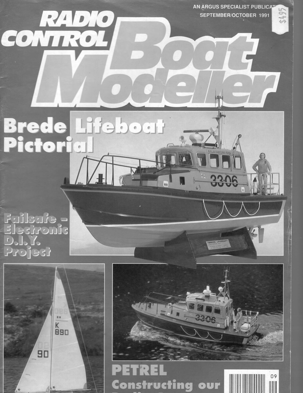
AN ARGUS SPECIALIST PUBLIC me W a ee mnie a SEPTEMBER/OCTOBER 1991 PETREL| | | Constructing our
The author’s model, named Bee, on launch day, with the mainsail designed for heavier winds made by Martin — Roberts of Housemartin Sails. Alan Bright constructs John Lewis’ Radio 6 Metre published in Jan/Feb 1991 issue he publication in Radio Control Boat Modeller (Jan/ Feb. edition) of the Petrel design by John Lewis, has coincided with a resurgence of interest in this class of model yachting which is long overdue, but | must admit to some bias on this point! (The plan is available from Radio Control Boat Modeller Plans Service, Argus House, Boundary Way, Hemel Hempstead, Herts, HP2 7ST. Please quote Plan Number BM1445. Price is £3.60 including post and packing. The lines and profile are drawn half full size; the sail plan is 1/8th full size. Model whois still learning. If you want to see what a true artist/craftsman is capable of, then John Gale’s yachts stand out, but do not be put off if your results do not reach such levels, because most of us are mere mortals! wide chipboard of the type sold in DIY stores for shelving, and run a length of 2 x 1 softwood placed vertically down the length of the board on both edges to resist any tendency to warp and provide the necessary stiffness, see photo. Next mark the section spacings on the top surface of the base board using a metal edged square and a Stanley length is 57in overall. Ed.) Having built a Revival design by Graham Bantock for last year’s Nationals and planked the hull of another Lewis design Tern for Paul Heys, a fellow club member, | was keen to build a different design for the coming Nationals and match racing series. The Petrel design has to my mind the two main ingredients for any boat, ie., attractive lines and that certain something to make me want to build and own one, so the decision having been made the next step of actually constructing the boat was comparatively easy, as | hope to prove. My aim in building was to produce a boat that would stand the rigours of a competitive racing life, possibly for several years, and constructed to a standard of finish that | could live with. | hasten to add that | am an average modeller September/October 1991 A proud moment for the builder as designer John Lewis casts an approving eye over the completed model while Vic Bellerson carries out skin girth measurements. Making a Start The first task is the construction of a building jig and it is essential that this is constructed carefully and reasonably robustly to avoid any distortion in construction and thereby ruin all your hard work. For a building board use a length of 6in knife or similar, and then run a pencil along the resultant groove to emphasise the station line for easier visibility when setting up the sections. Finally mark a centre line down the length of the building board. A marking gauge is ideal for this task if you have one. 25
It is now necessary to transfer all the hull sections on to 4 or 5 mm datum, and fix the paper with a couple of small pieces of masking plywood, which must be accurately carried out for any boat if the finished model is to do justice to tape to ensure there can be no movement whilst transferring the lines. Now trace all the left hand/ the original designer’s concept, but especially so in the case of the 6m class where girth measurements etc. are an integral part of the stern body sections using a sharp pencil, but do not make any allowance for hull planking at this measurement and rating process. stage. As well as the section outline, | also transfer the position The method | now use, although of the L.W.L. for a reason that will A narrow enough to deal with the curves encountered on most boats of this class. Now open up a pair of SECTION OF PLANK WITH NO ‘HARD’ SPOT. (NOTE ANGLE SHOWN ON DRG. GREATLY EXAGGERATED) LOWER EDGE somewhat tedious, if carried out with reasonable care will virtually guarantee the lines are accurately transferred into a building jig. Transferring the Lines Ensure the drawing is laid flat, especially in the area of the full-size body sections. Incidentally, if requested when ordering your plans, the A.S.P. will appear on is a great any tendency to distort between sections, helping to produce a good glue line, whilst the extra width requires fewer planks but is still ENSURE TAPER RUNS SMOOTHLY INTO MIDDLE a a APPROX. 2ft planking dimensions to be 4mm thick x 12mm wide. The slightly extra thickness appears to reduce mailing department at ensure that no fold lines the body sections, which help at this stage. BEVEL TO ENSURE A TIGHT SEAM become apparent later. Remove the tracing paper and fold carefully down the marked centre-line; now trace through the outlined half-body section, SO upon opening out the paper you are presented with exact full size sections for one half of the boat, ie: the stern sections. It is now necessary to repeat the process for the right hand/bow sections on a fresh piece of tracing paper. The next stage is to transfer each individual body section onto a WITHOUT BEVEL, GAP WILL BE EVIDENT, ESPECIALLY WHERE TIGHT RADII ARE ENCOUNTERED. First of all extend each section a common building datum line, which must be parallel to the water-line. | find a line approximately three inches above the sheer line at mid section is about right. It is interesting to note here that whereas the L.W.L. is probably the most important datum line to the designer (and dare | say it the measurer!), the builder will be far more interested in the accuracy of the building datum line in relation to the L.W.L. because this is his main reference point. from the sheer line to piece of thin card using a sharp pencil and carbon paper. Having done this cut out each section so you end up with a full-size template for each hull section. Hopefully by now you will have laid in your stock of hull planking. | obtained the planking for this model from Sails Etc. Alternatively a good compasses to the required finished planking width, which in my case was 3mm, and using the edge of the card template as a guide for the compass point, run the compass round the body sections from sheer to sheer, so ensuring a very accurate reduction for the hull planking. Finally cut the small 3mm strip away to give you the finished template. This might appear to be a lot of work to produce a set of accurate hull templates but it can in fact be completed in just two pleasant evenings without difficulty and at this stage | also make full size templates for the rudder, fin and bow profile which helps building progress more rapidly later on. Now transfer the body sections onto 4mm or 5mm plywood; scrap can be obtained quite cheaply from most DIY or timber merchants. When drawing out the hull sections also mark onto the plywood the L.W.L. and centre-line plus the slot required for the keel/backbone assembly. The backbone was laminated from three lengths of planking, however towards the aft water-line ending additional laminations are required to accommodate the skeg/bustle arrangement. Note detail on photographs of building jig The Backbone by 10mm wide, so allowing 0.5mm Cut out the plywood sections” using a fret-saw if you have one or if not a coping saw will suffice. If you cut just outside the marked line you can run a file or glasspaper over the edge to ensure a perfect finish results. Do not however go for sanding | need to allow 3mm for below the line. Remember what | have already stated about skin girth Lay a sheet of tracing paper over the body sections including the the finished planking thickness. Incidentally, having now planked four six-metre hulls in the past twelve months and already working approximately 1in square to the extended area to the building on a fifth, | believe the ideal lower edge (building datum), on the local sawmill will usually oblige. The planking | used is 3.5mm thick measurements, etc. Screw softwood battens
method, which with reasonable care will enable the avenge modeller to complete a hull worthy of the class. First of all if you intend having a varnished hull or as | prefer varnished topsides, and a paint finish below the water-line, you will find colour matching the planks so that any colour differences occur gradually, will achieve a pleasing finish without much difficulty. Alternatively you may wish to try a striped effect with the planks varying to different degrees from the adjacent plank. This | find very attractive but it will show any defects in your planking more readily so be warned! The L.W.L. marked on the sections will enable you to determine how many planks are required for the topsides, bearing in mind that the overhangs fore and aft require more planks to cover than the midship section. The method | use for tapering the planks has now been proven for several hulls to different designs ie: Revival by Graham Bantock, Tern and Petrel designs by John Lewis, and is relatively quick and straightforward without the need to divide each section by the number of planks (in this case 30 per side) which is the traditional method. Select your plank and cut this to length allowing approximately an inch extra. It is necessary, starting unmarked face of each section. Next mount the sections to the previously constructed building board by screwing from underneath through pre-drilled and countersunk holes in the building board into the battens attached to the hull sections. Ensure that the centre-line drawn on each section lines up accurately with the centre-line drawn on the building board, (this was why the batten was screwed onto the other face). The use of a square will also help in checking the vertical alignment of each section, but | find that standing back a couple of paces and looking down the length of the hull will usually show if centre-lines are misaligned, especially from one section to another. All the forward sections must be placed facing towards the bow and the aft sections facing the stern, see photo, as this will reduce the requirement for any bevelling. To stop the planking from sticking to the sections run a candle over the edges or cover with Sellotape. Having completed the jig you are now ready to commence hull construction. First laminate the backbone using three planks; the use of a template showing the bow profile assists in ensuring the correct curve is maintained. Make sure that you allow for a capping September/October 1991 piece to be laminated to the bow plank endings, ensuring the final L.O.A. is exactly 57 inches as specified. The backbone will require additional planks either side of the fin root location, extending slightly longer, approximately two inches each end. The main backbone will be cut away eventually to take the fin. The stern overhang part of the backbone, see photo, is in fact a separate piece joined to the main backbone by several laminations of planking material. This rear backbone section will require an additional plank either side let into the upright sections to effectively treble the width of the backbone. This enables the plank ends to have an adequate glue surface in this important area. Onto this aft backbone section glue a piece of planking down the centre-line, end on, to which the tapered plank ends will eventually butt, see photo. Planking With the backbone completed you are now ready to commence planking, which is the one area that worries people building a timber planked boat for the first time. By trial and error, on building several hulls of this class, | have found a relatively easy and straightforward about two feet from each end, to taper the planking to half its width at each end. Using a pair of dividers set at 5mm in my case or at 6mm if your planking is 12mm wide, mark each plank ending, then using a 2 ft ruler or straight piece of wood draw a pencil line as shown in the drawing. Using a small sharp plane, (I use a David razor plane), plane the plank ends down to the pencil line ensuring a fair even curve results. This operation can be carried out for 4-6 planks at a time but do not be tempted to complete a larger quantity in one batch, as the planking will gradually become shorter as you progress, and once the excess length has been cut off they will of course not be the same width at the ends. Before fitting to the jig it is necessary to bevel the lower edge of each plank to ensure it sits flat to the top edge of the plank below. This is not of course required on the first pair of planks to be fitted which is at the sheer-line, as a flat surface is required to which the deck will eventually be bonded. | have tried to show in the drawing the reason for this bevelling, which looks harder than it in fact is, and after a few planks you will find it becomes a lot easier. 27
Adhesives One point here worth mentioning is the selection of a suitable glue. My own choice has always been Cascamite as | am familiar with its properties and know its weak points, the main one being that when dry it is fairly brittle which makes sanding down more difficult. Another glue regularly used is Aerolite 306 which is similar to Cascamite, but uses a separate hardener. The big plus for both these glues is that they do have the ability to fill small gaps in glue lines, and whilst this is no excuse for poor planking it can be useful, especially if this is your first attempt. | have however recently seen a one-metre hull, cedar planked (by your correspondent Bill Green), where the glue used is the white p.v.a. type available in a blue plastic dispenser of the waterresistant variety. This glue has the considerable advantage of ease of use, quick drying and easy to sand down but does not have any gap filling properties. Provided the hull is thoroughly coated in epoxy inside and out, the glue should be more than adequate with regards to its water resistance. Because of these advantages | would not consider using cedar planking without an epoxy coating. | intend trying out a pva glue on the next six-metre! When using epoxy as a coating ensure the type used will give adequate saturation of the timber. These are marketed by several manufacturers such as West Systems and SP Products. One final word of caution in using all epoxy based products, ensure you follow the manufacturers instructions for safe use and handling. After spreading your chosen glue along the top of the preceding plank, fit the next plank onto the jig using veneer pins, which are a finer gauge than the more common panel pins. If necessary, to achieve a good join pull the plank down onto the one below using elastic bands or Sellotape, which will of course have to be removed before fitting the next plank. As planking proceeds it is necessary to butt the planking onto the backbone at the stern, see method to fit this was to stand three suitable lengths of planking in water till pliable, then wrap them round the bow profile, holding them temporarily in place with Sellotape. When the planking has dried out remove from the hull and they will have retained most of the necessary curvature. Now laminate into place with temporary pins in the normal way. Incidentally, make the capping piece of sufficient length that it merges into the hull below the water-line, as it not only gives a neat finish to the plank endings but protects the main planking in the event of an unfortunate bow-on collision. Finally remove any veneer pins remaining in the hull and fill the holes with a plastic wood filler. | find ‘Joy’ brand in ‘Teak’ finish matches very closely to most cedar. photograph. The bow planking is merely trimmed off later ready to accept a capping piece, see photo. Before competing the final few planks ensure that the slot has been cut out of the backbone to accept With this rather tedious task the fin, again see photos. completed sand the hull down using a fairly coarse glasspaper as this tends to clog less, ensuring you do not inadvertently create any hollows in the hull. Refill any pin holes that require filling before giving the hull Capping Piece to ensure any stray glue is not left With the planking completed it is necessary to trim the bow and plane a flat surface to accept the capping piece. | found the easiest a final sanding and close inspection in the surface pores of the timber. At this stage if you have not already done so shape the skeg/bustle to the required section. Coating One small tip before coating the hull, ensure all the wood dust is removed from the timber. | go over the hull thoroughly with a cylinder vacuum cleaner fitted with a small round brush. The removal of the dust from the timber pores will almost instantly give a lustre and bring life to your planking which will show the grain to better effect. Finally coat the entire hull with epoxy resin which will not only ensure the timber is impervious to water, but it also adds considerably to its strength and resistance to those inevitable knocks that occur, either in transport or on the water in competition. With the epoxy dry, the entire hull can be thoroughly flatted down with medium grade wet and dry, Ensure you use plenty of water in this operation to reduce the clogging effect of the epoxy. Before removing the hull from the jig there are a couple of items still to fit, which are best carried out prior to removal. Fin The first task is to laminate and fit the fin. You can either make your fin as in diagram ‘A’, which is relatively simple to produce and used with success in my previous | .
Photo 1; the bow planking is relatively easy compared to the stern. Note curve of backbone at the stem. Photo 2; planking progressing well. Note slot to accept fin in station 5 is just visible. Photo 3; the planked hull finished and awaiting its first coat of epoxy. Note the run of planking. Photo 4; hull with fin fitted and painted up to the 1w1. Note fairing of stern, just visible. Photo 5; all deck beams installed and notched into inwales, bonding with epoxy and coloidial silica. The beams were finally cleaned up and faired prior to fitting the deck. six-metre, hence the slot down to deck level in section 5, see photo. This time, however, after seeing Paul Keys’ boat | decided to adopt the same approach as him which keeps the interior of the boat as clear as possible, as shown in ad diagram ‘B’. The fin was laminated from two pieces of 10mm x 6 inch wide obechi, with the grain reversed to make a block 20 mm thick, which is the narrowest chord thickness of the fin at the root section where it enters the hull — your slot in the hull needs to be 20mm wide. To this was laminated one extra piece 10mm thick, each side where the fin protrudes below the hull, to allow for the extra chord thickness of the fin at the lower edge, (see plan). Before going any further drill a hole to take the 6mm stainless steel studding used to attach the ballast keel. Take care to ensure this is drilled September/October 1991 on the centre-line and is vertical; ideally it should also be in line with the centre of buoyancy and centre of gravity as marked on the drawing. Now shape to the correct profile, checking the original plan which is fairly easy with obechi using a sharp plane, followed by a file and/or glasspaper. Do not be tempted to experiment with fin shapes and dimensions unless you really know what you are doing and realise the consequences of your actions! The designer will have taken into account the fin profile etc., in his displacement calculations when arriving at the correct rating for the design, so any alteration by the builder could upset these important factors as well as the positioning of the sail plan. | decided on an additional fairing of the skeg/bustle into the hull using a fillet made up of epoxy and a 50/ 50 mixture of micro-balloons and coloidial Silica to ease the final sanding down operation. This advice was given to me by lan Cole of Sails Etc., who is always willing to share his wealth of knowledge in the use of epoxy resins, and this no doubt saved me a lot of hard work at this stage. The fairing in of the skeg in this way gives a pleasing flow to the hull lines where they meet the skeg forward of the rudder. Rudder Tube With the fin epoxy coated and bonded into place, drill out the hole for the rudder tube and epoxy into position ensuring that this is correctly aligned in relation to the centre-line of the hull and fin. Finally | paint to the water-line prior to removal of the hull from the jig as this is easier with the hull rigidly held in a level attitude. You can now carefully remove the hull from the jig by unscrewing the sections; you did attach them from underneath didn’t you?. A few taps will remove any sections that might be stuck with stray glue and you are now ready for the final fitting out process. Fitting Out With the removal of the hull from the jig, work can now begin on the 29
final fitting out stage, which although straightforward always tends to take longer than one Costings expects. metre, but eventually decided that this would be unfair due to my own preferences on fittings, etc.; and there are several ways of completing this class of boat with many people no doubt able to produce their own fittings/sails etc. at a further saving in cost. Here however is an analysis of the cost, in £ sterling, | incurred in constructing the hull ready to accept all the deck hardware etc. The first job is to install the inwales, which is easily accomplished using a couple of the remaining planks and plenty of clothes pegs. At this stage insert a couple of temporary beams to stop the hull from distorting. With the inwales inserted the inside of the hull can be cleaned up and the fin reinforcement fitted, see diagram B. | now decided to epoxy coat and line the entire inside of the hull with a lightweight glass cloth. | had intended to list here a complete costing of my own six- a colour scheme of your choice. With the hull completed it now remains to attach all the deck hardware and complete the rig, (consult rule book). A standard 2channel radio installation is still the most popular amongst most of the skippers in this class, see photo. Testing You are ready for an initial floatation test. This can be carried out in the bath with a compensating weight placed on deck for the absent rig and sails. First attach the Whilst it is true that this is not entirely necessary it is still advisable to reinforce the hull with approximately 1 inch wide glass tape at each section, plus local reinforcement around the fin root/ garboard area. Incidentally, the weight of the hull and fin when removed from the jig was 2 lb 8 oz; after fitting inwales and lining the entire hull with glass and epoxy the finished hull weight was 3lb 20z which | regard as acceptable for a displacement design, and the boat should give years of trouble free enjoyment. Deck Beams | decided on a traditional hatch arrangement with all the radio equipment below decks on a removable plate, and the receiver in a radio pot also beneath the hatch. After deciding on the sheeting arrangement and the location of all the necessary fittings, the deck beams can be installed by notching into the inwales. All the deck beams were constructed from three laminations of cedar planking; this has the advantage of strength and lightness plus all those odd pieces remaining after planking can be put to good use. Transom The transom was now fitted by glueing on a small block of cedar, and than shaping to fit whilst actually on the boat. An alternative method would be to let in the transom inside the planking, but having looked at several transoms | decided on the approach | finally adopted which gives a nice shapely transom as shown on the original drawing. At this stage | also laminated the rudder using the template already made out to give the required profile. At this point it might be interesting to discuss the important factor of cost; with such a project as this we need to be sure that the boat we build and sail gives value for money. (Note:- Where suppliers are quoted, please check current prices. 12mm x 4mm planking now available from K Butler at competitive prices). Perhaps the most convincing argument | can use with regards to cost is that my own six metre was completed to the standard shown in the photographs complete with two excellent suits of panelled sails by Martin Roberts of ‘Housemartin Sails’, excluding winch and radio, for a total cost of £225 plus of course many pleasant hours in construction. With all the deck beams in place these can then be epoxy coated on all except the top surface, also at this stage the mast step should be fitted as this is a lot easier minus the deck. Deck Before fitting the deck run a strip of masking tape around the hull at deck level. This serves the dual purpose of keeping any excess glue off the hull and you can mark the position of all the deck beams so you know where to make the holes for hatches and fittings! The decking | used was a piece of ‘Decamel’ which is very like Formica but a lot thinner and consequently lighter. The deck should be bonded on with a view to subsequent removal, in the hopefully distant future, and as such ‘Thixofix’ is an excellent adhesive. With the deck in place and all the hatches cut out, the hull can be painted/varnished to unfinished lead ballast, (remember the total minimum displacement of the boat including rig is 26.58 Ibs). The ballast position and/or weight should be adjusted to ensure the boat floats exactly to its designed water-line without any heel to port or starboard. Use a small spirit level to check this. With this accomplished | would advise any builder to have the boat officially measured before permanently attaching the ballast keel and painting. With the boat measured (using a borrowed set of sails) and now the proud possessor of a valid certificate, the sails can be ordered from your favourite sailmaker to the exact dimensions allowed after measurement. Finally those readers who may be interested can follow the progress of K890, Bee, competing in the now extensive 6 Metre racing calendar. However well she does will largely be down to her skipper’s ability or lack of it!, but | am certain that in the Petrel design John Lewis has yet again produced an excellent ‘classic’ in the modern sense, and | hope this article will prompt many more modellers to have a go at building and sailing a great class enjoyed by an equally great bunch of skippers.
A typical close start at the RM Nationals with Alistair Law (68) trying to elbow Lindsey Weall (90) over early while Phil Playle (97) is about to squeeze Andy Kissick (150) up a little. nce again the Spring Bank Holiday at the end of May saw the running of the MYA Radio Marblehead National Championship. Hosts this year were the Cotswold Sailing Club at their lake in the Water Park near South Cerney, just outside Cirencester. A slightly lower entry than has been seen in some previous years included 6 from France and one from New Zealand, though the latter was unable to start. As the eventual champion pointed out during his acceptance speech, this was the first truly British National Championship for RMs with entries from the newly formed Scottish District. Of the fifty eight entries only fifty four came to the line following Race Officer Martin Mickleburgh’s extensive and sometimes amusing Saturday morning briefing. A great deal of work had been done by event secretary Roger Neeve and his clubmates to make this a championship that would compare favourably with those that | have described over the last two or three years. Although the wind contrived to take the gloss off the sailing part of proceedings the rest of the event ran smoothly and several competitors commented that there now appears to be a noticeable decrease in the animosity and aggravation that has sometimes been associated with RM Nationals and Ranking races in recent years. The way in which this meeting was organised must have had an influence on such matters. The Weall family getting themselves set up for a successful gybe mark. Nick (88) has an overlap on Messrs Cleave, Bantock and Servella. Lindsey (90) is trying hard to maintain an inside position over Frenchman Remi Bres (42). September/October 1991 WITH MIKE KEMP YACHTING The results of two national Championships are reviewed this time, they could hardly have been more different — one had a large entry, sun, sponsored support, and multi-person organisation — the other had a small entry, rain, and was run on a shoestring by very few. In my opinion they had one common element, good racing.
The Cotswold Club is one of the few multi-discipline sailing clubs around which includes a Radio Yacht section. Although equipped with a substantial clubhouse they do not have permanent model yacht storage like the well- established clubs that have hosted this event in the last few years. Suitable temporary accommodation was provided in the form of two ‘half containers’ for yachts, mobile toilets for you-know-who, and mobile offices for the scorer and jury. Such facilities are beyond the finances of such a small entry, even with the elevated entry fee imposed by the MYA. Thus it was fortunate that a major sponsor, the Chelsea Building Society, came to the aid of the event and provided us with what proved to be a very acceptable set of facilities which also included tables, chairs, and only one Launching Techniques 1. Gilles Vuillemin uses a gentle tou ch to float his newly completed Flash to Guy Lordat’s design. slightly less effective spectator seating in the form of straw bales. With the aid of this support the club also was able to provide a nice selection of ‘pick your own’ prizes for the top ten. Racing started only slightly later than scheduled in the programme and saw us all take part in three, four heat, seeding races. One assumes that these were drawn randomly but by a masterpiece of scheduling no one had to change frequencies throughout the whole seeding period. There were also those of us who were fortunate enough not to meet some of the potential ‘top shots’ during this part of the meeting. Martin had warned us that he was aware that the forecast was for wind from just about the worst possible direction for this lake — how many times is it that | have written those words | wonder? Despite this it was his plan to try and ensure that racing continued as quickly as possible, even if it did mean that the course would not always be set at the best angle to the wind. With the wind off the bank from which we were sailing Launching Techniques 2. Dave Potter adopts a starting block position as his yacht speeds away from the landing stage. and swinging up to forty five degrees in either direction there were times when it seemed that there was only one place to be at the start, and only one course to take afterwards. Despite this people did try different routes and sometimes they paid off as the wind went up and down, and backwards and forwards. There were also times when some of the yachts seemed significantly slower than those around them, an indication that there was weed about, though yachts being recovered only showed small traces of this delaying medium. By shortly after two o’clock we had completed our ‘sorting out’ session and racing could begin in earnest. The first ‘A’ fleet contained the inevitable Graham Bantock, two father & son combinations — the Stollery and the Dicks families — Martin Roberts; two Frenchmen were in there also, Guy Lordat and Francois Beaupain were in eighth and tenth places after seeding. Displacing others to ‘B’ fleet were the likes of Dave Potter, Mike Weston, and Robert Brown; even yours truly managed to get in there for one race — but | was soon to blot my copy-book and sink to the depths of despair, and ‘D’ fleet! Roger Stollery came home first in this top fleet, he was chased in by Francois Beaupain in this, the last of the fourth actual race. Just in case you are Launching Techniques 3. This merry matelot (straight from Gilbert and Sullivan?) adopts an elegant pose as his yacht heads off for the water. Oh! by the way, this is Tim Townsend. confused by all this | should point out that, once the seeding races are eventual champion and his close half days of the meeting with the completed, the meeting shifts into contenders providing the finale of the opposite gear and the heats are run in ‘D’, ‘C’, ‘B’, and ‘A’ order. As a result, regatta. with very few exceptions, this order was despite the vagaries of the shifty and generally light winds which meant some followed for the remaining two and a Racing continued at a steady pace
rather odd and processional courses at times. There were few incidents with what was probably a higher proportion of mark touches, almost certainly as a result of some difficult buoy placements in an attempt to get a good course. Starts were somewhat predictable with most getting away to a reasonable first leg, position at the ‘right’ end being all important. Sunday morning found us ready to go with race seven which started slightly later than planned to allow those staying locally to take their breakfast at the convenience of the Hotel. Obviously a group of early rising yachters was too The last day’s racing resumed just before ten o’clock and moved along at a fair pace in an attempt to pack in as many races as possible before the target finish time. It was an impossible task to reach enough races to allow three discards so racing ceased at the end of number nineteen. As the run down to the finish began it became clearer that the championship was going down Essex way again. Consistency proved to be the key yet again, with our new champion Graham Bantock being the only skipper to stay in A fleet throughout the meeting after initial seeding. The French threat faded away The simple swing rig? This example used by Frenchman Remi Bres has more standing rigging than many conventional rigs. Officer Martin had delegated this responsibility to Brian for the whole meeting and this last session tested his powers to their limit. The whole incident revolved around the wing mark and saw an alarming demonstration of the speed with which incidents develop and occur in our form of yachting. Five or six known yachts were involved and although evidence taken from a capable observer, and those skippers who could be identified was roughly in accord there was no conclusive damning story. One yacht had executed two turns in an attempt to exonerate any blame that might have been laid against it. After coming to a decision not to place any further blame on anyone else involved the Chairman and the rest of us involved were offered the chance to see the incident through the eye of a video camera. Even watching the whole incident in frame by frame slow motion it was difficult to see where any blame should rest. What was crystal clear was the amazing short duration of the whole period from the time when those involved entered the four boat circle to their exit from the mark. All the while this was going on our own One Armed Bandit, lan Taylor, was pacing the floor in his control caravan waiting to punch in the final results. Poor lan had been whipped off to hospital in the middle of Saturday night for treatment to a damaged left shoulder area and spent the rest of the weekend semi-‘armless. At least he was in less pain during Sunday and Monday. In addition to the traditional top ten awards presentations were made to the best ‘Team Of Three’ which, Built for reliability. Simple almost to extreme is Sun 2 by Gilles Vuillemin. Attractively planked in multi-colour wood. much for this establishment despite their briefing, as Martin put it, to leave anything red and glowing plugged in! With little change in the wind conditions racing continued much as it had the previous day. The lack of start line incidents was probably due to the light conditions; this feeling was confirmed at the start of race 9 C when we had the first general recall. This followed a sudden and not very well predicted increase in wind force with the result that getting on for half the fleet found themselves rapidly running out of line during the last few seconds of the countdown. There was an almighty pile up at the Port end of the line with little chance of the observers and/or the start line judge accurately determining who was to blame and all those that were over early. By about lunch time on Sunday we had reached race ten. Two races later just after four o’clock, at the end of twelve, there was a significant delay brought about more by protests from observers than from other skippers. These took some time to sort out, so much that racing did not resume until 5.20pm; thus race thirteen was the last of the second day. September/October 1991 during the middle of the meeting, though Francois Beaupain slotted his ‘Flash’ named Nicotine between Graham and third place skipper Martin Roberts. Designer of the ‘Flash’, Guy Lordat, also made it into the top ten just below newcomer to this country Remi Bres who was also sailing a yacht to Guy’s design. Prize giving followed the usual pattern though only after a tortuous protest meeting chaired by Brian Corley. Race Wide variety of casual gear evident i during the strengthening wind on Da of the RM Nats. A public gear failure on Dave Wilkinson’s Topquark as the mast step parts company with the hull. mysteriously for a randomly selected group, was all French! Additionally, courtesy of Graham Bantock, a special award was made to those competitors over 65: two of those owning up to qualifying for this were also French, the other was our own irrepressible Ken Clements from the Cleveland Club.
with the choosing of two random fleets by ‘neutral’ parties – some of the accompanying ladies. Three seeding races were sailed in two heats with the fleets being redrawn for each race. It quickly became obvious that, although the expected skippers were beginning to dominate, racing would be close with places changing throughout each heat and little evidence of the ‘processions’ that might have been predicted with such small fleets. The swinging and varying wind meant that there was no predictably obvious route from the start; although there remained an element of Port tack bias on the line, a | . Martin Roberts makes his thankyou speech for third place. tempting enough for a few to try starting Guy Lordat had good reason to smile this year with three of his designs in the top ten. Guy came in 7th. at the near end. This led to the as inevitable Port/Starboard incidents was if one racing hotted up. However, this end of the successful in crossing line with good bank, claiming quickly getting was in a fairly oy boat speed towards the water to tack away and away on to Port tack, one commanding position up the first leg of the course. Four skippers succeeded in collecting at least one first place during this series: two managed to win two each. After temporarily discarding their worst score, a third for each, these two — Dave Mann and myself — were tying for first place. Following in third place was Roger Neeve, the only other skipper to maintain the same position right through to the finish of the championship. In fourth place was a skipper beginning to show the result of some serious study of radio racing skills; Bill Green was having an excellent start to the weekend. After an early break for lunch during which the necessary calculations were completed to confirm the heats for ‘fleet racing’ Simon got us racing again. Nearly the new MYA RM Champion, Francois Beaupain sailed into second place. ee 1991 RM Nationals — Top Fifteen Yacht Club . een Ist2nd Grane aco Franc ieaa 3rd 4th bth 6th 7th 8th gth 10th 11th 12th page Cc ret le Phil ! Gras ay Larue atike Weston t ae Cleave Aaa Stetiety aN Taner n ance “ie Dicks D1 13th Mark 15th Robert Brown 14th Nick Weall ford esous Eorares Clapham Chelmsford Lavanou eet ar 542 Fast See Flash Seer Birkenhead CN Viry Swanley Ryde Guildford Fleetwood Chichester Clapham Gosport Edinburgh Radio 6 Metre Nationals Fourteen of the growing group of Radio 6 Metre skippers gathered at the southern end of Lake Windermere on Saturday morning June 8th. Race Officer No.1, Simon Redford laid a largish course to face a basically South South Westerly wind of variable force which caused some skippers to change down from their absolute maximum, and then back up again as the day progressed. a – 42.7 Flash — F2400 K4347 be pitas a K4534 Slick 4444 Enigma K4239 TOP K4291 Enigma K4328 Enigma K4366 Mystick kao until late afternoon. Simon kept things rolling along at a steady pace with little 2 | Eleven races were completed on Saturday as the forecast rain held off 98 Enigma es K361 Enigma 101.1 111.7 118.4 431.1 134.7 437 175.4 181.7 201.7 203.1 208.7 Initially it was intended to use lan Taylor’s ‘System Six’ to provide a small fleet system based on heat sizes of six yachts each. Because of one last minute drop out it was decided to use two fleets of seven and IRCYRS ‘90 to the base of eight. Thus it only took from around 10.15 until about 12 noon to complete three randomly selected seeding races. This, by now traditional, start to fleet race meetings got rolling between heats, finishing sailing at delay round 5 o’clock. heldt, ndentpursui correspohot : At this A yourtik bs lead ee oes Mann The eur atk f antiti phad completed an afternoon of very close racing with little between us in any one race though Dave was inexplicably starting to fade out of contention. Next down the list was Paul Heys with the trio of Mike Ewart, Alan Bright, and Bill Green battling for the middle order. Jack Day was showing the occasional flash of brilliance to hold ninth place ahead of local skipper Richard Pierce who was but two points ahead of Birkenhead member, Peter Knowles. Another newcomer to Radio sixes, Jim Macdonald, followed with George Williams not having a very successful day though staying ahead of last place skipper, Matt Carrington-Sykes from North Wales, sailing one of the prettier yachts of the meeting — a ‘Glenrosa’ design named Black Prince. As the rain began to fall in earnest the assembled group split to find their overnight, and in one or two cases week’s holiday, accommodation. With such a small entry, split into groups of ‘family’ and single attendants, it is very difficult to plan a suitable evening’s gettogether. As a consequence some
feeling creeps in: it also seems to be the case that these things are magnified by the arrival of strong winds and rain. | hope that when a few weeks have passed after the meeting these unfortunate memories fade to leave only the pleasant reminiscences. | can quite fairly be accused of being biased but | believe that the meeting was a success: ‘locals’ can be persuaded to put up with us again. Additionally if the weather could be organised to be slightly drier it is the sort of place one could sail and spend time exploring. with hindsight the success could have been even better had a few arrangements been made to improve the comfort of the ‘support teams’. Small items like authority to park vehicles so as to provide a clear view of the racing area and forewarning of the nearby cafe about potential lunch customers would not have improved things much more for the competitors. However their ‘other halves’ would have felt so much better about things if they could have sat and watched in moderate comfort as the wind and rain lashed the site. The Southern end of Windermere is undoubtedly a lovely place to run an event for these yachts; it is the sort of place to which we should return — if the — Prince was Matt Carrington-Sykes’ —— Black R6m to the Glenrosa design; one of the prettier yachts at the Nats, but not as competitive as some of the others. K865 K872 1991 Radio10 66 Metre Mike Kemp Brian Corley Roger Neeve gathered in different venues to pass the | K873 el Sunday morning dawned damp and with the promise of yet more rain which avers before getting some welcome om! a who never materialised at all! It is rumoured that festivities associated with the marriage of Birkenhead skipper David Potter were responsible for withholding the services of the MYA Racing Secretary. After offering remote congratulations to David, the Six Metre bunch slipped into ‘Race Officer by committee’ mode under the general leadership of Alan Bright who had been responsible for most of the pre-regatta management work. Following the General Council ‘deprecation’ of last year’s organisation there were those of us who approached this stage of the regatta with some trepidation: after all, a second dose of deprecation would be Dove. Coes ny a tile Mkt Bosw’th Nationals Result Red Dwarf bout Jive a Renaissance Revival ppnaiesamen —L 5.1 29.0 65.4 eet abil aca Bleu Tern a poi at Mike Ewart K870 pte Dovecote Bournville White Magi Night Vision Petite painein 87.4 96.7 ee Jim Macdonald Cotswold Non cil Black Prince rea irae enrosa K890 Alan Bright y K897 Richard Pierce Bournville pe Resiae Williams — Guildford att Sykes North Wales Other 6 Metre News Just as this column is about to be submitted for publication came the fourth in the Match Race series, this time at the Cotswold Club. Among the sixteen yachts present were no less than six new craft not seen on the circuit before. There were also six new skippers just too much! but one of them was sailing Russell Although the wind had increased somewhat, it was still in basically the same direction allowing use of a similar course to that used on the previous day. The early arrivals were taking the opportunity to try out and tune some reduced area sails. Some of these were reduced even further as Sunday progressed. Exposure to strong wind, rain, waves and the rigours of close racing began to take their toll resulting in eventual retirement of George Williams, Matt Carrington-Sykes, Jack Day, Paul Heys, and Bill Green. The reasons were various — from rigging failure, following a collision in one case, to the inevitable ‘water in the works’. Unfortunately some acrimony crept in during these latter parts of the meeting, with undercurrents of accusations of ignoring rule infringements. It seems to be an inevitable development at such events that such ill- depending on one’s personal view, two tone pink with pale green trim Tern. His new yacht appeared to be moving through the rather long choppy water with more ease than some of the others present. This is the last of the series until October so there is plenty of time for development to take place before the next which will be at Sneyd. This venue might be described as North Midlands and should provide an opportunity for the ‘North’ and ‘South’ to meet on a lake where wind speeds can be considerable and there is an opportunity for waves to develop. Last of the series is once again at what might be considered to be the home of this renaissance of a class that eighteen months ago was nothing more than a curiosity to many in the British Radio Yachting world. Bournville on November September/October 1991 All smiles now in and out of the wind and rain. Brian Corley relaxes in the cafe at Windermere after the R6m Nats. Ferraday’s old yacht while Russell produced a rather tasteful, or tasteless issance Lin ee x etel Reape wae 146.0 154.7 156.0 oe 209.0 I will see the climax of a hotly contested series that is breathing new life in enjoyable radio yachting. here is a trend developing that those of us who became converted early feared, but hoped would stay away. We must all work to eradicate it. From time to time we all ignore or maybe give ourselves the benefit of the doubt over minor touches between yachts. Such incidents are often put aside by both skippers, neither of whom is sure enough that a touch happened to feel moved enough to protest the other. In major heat racing one is then at the mercy of observers, some of whom also work on the basis of giving the benefit of the doubt; others are often more belligerent and will call any approach of one yacht to another as a contact even if both skippers are sure that no contact took place. | have long maintained that any skipper who is closely watching his/ her yacht is well aware of when a contact takes place between that yacht and any other object particularly a mark. In those circumstances one has an obligation to take some action, either protest or take a penalty. There are always occasions when there is doubt in the skipper’s mind and another, observing from a different angle, can 35
feel sure one way or another; this is the reason why observers in major races are forced to accompany the skippers — so they have a similar view. The trend developing is that many quite obvious buoy touches and collisions are being ignored by the offending skippers during a match race. Often these incidents happen while racing some less experienced skipper who is either unclear or has not the confidence to protest and the guilty party carries on regardless. Up to now, the match racing circus has remained free of such unpleasantness, although there was reference to it in the 6 Metre Nationals, we must now all take extra care to make ourselves ‘squeaky clean’. If those coming into the competition do not wish to play by the rules, not just the IYRU ones but those of friendliness and fair play, they should go away again and play elsewhere — they are not welcome! They know who they are! News from ‘Down Under’ Since last writing this column | have received three separate communications from the opposite side of the globe. One was a letter from someone | have not An unusual sight, massed 6ms just about to start a fleet race. This shot was taken_during one of the moments of lighter. wind 6n Saturday. is rounded off with yet another three days of racing for International Radio A yachts. The meeting will be conducted under the IYRR and Appendix 16, and | used to. Early in my model yachting ‘career’ | resolved that | would races will be controlled by the IRCYRS endeavour to join that seemingly happy band. Perhaps we should have look at what can be done to make survival of a 90. Entry is invited from members of wet and windy regatta a club affiliated to National Authorities which are themselves affiliated to the likely. IYRU. The venue for this yachting marathon is the Mt. Penang Training Centre which is at a place called Kariong, a little way south of Gosford on the Pacific Highway in New South Wales. For those of us with slightly less than local maps this is around 30 – 40 little more Don’t get carried away by thinking that the top skippers never have things fail; they do, but they have usually arranged things so that they can resolve the problem quickly and without significantly affecting their regatta progress. Most of them have found that model yachting is no different to other Km north of Sydney and pretty close to competitive pastimes: one of the seen since a rather cold week at Fleetwood in 1986. Mike Beilby visited the coast; sounds like a nice spot for a holiday. If you fancy having a go you This preparation starts as early as at the our relatively cold clime during that year and, so he says, still surprises his must get your entries in by 15th design stage: it is often the simpler November 1991 to Bob Shedden at 17 Aspen Ave. Terrigal, New South Wales the best. In addition, if they do fail they ‘locals’ in Western Australia with stories of breaking the ice to sail on Dovecote. 2260, Australia: it will cost you 25 principal keys to success is preparation. designs and constructions that survive are often the quickest and easiest to repair and restore to optimum performance. In a branch of business Mike was moved to write after reading the technical breakdown of the 1990 World Championship event, also held at Australian Dollars per yacht — plus the fare and lodgings of course! Fleetwood. He found some of the claimed yacht and equipment Mark Steele, has sent me the latest copy acronym that applies — K.I.S.S. — Keep It of ‘ONE’: it is full of snippets about Simple, Stupid! specifications a little hard to believe, particularly the weights. | have to confess that | found some of them a My New Zealand One Metre contact, little wild also; but one has to believe ‘Ones’ down under. Apart of race reports there is an piece from John Spencer, established column in the what the skippers say when collecting the data. | also suspect that some of the appears that the One Metre Rule is but an additional unreliability component undergoing the same scrutiny in New where it interconnects with another Zealand as it is here — with similar conclusions. With a few exceptions, which are likely to be tidied up as revisions work through the system, the component. statements have to be taken with a ‘pinch of salt’. Those that build their own yachts would be expected to have a pretty good idea of what the various elements weigh, those others that acquire their yachts in the ‘ready built’ state are less likely to know the precise breakdown. Others may even have been trying to conduct a little ‘one-up-manship’ in answer to questions about their from a variety interesting who has an ‘full sized’ that | am involved in we have an magazine Boating New Zealand. It rule is a good one and gives us good racing without the need to indulge in hi- Remember, our aim is to improve potential reliability and one way of doing that is to reduce the ‘component count’. Every single additional component adds not only its own potential unreliability, Water-proofing It has been said before, but it is worth saying again: radio gear and water do not mix well. For a successful tech. construction and materials. Some originally thought that one or two event the two should be kept apart. performance throughout a radio yachting distinctly superior designs would evolve There are a number of ways of doing yachts. Mike comments that he has been to dominate the racing; unlike the other able to achieve hull weights comparable to those deduced from statistics of major development class where one or this, but all normally involve enclosing the delicate radio gear in some sort of container. The only certain alternative to two marblehead designs dominate at Bantock boats. Having long been an experimenter and home builder | suspect that he has a pretty fair idea of what can be achieved with various methods of One Metre race the top places are taken by a mixture of yachts. There are some forty five designs from thirty different construction and a pretty shrewd idea of designers on the U.K. One Metre who is trying to pull the wool over our register, excluding ‘modified’ designs where the builder claims to have changed the original in some significant eyes. Also from Australia has come the any given time. On the contrary, in any this is to totally encapsulate the electronic components in some water resistant resinous substance. Let us assume that the encapsulation route is not the sensible option. Thus we are faced with some form of enclosure, these all require sealing against water entry. The options range from a small box into which the total notice of a charnpionship meeting to way. From what | read in ‘ONE’ it seems take place in early 1992 — it would be nice to think that | could go, but | doubt that | shall have the chance. This that a similar variety exists elsewhere in the world. Any domination appears to be based on skipper performance rather meeting sounds as if it will be a real feast of radio yachting opening on the than design, which is just how such a beginner’s development class should be. 3rd January with the EC12 class for three days. Following immediately starting on the 6th will be another three Surviving the Weather days for Radio Marbleheads. The 9th January has been declared a ‘layday’; the 10th — 12th inclusive have been set skippers seem to be able to go through a whole meeting, even one lasting a whole week, without ever appearing to having a screw top pot to contain the aside for the R10R class and the meeting have any technical trouble at all? | know his designs have done much to push Have you ever wondered how some radio installation may be sealed through to individual containers for each component of the system. The norm seems to vary around the world. In the UK over the past few years there has been a move towards following the commercial lead set by Graham Bantock and his infamous ‘pot’. G.B. was not necessarily the originator of this idea of receiver and batteries; but the success of
this system towards becoming universal. Some of us have used larger pots to contain other electronics as well. The totally enclosing box still finds favour in some of the larger classes of yacht, but tends to be used more by those who also have their roots in other waterborne disciplines. The one major advantage of that system is the ease with which a properly designed radio gear installation can be quickly moved from one yacht to the other. The pot system relies on winch and any associated servos being more or less independently water resistant because they will be mounted on a tray or just below deck where they may be exposed to water splashes: there is also a remarkable amount of condensation going on below decks. Many of the continental yachts seen in this country recently have, in the quest for weight reduction, dispensed with such containers and install the radio equipment directly in the hull. These rely on maintaining reasonable water tightness of the hull and/or mounting the sensitive components in a position most likely to stay clear of any bilge water swilling around. One of the favourite sites is on the underside of the access hatch. This is a system used by some of us in our earlier days and is fine as long as the watertight seal remains good and the equipment is removed and checked after and between each race meeting. Any race hazard such as a sinking in the likes of Gosport or Fleetwood is potentially disastrous to such installations whereas a well sealed ‘pot’ installation can totally survive a sinking. A few constructors and operators in the UK make use of a system that has become known as the Stollery ‘Brick’ after its designer and main user. This has been refined over the years and has now evolved into what might be called the ‘Boot’. Its purpose is to provide a totally sealed enclosure for the radio gear that can be quickly moved into and out of the hull. In its latest form it has been simplified so that a winch line pulley has been replaced by a suitable curved neck around which the line is led. By producing a beautifully smooth finished moulding in Carbon Fibre composites there is minimum wear and friction accompanied by a reduction in the component count, thus producing a potential improvement in reliability. have developed we have seen the introduction of almost as much standing rigging as would be found on a conventionally rigged craft. In addition the running rigging has become more complicated to accommodate both swing and conventional rigs on the one yacht. As with other areas a general rule for rigging is to make it simple to promote reliability. The most effective installations are those which allow assembly and removal of the rigs without altering any of the critical settings. This ensures the minimum of setting up on arrival at the Roger Neave’s R6m makes waves as it broad reaches at the Nats. Excaliber was race meeting as well as repeatability of those settings which you have taken so this that | am not a fan of long push long to perfect during tuning sessions. There are two main types of wire used for standing rigging, single and rods, though the typical ‘Bantock’ boat layout normally results in such an installation. Push rods should either be very short or very stiff. In engineering terms the two are actually very similar, it being relatively easier to produce a stiff linkage that is short. A better solution, used by many of the continental builders, is to mount the rudder servo close to the rudder post; then to couple this with two push rods, in closed-loop multi-stranded stainless steel. My preference is for stranded, whilst others favour the single. Fishing equipment suppliers are a source of multi-stranded stainless steel; however there is a problem with much of this product which is normally coated with a plastic material. The usual method of terminating the wire is to apply a crimp, usually a short length of brass tubing. After some time the plastic coating fashion. The closed loop is, in my extrudes under the combined pressure opinion, a much better solution. Not of the crimping process and the load only does it overcome much of the lost motion problem of distortion, it also prevents the possibility of heavy shock loads pushing a linkage ‘over-centre’. Closed loop systems can also be engineered to be very light, cheap, and reliable using only stranded wire such as used for standing rigging. With careful construction it is also possible to arrange for a differential movement applied to the wire: the result is a sailed into 3rd by consistent racing. loosening and occasionally failure of the joint. The solution to this problem is to use uncoated stranded wire. Such material is available from fewer sources but is worth seeking out to avoid potential failures – remember, the failures will occur when you can least through a larger angle than the servo afford them! Single strand wire can be terminated by feeding it through an eye, then tightly winding it back around itself. This, arm. although initially secure, is not infallible: where the rudder can be made to move | have seen these fastenings simply unwound when placed under an abnormal load such as might be experienced during a collision and ‘hook- up’. At the very least, these joints should be sleeved with tape or heat shrink — which reduces their tendency to tear your fingers as well. Winch Lines The original ‘Bantock’ style of closed loop winch line used a ‘return’ line of elastic material; roach pole elastic or similar. |, and others, have experienced failures of this system resulting in loss Linkages Have you ever seen a yacht which has had its rudder linkage come adrift? It usually suffers a severe reduction in directional stability which is not good for racing results. There are a number of things that can go wrong with the connection between rudder servo and tiller. I’ve seen links that have simply been bent at 90 and hooked through a hole in the servo arm — now that didn’t stand a chance! There have been others where long links have been so flexible that most of the servo motion has been lost in distortion; only to suddenly reappear when the pressure on the rudder decreases. The result of this is very erratic operation of the control surface. At an extreme the push-rod stays distorted and the rudder adopts a fixed off-centre position. You may gather from September/October 1991 of turns around the winch drum or worse! There are several solutions to Local Windermere yacht, Richard Pierce’s Yellow showed promise at times, but seemed ultimately to be overwhelmed by the weather. Rigging With the coming of the swing-rig both standing and running rigging became potentially much simpler. Indeed, the early swing-rigs reduced rigging to an this, most make use of a short length of more substantial elastic to take up the minimum slack that occurs while one line rolls off the drum and the other rolls on. It is not absolutely necessary to maintain constant tension on the overall line system to prevent the loss of turns on either part of the drum. It is sometimes quite noticeable that the winch is more heavily loaded if the line tension is maintained throughout. If the winch is loaded in this way it is using absolute minimum with negligible standing rigging only serving to control more power from the batteries than is necessary, thus reducing potential sailing the tensions and shape of the sails. Running rigging was reduced to a simple ‘endless loop’ winch line to which was attached a line hooked on to time and promoting unpredictable early radio failure. That’s all for now, next time we’ll have a look at connections, mechanical the main swinging boom. As swing-rigs and electrical. 37