The Model Yacht is a published three times a year by the US Vintage Model Yacht Group
- Before Remote Control. by Alan Suydam – This article was first published in Issue 197 of Model Yachting. Alan discusses the various ways that model yachts were controlled before remote control was available.
- Tesla and the First Remote-Controlled Boat. by Ken Young – Ken discusses this very early R/C boat and when and where it was exhibited.
- Tesla’s Remote-Controlled Boat. by John Henderson – John discusses technical aspects of the electronics used in Tesla’s boat.
- British Boat Rigging. by John Stoudt – John discusses the ingenious way that this boat was rigged for sailing in various types of wind on Round Pond in London with unusual ways to adjust the rig size and fascinating deck fittings.
- US VMYG 2021 National Regatta Report. – This article reports on the five events held in Honey Brook, PA (October 2021) which included 32 skippers sailing 66 boats in the regatta.
- Wind Indicator. by TMY Editorial Staff – This article discusses the construction of a simple, effective mast top wind indicator.
- TECH TOPICS: Positioning the Ballast. by John Henderson – John discusses the importance of the position of the ballast in a model yacht. He explains ballast placement and the success of the model yacht when completed.
- Electronics Board Layout. by John Stoudt – John explains a simple layout that can be applied to many model yachts. This layout is simple and prevents the tangling of the sheets under the deck of a boat.
- And a not so Simple Electronics Board. by Gudmund Thompson – Gudmund designed this complex electronics board that he installed in the Colin Archer. He provides an explanation of the board and its design.
- Making a Deck Beam Pattern. by TMY Editorial Staff – This article explains how to make a deck beam pattern that can be used to layout all of the deck beams from this one pattern.

The Model Yacht Ingenuity Journal of the U.S. Vintage Model Yacht Group Journal of the21, USNumber Vintage Three Model Yacht Group Volume Volume 22, Number Three Fall 2021
The Model Yacht Fall 2022 US VMYG Leadership President: John Y. Stoudt. jstoudt309@gmail.com……………………………………………………………..(610) 316-8695 President Emeritus: John Snow, jsnowj@comcast.net…………………………………………………………(978) 594-8521 Treasurer: Tom Alessi, usvmygt@gmail.com……………………………………………………………………(610) 566-9504 Art Director: Bruce Richter, richterbruce@gmail.com………………………………………………………..(917) 575-2221 Journal Editor: Jeff Beck, beck.jeff@gmail.com………………………………………………………………..(240) 252-0236 Editorial Staff: John Henderson, jgnhenderson@atlanticbb.net…………………………………………….(443) 282-0277 Ken Young, youngrun@sbcglobal.net…………………………………………………………(630) 957-7490 Webmaster: Gregg Heimer, gheimer@itcadence.net…………………………………………………………..(610) 960-2185 Membership: Tom Alessi, usvmygt@gmail.com………………………………………………………………..(610) 566-9504 Regatta Coordinator: Nick Mortgu, mortgu@comcast.net……………………………………………………(609) 820-0509 Awards Coordinator: Rob Dutton, edwin653@aol.com.mortgu@comcast.net……………………….(703) 608-8812 Resources Coordinator: John Y. Stoudt, jstoudt309@gmail.com………………………………………….(610) 316-8695 Plans Coordinator: Ivor Walton, modelyachtplans@comcast.net Historian: Earl Boebert, boebert@swap.com……………………………………………………………………..(505) 823-1046 Boat Yard Coordinator: Jim Linville, linvillejim@gmail.com………………………………………………(781) 534-0203 Construction Advice: John Henderson, jgnhenderson@atlanticbb.net…………………………………..(443) 282-0277 Social Media: Steve LaBrenz, srlabrenz@hotmail.com……………………………………………………….(484) 947-1327 Class Coordinators Free Sailed: John Fisher, jfisher577@gmail.com……………………………………………………………….(719) 651-0762 Intl A Boat: Mike Denest, mjd12k@yahoo.com…………………………………………………………………(610) 316-3570 Schooner: Tom Alessi, usvmygt@gmail.com…………………………………………………………………….(610) 566-9504 Skipjack: John Henderson, jgnhenderson@atlanticbb.net……………………………………………………(443) 282-0277 Unrestricted: John Henderson, jgnhenderson@atlanticbb.net………………………………………………(443) 282-0277 Vintage 36: Alan Suydam, alansuydam@comcast.net…………………………………………………………(301) 653-4899 Vintage Marblehead: Bruce Richter, richterbruce@gmail.com…………………………………………….(917) 575-2221 Vintage Power: Peter Kelley, pdkelley@sympatico.ca…………………………………………………………(905) 301-9977 Regional Coordinators Canada: Peter Kelley, pdkelley@sympatico.ca…………………………………………………………………..(905) 301-9977 European Continent:………………………………………………………………………………………………………..Currently Open Mid Atlantic: Scott Todd, dscotttodd63@gmail.com…………………………………………………………..(410) 310-2453 North Central: Ken Young, youngrun@sbcglobal.net………………………………………………………….(630) 957-7490 North East: Cliff Martin, c_martin5@comcast.net………………………………………………………………(508) 533-5971 North West:…………………………………………………………………………………………………………………….Currently Open South Central:…………………………………………………………………………………………………………………Currently Open South East: Phil Ehlinger, philair41@gmail.com……………………………………………………………….(386) 383-8415 South West: Ernie Mortensen, usvmygsw@gmail.com……………………………………………………….(858) 525-5217 United Kingdom: Graham Reeves, graham@reevesmail.co.uk…………………………………………+44 151 936 1140 i Fall 2021
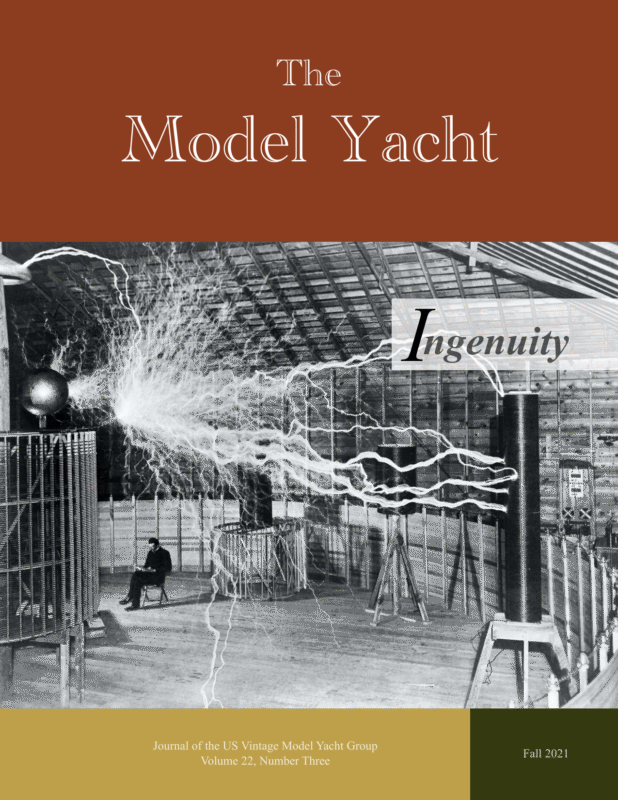
Fall 2021 The Model Yacht The Model Yacht is published three times per year by the US Vintage Model Yacht Group. Copyright 1998 to 2021 by the US VMYG. Reproduction for noncommercial purposes permitted; all other rights reserved. Other copyrights are maintained by the original holders, and such material is used here under the fair use provisions of the relevant copyright acts for nonprofit research and educational purposes. Editorial Address: John Stoudt 309 Sundance Drive Chester Springs, PA 19425 On the Cover: Nikola Tesla, the inventor of radio control as well as many other innovations relating to electricity, sits below the Tesla Coil in his Colorado Springs Laboratory. Membership Renewals: The annual membership fee will be due and should be renewed with the publication of the first journal of the calendar year. Please reference “Membership” on page 34 for dues amounts. Please use the form that accompanies this issue of The Model Yacht to complete your membership renewal. The Layline By John Stoudt Definition: A layline is a straight line (or bearing) extending from the next mark to indicate the course a boat should be able to sail on the one tack in order to pass to the windward side of the mark. (vsk.wikia.com/wiki/Layline) The National Championship Regatta is behind us (see the report on page 15, and we begin to plan for next year. If a local club is interested in hosting Nationals in 2022, please let us know. Upcoming issues of the Journal will feature design considerations, tuning and sailing, and boat identification. Increasing our membership is always a concern. We are unable to crack the membership bubble and grow beyond 250 members. Even with multiple attempts to encourage the members of the AMYA to join, our number grows slowly. So, what is the really big deal? The Model Yachting Center! The Model Yachting Center (TMYC) is an idea that a few of us have been discussing for some time now. The concept involves the development of The Model Yachting Center focusing on the preservation and perpetuation of the sport of model yachting and the development of a center that would include a museum housing various Illustration by Irwin Schuster exhibit spaces, archival and research spaces, teaching facilities for building and learning, and sailing venues as well as other things. Go to: https://usvmyg.org/the-model-yachting-centera-proposal-by-the-us-vintage-model-yacht-group/ A number of us are concerned that there is no museum devoted specifically to the historical recognition and preservation of model yachting, The people who are involved in this sport are aging, there are fewer young people becoming involved, many of the existing models and associated items are disappearing, and the potential for many more to disappear is growing every day. They will be lost to history forever. 1
Fall 2021 The Model Yacht Inside The Leadership Team…….…i The Layline……………..…..1 Barnacles………………23, 26 Before Remote Control Sailing ……………….……..4 Tesla and the First RemoteControlled Boat………..……9 Tesla’s Remote-Controlled Boat………………..…….….9 British Boat Rigging………12 US VMYG 2021 Regatta Report…………………..…15 Wind Indicator……….……22 Tech Topic: Positioning the Ballast………………..……24 Electronics Board Layout…27 And a Not So Simple Electronics Board…………28 Making a Deck Beam Pattern………………….…30 Resources…………………33 Membership Form…..……34 We are proposing the development of a facility that has one or more sailing venues; a museum with various exhibit spaces; a library and research center; archival space to house boats and apparatus, flat files, print materials, and research computers; shop space for construction and restoration activities; a classroom and “auditorium”; a boathouse: and administrative space. There are a number of unanswered questions. Is it feasible, fundable, logistically possible, and viable? Would there be enough interest? Where should it be located? What is the potential for visits and other activities? Is there enough support? And, most importantly, will it attract people? The center itself could be located on an existing body of water or scratch-built on a high point of land with a good source of water. It could be placed on donated land, private property, public land with governmental support, or an acquired piece of property. For obvious reasons a preferred location would be on fresh water rather than salt water. The building should be structurally unique, visually appealing, designed for children of all ages, and able to support varied activities. The floors could be named for the decks on a boat: Crow’s Nest, Level 4, Level 3, Main Deck, Level 1, and The Bilge. Illustration by Irwin Schuster TMYC would offer various museum exhibits, regularly scheduled regattas, kids’ activities, fundraising events, social events (weddings/ business functions), instructional classes, research endeavors, and things for adults. TMYC would support sail and power model yachts from the earliest examples to modern boats including all AMYA- and US VMYG-supported classes. The early classes that are no longer active would also be included. 2
The Model Yacht Fall 2021 Youth sailboat project – “make it and sail it”. Photo by Irwin Schuster Funding this endeavor will be the most challenging part of the project. There will need to be startup funds, one-dollar-at-atime funding, BIG contributions (sugar daddy), fundraising events, bequeathments, corporate donors, and affiliations. We need to look at large corporations, boating industry companies such as: Challenge Sail Cloth, North Sails, Boston Whaler, Hobie, Brooklin Boatyard, Hinckley Yachts, and Sparksman & Stephens. And why not take a look at the syndicates? It has been observed that banks fund some very interesting venues. We need to find individuals with experience doing this to assist with the effort. It is well known that museums struggle today. Is this a pipe dream? Sure! Maybe! But if we do not have the conversation, we will never know the possibility. Moving forward we will need to establish a board of directors, begin staged funding, establish non-profit status, and engage professionals. The board should consist of president, secretary, treasurer, dedicated individuals, and idea people all with varied experiences. The financial plan needs to include finding startup funds, hosting major funding events to achieve large goals, and then creating a regular income stream and defining alternative strategies. The effort needs to develop major areas of focus, define responsibilities, develop a marketing strategy, establish funding goals, and identify outside resources. This effort to establish The Model Yachting Center is about preserving what we love to do. The US VMYG needs your input. •What do you think of this concept? •Does it have merit? •Do you think TMYC would attract people? •Do you think it would attract regattas? •Where should it be located? •Would you like to be involved? How? •Would you contribute – boats, other artifacts, time, and money, whatever? •If you know someone who would be a good addition to the board, tell us. Let’s make it happen. If you have comments, questions or ideas please feel free to contact me at 610-316-8695 or jstoudt309@gmail.com 3
Fall 2021 The Model Yacht Before Remote Control Sailing This article was first published in Issue 197 of Model Yachting. It is being reprinted here with some additional information. All illustrations are from past issues of The Model Yacht. Article by Alan Suydam Many of you reading this article have been sailing remote-controlled model boats for years. But have you considered how the early skippers of model sailboats were able to control their boats without any electronic link between the skipper and the boat? results in the boat deviating course and requires corrections by the skipper to get back on the desired course. Vintage hull design is completely different. The basic hull shape is more like a “V” section with a shorter keel fin and a radiused garboard section to simulate the full-scale yachts of the time. A skeg was positioned in front of a small rudder blade. These attributes were designed to keep the model sailing on a straight course as determined by the skipper. Hull designs were also tested to make sure the model would stay on course if heeled by a puff. Models were usually sailed with a team of two. The skipper set the course and launched the model, and the mate waited upwind to tack the model by physically turning it with a long pole. Just like today, the skipper who was successful in getting the model to track straight, so fewer tacks are required before the finish line, does well. Before remote control, the design of the boat and rigging, a mechanical steering device connected to the rudder, and the skill of the skipper were the only ways to make the model boat go where you wanted it to. Competitions were mostly sailed on closed ponds with courses set up for individual windward and leeward legs. Points were awarded for finishing positions on each leg; the total score determined finishing positions. So, here are the details behind each of the three critical areas of Boat Design, Steering Devices and Skipper Skills: Rig design was typically sloop rigged with a small (30% total sail area) jib and larger main. Jib and main booms had jack lines with round bowsies running on the jack line to set sail trim. This allowed rapid sail trim when the model reached the shore but maintained trim under sail. Offset jib booms and main boom vangs were sometimes used to control boom lifting, particularly downwind. Spinnakers were sometimes added for downwind legs in some classes. Boat Design Modern model boat hulls tend to have shallow “canoe bodies” with long fin-and-bulb keels and spade rudders. With remote control, the emphasis is on maneuverability, especially at the start and at the marks. The skill of the skipper at the controls maintains the course and allows instant changes in course to suit the wind conditions and tactics. Relaxing your concentration when sailing usually 4
Fall 2021 The Model Yacht Steering was accomplished based on the degree of heel that the hull experienced during wind gusts. The more a boat heeled due to a wind gust, the more that the heavy rudder blade would pivot towards the lee side. The passage of water along the rudder blade tended to return the rudder to the central position when the wind slacked. On more complex systems a series of alternate rudders with different weights and sometimes different rudder shapes could be substituted to fine-tune the degree of steering correction. Rudders like the one shown below had adjustable sliding weights. A simple sheet to tiller gear. There are two sheets, one for the beat and one for the run. When the beating sheet is set, the running sheet is slack. A tensioning rubber runs from the tiller to an adjusting cleat. Image from the US VMYG archives. Mechanical Steering Devices The second most important design consideration on a model yacht without remote control is the steering device. There was a wide variety of ideas and devices to keep a straight course, particularly in a shifty wind. Spring-loaded devices were early designs, with more sophisticated vane steering being used later. Here are some of the more successful ideas. Weighted Rudder The first attempts at movable steering to keep a model boat sailing straight involved free-swinging weighted rudders. The general shape of those rudders reflected designs seen on full size boats of that period. The system involved a metal rudder that was mounted to allow it to swing freely. 5 Photo by Russell Potts
Fall 2021 The Model Yacht Tiller Gear Braine Gear The earliest method of trying to keep models sailing a straight course was just fixing the rudder on a predetermined setting. A brass tiller was attached to the rudderhead and led through a traveler with adjustment wheels. By turning the adjustment wheels, you could set the tiller to a fixed position or a limited travel to either side to suit the model. This method only worked if the wind was constant in direction and velocity. Any variance would throw the model off course. Also known as quadrant steering, the Braine gear was the next step in compensating for wind direction and velocity. It consisted of a brass quadrant mounted on top of the rudder shaft with multiple holes in the radius for a set of clips to be inserted. These clips were attached to the jib and main sheets with the sheet lines crossed so that a pull on the sheet resulted in the rudder being turned to leeward to keep the model heading straight during a puff. Typical model setups were with a slight weather helm so that the rudder could keep course when the wind puff came. The quadrant also had a centering spring or rubber band that was adjustable to compensate for the force of the wind on the sails. The skipper had to guess the wind speed on the course. Misjudgment of the wind force usually resulted in early or late arrival at the shore for the next tack. The basic layout of a Braine steered model yacht. Image from the US VMYG archives 6
Fall 2021 The Model Yacht Vane Gear The next step in reading the wind came with the vane gear. This design is still used today on full-size sailboats to act as self-steering during long ocean passages. A vane or feather is attached to a pivot behind the rudder post and is mechanically linked to the rudder. Typically, a brass strip or rod is used as a sliding arm so the vane can steer the rudder. Simple vane gears are just set to the wind which suits the model course and the model keeps a course relative to the wind vane setting. If the wind veers, so does the model. More complicated versions are mechanical marvels which can self-tack when the wind changes direction. An expert skipper with a self-tacking vane gear can get the model to the other end of the pond without the mate having to tack the boat. Free-Sailing Skipper Skills Automatic steering gear for model yachts. Image from the US VMYG archives 7 Setting a modern R/C boat’s sails to the wind conditions usually consists of luff tension, foot round, and twist and leech tension. These controls were available to the free-sailing skippers as well. Usually round bowsies controlled the luff and foot tensions and early boom vangs with
Fall 2021 The Model Yacht In Conclusion line and bowsies set up the leech and twist. However, modern skippers have the advantage of luffing the sails if the boat becomes overpowered on the course and varying the sheeting to suit the course (windward or leeward). The free-sail skipper needs to become very familiar with his or her boat’s sailing characteristics. Does the boat have a tendency to sail to windward or leeward? Does adjusting the jib or main separately have an advantage in keeping the boat straight during a puff? How does the spinnaker act and should the the main or jib be set to compensate? This article deals with the major ways model yachts were controlled before remote control came into existence. There were many other ways used to control early model yachts such as a weighted rudder. Sailing was conducted on ponds and larger bodies of water. When sailing was done on large lakes or in harbors the models were chased with skiffs. Imagine 12 model yachts on the water with their skippers chasing after them in a skiff to make the necessary adjustments to the control mechanisms. Skiff sailing. Image from the US VMYG archives 8
Fall 2021 The Model Yacht First Tesla and the Remote-Controlled Boat Article by Ken Young Born in 1856, Nikola Tesla was a Serbian-American inventor and engineer. He is best known for his contribution to the design of an alternating current electrical supply system. He was a futurist who worked with Thomas Edison for a short time and then went on his own and secured numerous US patents. Nikola Tesla’s remote control boat, patented in 1898. Photo Public Domain via the Nikola Tesla Museum, Belgrad 9 Tesla’s Remotecontrolled Boat Article by John Henderson Nikola Tesla demonstrated a radio-controlled boat in 1898 at the Electrical Exhibi9on in Madison Square Garden. His inven9on is described in US patent #613,908, which is dated November 8, 1898. The key concept of control at a distance, without any wires or other mechanical connec9ons between the controller and the controlled boat, was almost magic in its day. Radio itself was new at the 9me. Tesla had filed a patent applica9on for basic radio just one year before this demonstra9on in September 1897, but the patent was not granted un9l March 1900. There was a fascina9ng and disturbing baQle with Marconi over the basic radio patent. Marconi’s patent applica9on in the US in 1900 was denied at first because of Tesla’s prior work. Inexplicably, the US Patent Office reversed itself in 1904 and granted Marconi the radio patent. But in 1943 the US Supreme Court upheld Tesla’s radio patent. Explana9ons for all this are murky, involving both poli9cs and financial clout.
Fall 2021 The Model Yacht Most important to the R/C world was his design and propulsion. His patent description was, “Method of an Apparatus for Controlling Mechanism of Moving Vehicle or Vehicles.” In 1898, at Madison Square Garden, Tesla set up an indoor pool. He had a 4-ft long miniature ship and a control box with several levers. The Nikola Tesla (1856–1943) deck of the ship Scientist and Inventor. had three antennas. The tallest was in the middle, and the outside two had lights on top to indicate position and direction at night. Inside there was an electric motor that drove both the propeller and rudder, a storage battery, and a device for receiving radio waves sent from the control box. He called his invention a “Teleautomoton”. This particular demonstration craft was dubbed Devil Automata. His patent description was, “Method of an Apparatus for Controlling Mechanism of Moving Vehicle or Vehicles.” We have to remember that at that time few people knew that radio waves even existed. Tesla was an inventor to make money and was a showman who promoted his creations in sometimes flamboyant fashion. At the beginning of the demonstration he informed the crowd that it worked by magic. He would yell at it to make it do what he 10 Tesla’s boat was about 4 Z long, built of steel, and described as “tub-like.” He was demonstra9ng control, not naval architecture. The transmiQer had a “Tesla oscillator” that emiQed radio frequency pulses through a tuned circuit and antenna; the receiver had a matching tuned circuit to recover these pulses. The tuned circuits are important to improve the sensi9vity of the receiver and to eliminate interference from other sta9c generated (for example) by the electric motor in the boat. Tesla men9ons specifically the care needed to prevent and filter out sparking from the relay contacts that controlled the motor. Tesla invented a kind of radio-ac9vated switch that he called a “coherer”, which would become conduc9ve aZer receiving a pulse. The switch mechanism is interes9ng. It was a container with small and carefully manufactured metal oxide par9cles. The pulse caused the par9cles to align (electrosta9cally?), make contact with each other, and form a conductor.
Fall 2021 The Model Yacht Nikola Tesla’s remote control boat, patented in 1898. wanted, leading some observers to speculate that there was a trained monkey inside. He demonstrated that it could answer questions from the crowd. Someone called out for the cubed root of 64. The lights on the antennas flashed four times. Of course, Tesla was moving levers on the control box. He then showed what was actually happening with the control box. Since there was no visible connection between the control box and the boat, he said the boat had a “borrowed mind” that responded to orders from a distant and intelligent operator. He saw great potential for military use. He eventually developed unmanned torpedo boats carrying an explosive charge directed by radio waves, much like modern day drones. It wasn’t until the late 20th century that the military made significant use of his invention. The accompanying article by John Henderson explains more about the technical aspect of his invention. Bibliography ARS Technica July 17, 2013 Engadget J Turi January 19, 2014 Insider “We Are Mighty” Logan Nye August 25, 2016 Tesla Memorial Society 11 The current from the switch rotated a disk through discrete posi9ons through a clockwork escapement mechanism. Each posi9on had a set of contacts that ac9vated specific func9ons: turn rudder right; turn rudder leZ; stop turning rudder; run the electric motor; turn the motor off. The operator had to step through these func9on op9ons sequen9ally, but apparently could do so rapidly. There were lights on top of the boat to tell the operator the posi9on of the disk. AZer the disk rotated to its next posi9on, a geared mechanism would flip over the container of the par9cles so that the next signal could be received. Sources 1.PBS.org. “Tesla – Inside the Lab – Remote Control” hQp://www.pbs.org/tesla/ ins/lab_remotec.html. 2.Tesla’s US Patent #613809A, issued 1898 “Method of and apparatus for controlling mechanism of moving vessels or vehicles.” hQps:// patents.google.com/ patent/US613809A/en. 3.Tesla Memorial Society of New York. hQps:// www.teslasociety.com/ radio.htm. 4.Inven9on of radio – Tesla vs. Marconi.” hQps:// www.pbs.org/tesla/ll/ ll_whoradio.html.
Fall 2021 The Model Yacht BRITISH BOAT RIGGING Article and photos by John Stoudt A number of years ago I acquired a British Marblehead from Rob Weeks. Rob’s father was an American businessman in London and bought the boat (Pirate) for Rob in the mid 1970s. It was sailed on Round Pond in Hyde Park. They lived nearby. The way the boat was made, Rob could pick the boat hull by a handle (attached to the deck), grab the bag of sails and the spars, and head off to the pond. How the boat and rigging were built for any type of air from light to heavy with interchangeable parts and adjustment points was ingenious. After conversations with Graham Reeves of the UK we think this boat was built by Chris Dicks in the early 1970s. There is a photograph in Graham’s book, 100 Years of Model Yachting & The Model Yachting Association, on page 42, of Chris’ boat Revolution. It looks very much like Pirate. Loose parts were laying in the hull. She must have taken on water while sailing because there was a drain hole in the transom. This was due to the slotted mast opening in the deck. This free-sailed boat was in rough shape. All of the glue joints had failed, the deck was off of the boat and many of the fittings had been removed and were in the hull. The boat has been fully restored with all of the glue joints cleaned up and epoxied, electronics installed, a new deck applied, and an entirely new rig. And it sails pretty well! As stated above, the ingenious part of this boat was the original rigging. The entire rig could be set up and adjusted for various winds. The boats had three sets of sails rolled and slid into pockets in a plastic store bag labeled LASKYS. Showing the glue failure, true of all joints in the boat. Transom showing the hole for a drain plug. 12
Fall 2021 The Model Yacht • A number of the fittings were custom made out of Bakelite, including: the jib club attachment, the mast collars, and the gooseneck components. Jib boom assembly with club footed attachment, sliding channel and jib boom in place. Stitched sail bag (plastic store bag) with three suits of sails stored for transport. • The sheet adjustment points were on a sliding arrangement. LASKYS was an electronics chain in the UK around the time this boat was acquired. Some other interesting items about Pirate: • The shroud racks had multiple adjustment holes. • The mast was keel-stepped, sliding through an elongated hole in the deck. This was so the mast could be moved forward and aft to accommodate changes in the wind speed. Sheet adjustment track. Let us focus on these very ingenious features of the rigging on this boat. 1. There were three sets of sails, an A suit, a B suit, and a C suit. These were kept rolled up in the bag described above for storage and transport to the pond. Not highly recommended but in this case an effective way to carry them about. Open mast slot in the deck. • The jib was club-footed and fit into a plastic channel so it could be moved (with effort) fore and aft depending on the wind and whether the boat was running or jibing. 13
Fall 2021 The Model Yacht 2. The spars were made out of ½-in round aluminum tubing with internal sleeves in one side of all joining pieces. There were four mast pieces that could be assembled to accommodate light, medium, and heavy air and thus the A, B, and C sails. The main and jib booms each had four pieces: a base piece and three extensions labeled Jib A, Jib B, and Jib C and Main A, Main B, and Main C. These could be quickly assembled based on wind speed. Hooks used to attach the sails to the mast and booms 4. The jack lines were fastened to the mast using vinyl tape. Jib and main boom extensions for light, medium, and heavy air Mast components showing tape used to hold jack lines to the mast 3. The sails themselves each had hooks on them at each corner that could easily be hooked to the attachment points on the mast and booms. The overall impression looking at the rig components is “clunky”, but it was obviously effective because by all reports this boat was fast. Restored Pirate sailed in Nationals by Chuck Lage, a CSMYC member. Photo by Judy Bonanno 14
Fall 2021 The Model Yacht US Vintage Model Yacht Group 2021 Regatta Report Marbleheads Running the Windward End of the Course. Photo Judy Bonanno Article by John Stoudt T he Chester Springs Model Yacht Club (CSMYC) hosted the 2021 US Vintage Model Yacht Group National Championship Regatta on October 6–10, 2021 at Tel Hai Camp and Retreat Center in Honey Brook, PA. Club volunteers welcomed over 30 skippers and over 60 vintage model yachts to this five-day event. Skipjacks, Schooners, Unrestricted boats (those that do not fit in other US VMYG classes), Vintage 36s, and three groups of Marbleheads raced during the regatta. The skippers arrived from 10 states, including Delaware, Florida, Illinois, Maryland, Massachusetts, New Hampshire, New Jersey, New York, Pennsylvania, and Virginia. The regatta committee was made up of CSMYC members and others, including Dick Bardsley, Martin Blumenthal, Ronnie Brandt-Simpkins, Judy Bonanno, Dave Branning (AMYA, Region 2 Director), Melinda Bugg, Jim Freeze, Tim Good, George Hotton, John Kathman, Chuck Lage, Beth Lippincott, David Martin, Richard McOrmond, Nick Mortgu, John Stoudt, Scott Todd, and Tom Werner. The regatta results listed by class include the design of the boat. We are builders and sailors of vintage model yachts and respect the origins of each boat. We also like to sail fast vintage models. So, knowing the origins of each boat sailed helps us do that. 15
Fall 2021 The Model Yacht Skipjack 48 Weather: West, 0–2 mph; mostly cloudy Skipjacks Making to Windward. Photo by Judy Bonanno Place Skipper Sail # Design Points 1 Stanton Smith 7 Pepper Langley 10 2 Ken Young 83 Pepper Langley 14 3 Rob Dutton 53 Pepper Langley 23 4 Colin Parker 49 Pepper Langley 24 5 Wayne Winokur 34 Pepper Langley 40 6 George Hotton 60 Pepper Langley 44 7 Domenick Bonanno 22 Pepper Langley 45 8 John Stoudt 97 (Boat Trouble) 46 9 Richard Bardsley 58 (Boat Trouble) 50 Scott Todd 25 Did not attend Schooners (50 in and under) Weather: West, 0- 3 mph; mostly cloudy Schooners and Unrestricted Boats Rounding the Windward Marks. Photo by Judy Bonanno 16 Place Skipper Sail # Design Points 1 Tim Good 204 Terrapin Sharpie 36 2 Tom Alessi 777 Sharpie 38 3 Ken Young 83 Sharpie 47 4 Rob Dutton 53 Sharpie 55 5 Clif Martin 12 NC Oyster 60 Sharpie Jim Linville 12 Did not compete
Fall 2021 The Model Yacht Schooners (over 50 in) Weather: West, 0- 3 mph; mostly cloudy Place Skipper Sail # Design Points 1 John Stoudt 309 Valmore 7 2 Domenick Bonanno 79 Gary Webb 38 Unrestricted Boats These boats are all different sizes and classes and do not fit into one of our other classes; therefore, they are sailing as unrestricted boats Place Skipper Sail # Design Points 1 Mike Denest 144 Int A Boat 16 2 Martin Besant 40 Gaff Rigged Cutter 18 3 Robert Rotolo 50 Boucher Seagull 32 John Henderson 45 Did not attend Alain Jousse 49 Did not attend 17
Fall 2021 The Model Yacht Place Skipper Sail # Design Points 1 Herb Dreher 42 Comet 29 2 Ivor Walton 340 Chico II 56 3 Jeff Gros 60 Scampi IV 58 4 Cliff Martin 34 Comet 59 5 John Stoudt 97 McLaughlin Sharpie 70 6 Tom Werner 5 Suydam Sharpie 80 7 Ken Young 183 Magic Dragon 94 8 Rob Dutton 53 Chico II 103 9 Stanton Smith 933 Original Design 126 10 John Henderson 45 April Bunny 137 11 Colin Parker 249 Chico II 140 12 Domenick Bonanno 79 Petersen 166 TB 13 Rick Gates 1 Petersen 166 TB 14 Bill Sysyn 333 Chico II 172 15 Martin Blumenthal 49 Chico II 197 16 Wayne Winokur 33 Original Design 204 17 Rick Laird 39 Starlet 245 18 Jeff Beck 56 Darling 20-rater 251 19 Jim Linville 51 Rip Tide 278 Vintage 36/600 Weather: Wind East, 0-3 mph; mostly cloudy and East, 8–12; partly cloudy V36s in Light Air. Photo by Chuck Lage 18
Fall 2021 The Model Yacht Place Traditional Vintage Marblehead 50/800 Weather: Wind 8–12 mph; partly cloudy & Wind 8–12 mph; rain Skipper Sail # Design 1 Ivor Walton 240 Madcap 50 2 Domenick Bonanno 79 Madcap 56 3 John Henderson 140 Mad Hatter 58 4 Rick Laird 32 Madcap 59 5 Colin Parker 149 Norumbega 90 6 Rob Dutton 67 Peony 92 7 John Stoudt 97 Tritonia (boat trbl) 8 Stanton Smith 142 Mad Hatter 96 9 Melinda Bugg 86 Cheerio 100 10 Tom Alessi 777 Madcap 126 11 Rick Gates 122 Unknown 130 12 Chuck Lage 150 British (Dunklin) 133 13 Bill Sysyn 1033 Madcap 139.5 14 George Hotton 84 Madcap 161 15 Jeff Beck 818 Norumbega 162 16 Jim Freeze 108 Sunkiss 168 17 Jim Linville 151 Madcap (boat trbl) 214 18 Wayne Winokur 133 Boucher #1 223 Richard Bardsley Boat Trouble Alain Jousse Did not attend Steve LaBrenz Did not attend High Flyer Vintage Marblehead 50/800 Sail # Design 1 Cliff Martin 2 Herb Drehen 96 Sunwind Scott Todd 197 Did not compete 1040 Magic Dragon I Points 17 26 19 93.5 Classic Vintage Marblehead 50/800 Weather: Wind 8–12 mph; Weather: Wind 8–12 mph; partly cloudy & Wind 8–12 mph; rain Place Skipper Points partly cloudy & Wind Place Skipper Sail # Design Points 1 Ken Young 283 Bingo 33 2 Jeff Gros 1938 Delta 43
Fall 2021 The Model Yacht Rob Dutton, the US VMYG Awards Coordinator was on hand to present all of the race awards and place chevrons as well as a few special awards which included: This event also included a symposium, “By the Water”, on Friday, October 8, 2021. There were the following presentations and a parade of boats. 9:00 am – Making a Scaled (Down or Up) Model that Sails Well John Henderson (Chestertown, MD) 10:00 am – Making a Mold of and Casting a Lead Ballast Scott Todd (Woolford, MD) 11:00 am – Milestones in Model Yachting Cliff Martin, Medway, MA 12:00 noon – Lunch and Parade of Boats (lakeside) 2:30 pm – The Model Yachting Center – A Discussion John Stoudt (Chester Springs, PA) 3:30 pm – Early Catamaran Models TJ Perrotti (Newport, RI) The Earl Boebert Craftsmanship Awards • Skipjack – Stanton Smith, Annapolis, MD • Unrestricted Class (Gaff Rigged Cutter) – Martin Besant, Piscataway, NJ • Vintage 36 – Stanton Smith, Annapolis, MD • Marblehead – Stanton Smith, Annapolis, MD The Marshall Croft Sportsmanship Award • John Henderson, Chestertown, MD The Parade of Boats Awards • Tallest Boat (Int A Boat)– Mike Denest, Newark, DE • Shortest Boat (Darling 20-rater) – Jeff Beck, Germantown, MD • Most Intricate, Most Sails, Largest (Yawl Iris) – John Stoudt, Chester Springs, PA • Most Unique (Proa or Malay Jong) – John Stoudt, Chester Springs, PA • People’s Choice (Rainbow) – John Henderson, Chestertown, MD • Oldest (Starlet) – Rick Laird – Charlestown, MA Roughly 40 individuals attended the program and thoroughly enjoyed the presentations by some very recognizable individuals in model yachting and naval architecture. Candace Stoudt did a piece of mixed media art that was reproduced into a poster for all regatta participants. Club members were eligible for the drawing for this piece of art because it depicted work the club was involved in in 2021. It went to a club member Joe Paradine. In a gift bag provided by the Chester County Convention and Visitors Bureau the skippers found their regatta shirt which was emboldened with old model yacht sailors. The spouses were taken on two day trips to Terrains Garden Center and Longwood Gardens. “Old model yacht sailors” Tee Shirt. Photo Judy Bonanno 20
Fall 2021 The Model Yacht The US VMYG has been expanding the boats supported by the group and has increased numbers at regattas with the addition of the Unrestricted Boats class and the Classic Marbleheads. There were a few boats sailing from England and one from Italy. Mad Hatter (a Roger Stollery design) and Pirate (a Peter Dunkling design) were the British boats participating. The Italian (a Brusotti design) boat came to the US in 1955 and was finished here. Mad Hatter was redesigned into V36 version, April Bunny, by John Henderson, and two of these were in the regatta. There were multiple Classic Marbleheads in the event. John Stoudt offered his boats to club members, “they are not doing any good sitting in the house”; so, eight of his boats sailed in the regatta. We had Mike Denest’s International A boat sailing, a boat that has not been on the water for years. Jeff Beck sailed a Thomas Darling 20-rater in the V36 class. There were two Boucher (early purveyor of model yachts in New York City) boats sailing: a Boucher #1 built by Stanton Smith and sailed by Wayne Winokur and a Boucher Seagull built and sailed by Robert Rotello. John Stoudt’s Valmore, built by Alan Suydam, is quite a boat to see on the water and is very fast. The V36 Sharpies did well. Happy Regatta Participants at the Picnic. Photo by Judy Bonanno A Thom McLaughlin adaptation of the Star Sharpie, started by Alan Suydam and completed by John Stoudt did very well for its first competition. One of Alan Suydam’s modified Star Sharpies also performed well on the water. Martin Besent was sailing a beautiful gaff-rigged cutter he built using an EC-12 hull he had laying around. CSMYC sails on the lake at Tel Hai Camp and Retreat Center. The camp is very supportive of our club and in allowing us to sail on their lake. They also provided a lot of logistical support for the regatta and prepared a wonderful picnic at the lake on Friday evening after a full day of racing. Kudos to them! Here is the link to the photos taken at the regatta: https:// judybonanno.smugmug.com/Sailing/Vintage-Regattas/ USVMYG-2021-Natl-Regatta Chuck Lage prepared a number of composite videos of the regatta that can be found They can be found here: https://www.youtube.com/ results?search_query=US+Vintage+Model+Yacht+Group. Enjoy! Special thanks to Judy Bonanno, Chuck Lage, Rick Gates, and Richard McOrmond for their photographs and videos. 21
Fall 2021 The Model Yacht Wind Indicator We have tried all types of wind indicators from very fancy to quite simple. The design for this one came from Ken Shaw, a member living in Rock Hall, MD. It works pretty darn well and is simple to make. The sleeve spins freely on the music wire powered by the wind on the ribbon. Article, photo, and illustration by the TMY Editorial Staff Materials needed: • 4-in length of 0.022-in music wire • One crimp (#3) or small diameter tubing, cut to length • Clear duct tape – cut to fit • ¼-in silver Mylar® ribbon, 6 in length Tools needed: • Wire cutter • Needle nose pliers • Another pair of pliers • X-ACTO® knife Procedure: 1. Cut a 4-in piece of music wire. Be sure to clean off the wire with a good solvent as it is usually very oily. 2. Make a 45-deg bend 1 in from the end of the wire using both pairs of pliers. 3. Make a second 45-deg bend ¼ in from the first bend so the short end is parallel with the long end of the wire. The bends need to be in a single plane. 4. Slide the crimp over the short end. 5. Make the last bend at a 45-deg angle above the crimp (see the drawing). 6. Make sure that the bends lay flat on your workbench. If they do not, adjust them so they are in the same plane. 7. Cut a piece of silver Mylar 6 in long or whatever length you like. 8. Attach the Mylar ribbon to the sleeve using duct tape. Make sure that the tape is adhered to both sides of the mylar and wraps around the sleeve. 9. Next drill a #63 hole, vertically in the top of your mast about ¾ in deep. You may need to drill through the mast crane. 22
Fall 2021 The Model Yacht NOTES: 1. You can make the wire and Mylar ribbon any length you want. Longer lengths may get caught in the rigging of your boat. 2. The Mylar ribbon can be any color; however, silver reflects light well and is easy to see against most backgrounds. Other colors do not reflect the light as well and are hard to see in flat light. 3. The width of the ribbon and the number of strips of ribbon can vary depending on what you like and what you can find. We found the cheerleading pom-poms are a nice source of Mylar. They can be found in party stores. 4. If you increase the number of ribbons you use or the width you can simply increase the number of sleeves you use and change the length of the area where the sleeves are to accommodate more. Make sure you leave enough room for the sleeves to rotate freely. The little squiggly bends at the ends of the wind indicators (see photo) act as ‘hold fasts” and keep the wind indicator in the hole in the top of the mast. The one with the additional bends on the bottom fits into a hollow (aluminum) mast. When you start the process, you will want to make a handful of these. Good luck and have fun! Barnacle VMYG—Our sister organization the Vintage Model Yacht Group (United Kingdom) offers membership in the organization for £20 per year. They produce two publications, The Turning Pole and The Pond Side. Both are enjoyable to read. If you are interested, you can join by sending a check to Geoffrey Turner, payable to Vintage Model Yacht Group and send it to: Geoffrey Turner, 17, Wilburton Road, Haddenham, Ely. Cambs. CB6 3SX Or pay by PayPal if that is easier. Go here http://www.vmyg.org.uk/aboutus.htm and send an email to the secretary. 23
Fall 2021 The Model Yacht Tech Topics: Positioning the Ballast Article, photo, and illustrations by John Henderson exactly, the amount and position of the ballast is probably indicated reliably. But what if we are scaling the plans to a different size—perhaps by building a scale model of an existing full-size boat or by transforming a favorite design to a larger or smaller class (e.g., a Vintage Marblehead to a Vintage 36, or vice versa)? Maybe we want to change the keel to make it deeper (as the AMYA J-Class does), have a more vertical leading edge, or have a different profile in the trailing edge. Maybe we want to move the rudder or make it An alternative to the mildly If the boat is to float level, this ballast bigger. Any of these analytical techniques changes has the must be in the right place, and the described in this note—and a potential to require reposition can be found simply, without common practice in modeling examination of the —is to float the hull in a pool location of the ballast. arithmetic computations. and adjust the ballast in both Additionally, and especially in full-keel models, the deepest part of amount and location until the boat floats level on the keel may not be where the ballast must be its waterline. (Of course, you need a pool that is placed. The starting point is the location of the big enough and deep enough, and I have found that Longitudinal Center of Buoyancy of the hull. a bathtub rarely works.) But waiting until the hull This is (almost) always shown on the plans as is finished before determining exactly where and either “LCB” or perhaps just “CB”. This is, how big its major weight component is risks basically, the center of the underwater volume of surprises and makes it less likely that the hull the hull. (If necessary, the LCB can be calculated structure will be optimum. We can and should plan as a simple extension of the calculation of the ballast much earlier in the build process. displacement; these two computations may be the Planning also minimizes the need for “trim” ballast, subject of a future “Tech Topic”.) inserted at the last minute to “correct” a problem that was avoidable. Trim ballast adds weight and The LCB can be thought of as the fore-and-aft increases the pitching moment, because the trim place where the flotation forces are concentrated. ballast is likely located in the ends of the boat. In a sense, it is analogous to the more familiar concept of Center of Gravity. If building from plans and following them The heaviest single component, by far, in our models is the ballast. Typically, the ballast is at least 60% of the total weight, unless forbidden by class rules (e.g., the Skipjack 48). If the boat is to float level, this ballast must be in the right place, and the position can be found simply, without arithmetic computations. As will be explained, the ballast position can be determined early in the building process, when it can be planned into the structure, and it can be accomplished even before the hull is waterproofed and floated. 24
The Model Yacht If the boat is to float level, its Longitudinal Center of Gravity (LCG) must be at the same fore-aft location as the LCB. I think this is intuitive, but a few explanatory words: The weight of the boat is pulling downwards, and the location of this force is at the LCG. The buoyancy of the boat is pushing upwards, and the location of this force is at the LCB. If the LCG is aft of the LCB, the boat will be down at the stern; an LCG forward of the LCB puts the bow down. See Fig. 1, where the ballast is located within the dashed lines deep in the keel. The first sketch shows the ballast located correctly to put the LCG below the LCB, and so the designed waterline (DWL) is level. The second sketch shows a ballast location that puts the LCG aft of the LCB; the designed waterline (DWL) is no longer level, and the boat floats bow-high. Note that this incorrect ballast location, for a hull profile shape such as the one drawn in the figure, actually puts the ballast lower. Lower ballast might be tempting for stability, but stability cannot be achieved at the expense of floating level. Since we know the location of the LCB from the design drawings, and we know that the LCG must be located at the same fore-aft position, we can use this knowledge to locate the ballast by balancing the boat “in the air”. Without ever floating the boat – in fact, well before it is even waterproofed – we can suspend the hull in the air at the LCB point. We can then add weight equal to the planned ballast weight to the hull and move the weight around until the boat hangs level. It is not necessary that the ballast fit perfectly down into the lower reaches of the hull at this time, we are only determining the fore-and-aft position. Fig. 1. The relationship between the Longitudinal Center of Gravity (LCG) and the Longitudinal Center of Buoyancy (LCB). 25
Fall 2021 The Model Yacht The photo shows a convenient method of suspending the hull. Note that the main hatch is almost always located approximately over the LCG and LCB because it is typically the widest and deepest part of the hull. I normally make my hatch frame strong enough to support the full weight of the boat so that I can use it as a carrying handle. For the photo, I inserted a temporary wooden bar fore-and-aft in the center of the hatch; a loop of string placed so that the boat hangs level reveals the LCG, which must match the LCB. An alternative is to insert a dowel across the hatch opening at the LCB (determined from the plans). Suspend the boat by this dowel. When the ballast is located properly, the boat will hang level. I acknowledge that this method only determines the balance of the hull and ballast. We have not yet explicitly included the radio and rig. But the ballast is dominant, and the rest of the hull is likely the second-most weighty component, so we are very close. I would argue that the rig can be compensated by adjustment of the positions of the radio components, but the more fastidious among us could add small weights at the expected locations of the mast and radio to fine-tune the balance. Float on your waterline. Barnacle Boat without its ballast – Have you ever seen or found in an antique shop a vintage model yacht without its ballast? The boat was probably built before World War II. During the war there was a lead shortage. Many boats lost their ballast in the war effort. 26
Fall 2021 The Model Yacht Electronics Board Layout Article by John Stoudt There are many options for building an electronics board and many designs available. This layout is simple, practical, and greatly reduces the chance for a sheet to get caught on items mounted on the electronics board. The sail arm placement and movement do not interfere with the rudder arm and movement. An alternate location for the receiver would be to mount it above the rudder servo on the back inside edge of the hatch opening with hook and loop material. The leads can be bundled right in front of the rudder servo and brought up and plugged into the receiver. The arm can swing freely and not interfere with the leads. Switches seem to be the most problematic items on the electronics board. More and more individuals are excluding them and plugging directly into the receiver. The screw eyes used to tie off the sheets below deck should be forward (jib) and aft (main) of the swing arm at end of full out travel to ensure no reserve travel of the sheet/s at the end of the sail arm travel. If the corners of the electronics board could catch the sheets they can be rounded. NOTE: All items are centered therefore balancing the weight in the boat. 27
Fall 2021 The Model Yacht And a Not So Simple Electronics Board Article and photos by Gudmund Thompson T oday was the first time that the sail control system for the Colin Archer was completely assembled. Up until now, it has really only existed in my mind. It is quite a rat’s nest of lines, but I am fairly confident that it will work to control the mizzen and main sails (which require differing sheet throws) and both a port and starboard sheet for each of the jib and the jib foresail. These sails need different sheet throws as well, and this difference is facilitated by the central trim servo. The throws are mizzen 15 cm (5.91 in), main 35 cm (13.78 in), jib 30 cm (11.81 in), and foresail 40 cm (15.75 in). The little tensioners look wonky, but they seem to do a good job of keeping the slack end of each closed loop under a little tension. Sail control system. 28
Fall 2021 The Model Yacht Board installed in the boat. The loops are all tight when the servos are at either end of their runs because the lines on the drum are stacked up, but at the center of their runs there is only a single layer of line on each drum. The really good news is that this whole setup will fit through the hatch into the Colin Archer, no disassembly required. NOTE: While it is not certain that the sail management system for the Colin Archer will stand the test of time, this summer’s outings seem to show that it works just fine. Colin Archer under sail. 29
Fall 2021 The Model Yacht Making a Deck Beam Pattern One pattern can be used for all of the deck beams on a given boat. By making the pattern correctly, the curvature on the deck will remain uniform and be reduced accurately as the beams become smaller thus maintaining the correct curve for the entire length of the boat. Article by TMY Editorial Staff Materials: • Piece of cardboard (the back of a tablet) • Pencil • Fairing stick • Scissors • X-ACTO® knife • Straight edge This method of developing a pattern for the deck beams on your boat should work for most boats. A deck should have a crown (camber) ranging from 1/8 in to ¼ in at the widest part of the hull to allow water to run off the deck. Most decks curve from bow to stern and from port to starboard. Generally, the fore to aft curve is upward at the ends and the port to starboard curve is downward at the edges. Check your plan and see if there are two lines from stem to stern on the boat’s profile. One is the sheer line (edge of deck), and the other is the top of the deck at the center of the boat. Some plans have these two lines, and others have only the sheer line. If your plan has the two lines measure the vertical difference between the two lines at the widest point of the boat. This will become “X” in the discussion below. If you do not have the two lines on your plan, then you will have to determine that dimension (X). If you look closely at the plan below, you can see these two lines. 30
Fall 2021 The Model Yacht Note that, at least in this design, both the sheer line and the deck centerline are higher at the ends of the boat than in the midships sections. This means that a deck made of sheet material (such as plywood) must curve simultaneously in two directions – i.e., we are forcing it into a compound curve. Sheet material resists this. (Try bending a sheet of paper simultaneously up fore-and-aft at the ends and down at the sides.) Over some limited bending range, you can “torture” plywood into shape. Beyond this range, it is likely to form some kind of non-fair inflection. Before making a full set of deck beams, it might be worthwhile to experiment with the candidate deck beam camber. You may find that raising or lowering the deck centerline may allow the plywood to assume shape more easily. For example, a deck with camber adjusted so that the deck centerline forms a straight line from the top of the stem to the top of the transom will not require compound bending. This process will ensure that all of the deck beams have the same proportions of this curve (camber) from bow to stern. 1. Draw a rectangle that is as long as the longest deck beam on your boat (measure to the outside edge of the hull at the deck beam location) and with a height of ¾ in plus the height you would like the center of the deck (let us call it “X”) to be above the outside edge of the deck. Place a vertical center line through the rectangle. 3. Use a fairing stick to draw an arc from the upper left mark through the top center to the upper right mark. Draw an identical arc from the lower left corner through the mark on the center line and to the lower right-hand corner. 4. Mark an area, dead center at the top of the pattern, ⅛ by 1 in, for the king plank notch. 5. Measure the length of the longest beam (on the plan) from the inside edge of the sheer clamp on the port to the inside edge of the sheer clamp on the starboard side. Split this dimension in half. Measure out that amount from the centerline of the template and draw a vertical line on each side that intersects the upper mark at each edge of the template. 6. Cut this out using scissors and an X-ACTO knife. You now have the template for the longest deck beam. It will be used for laying out all of your deck beams. DO NOT CUT THIS TEMPLATE DOWN! 2. Mark down “X” at each edge and up “X” on the centerline. “X” is either the dimension you pulled off of the plan or the dimension you chose. 7. Now trace the template onto the piece of wood you will be using for your deck beams. 31
Fall 2021 The Model Yacht 8. Using the same template, trace the next beam on the wood – mark the center line. Measure the beam length from the inside of the sheer clamp on one side of the boat to the inside of the sheer clamp on the other side. Divide this in half and measure out that amount on each side for the new beam and place vertical lines at those locations. Example used in this article with a small, fine top notch. 9. Redraw the notches at the ends of the beam. 10. Repeat the process until all of the deck beams are cut to size. Cut the beams out and check each for fit as you proceed. Example with a slight bevel where it butts against the sheer clamp. There are different ways to prepare the ends of the deck beams (see the examples) and fit them into place at the intersection of the beam and the sheer clamp. Only one method has been described here. Whichever method you chose, you will need to fair them in along the top edges of the beams, king plank, sheer clamp, and sheer strake using a flexible sanding board. This ensures that the deck touches all of these surfaces when you glue it in place. This sanding board can be made from a 4by 15-in (approximate) piece of 1/16-in plywood with adhesive-backed sandpaper (120 grit) adhered to it. This sanding board will flex very easily and can be used to sand down the high spots on the deck beams, king plank, sheer strake, and sheer clamp. You can actually see the areas abrade as you sand them by flexing the sanding aboard while you move along the top edges. If you are having trouble detecting the areas that are being abraded, take a pencil and mark all of the top edges. As you sand the pencil markings will be removed. Sand until they are all gone. The goal here is to get all of these surfaces to blend into one continuous curved surface. Example with a profile that fits around the sheer strake. A more difficult fit. NOTES: • The deck crown height is dependent on the length of a boat. A 36-in boat should have a crown of ~⅛ in while a 50-in boat should have a crown of ~¼ in. The appearance can necessitate making the crown higher or lower depending on how the resultant curve looks. Of course, larger boats would need more of a crown. Increasing these numbers will increase the potential of a non-fair deck surface. • A fairing stick is used to “fair in” curves in the boat building process. For model yachts, a 3/16- by 3/16-in piece of straight grained hardwood makes a very nice fairing stick. Make them about 6 ft long. 32
Fall 2021 The Model Yacht Resources Plans can be found from multiple sources including: • AJ Fisher – http://www.ajfisher.com/ • Pinterest – http://www.pinterest.com/pin/506866133039763052/ • Solomons Island Model Boat Club – https://sites.google.com/site/simbclub/home • Sublime Boatworks – http://www.sublimeboatworks.com • The Vintage Model Yacht Group, UK – http://www.vmyg.org.uk • US Vintage Model Yacht Group – http://www.usvmyg.org Hulls can be acquired from sources such as: • Biff Martin, Marblehead, MA – Biff Martin (978-828-9765) • Blue Crab Model Yacht, Cambridge Maryland – Scott Todd (410-310-2453) • The Vintage Model Yacht Group, UK – http://www.vmyg.org.uk Parts are available from a number of suppliers including: • Carr Sails – http://www.carrsails.com/ • Long Beach RC, Hickory Corners, MI – http://www.longbeachrc.com • Micro Fasteners – https://www.microfasteners.com/ • MidWest Model Yachts, Plainfield, IN – http://www.midwestmodelyachting.com/ • Model Yacht Fittings, The Villages, FL – http://www.modelyachtfittings.com • Pekabe (Worth Marine) – https://www.ebay.com/b/pekabe/bn_7024907023 • SAILSetc (UK) – www.sailsetc2.com • ServoCity – https://www.servocity.com/ • Tower Hobbies – https://www.towerhobbies.com/ 34
Fall 2021 The Model Yacht Membership Form NAME ___________________________________________________ AMYA # ______________* First Initial Last STREET _____________________________________ PHONE # ___________________________ CITY ____________________________ STATE ___________ CTRY __________ZIP _________ Email Address ____________________________________________________________________ (required) *The US VMYG recommends membership in the AMYA. DUES – emailed newsletter (new members) $30.00 for U.S., Canada, and Overseas DUES – mailed newsletter (we ask current members to help reduce costs – select emailed newsletter) $40.00 for U.S. and Canada $50.00 for Overseas Life Member Contribution in the amount of $ _______________ COMPLIMENTARY MEMBERSHIP – The US VMYG makes complimentary memberships available to museum personnel, school directors, et cetera by email only. If you would like to have a complimentary membership for your organization, please provide an email address for the individual who will be receiving the newsletter and other communication. Organization: _____________________________________________________________________ PREFERRED METHOD OF PAYMENT: You may now join/renew electronically at: https://form.jotform.com/90405575663966/ Mail in membership: You may also send a check along with this form for the correct amount to: US Vintage Model Yacht Group 1 Rampart East Media, PA 19063 NOTE: The US VMYG will not share your personal information with outside parties. 34 November 2021


