Construction of a Plank on Sawn Frame Marblehead Class Model Racing Yacht to Ted Houk’s 1949 Rip Tide Design
by Earl Boebert
An American tenor was singing for the first time at La Scala, nervous at being in front of the toughest and most knowledgeable audience in the world. He sang his first aria and the audience leapt to its feet and shouted “Encore, Encore!” So he sang it again. Again the cries of “Encore, Encore!” He leaned down and whispered to the conductor “How many times am I going to have to sing this?” “Until you get it right,” whispered the conductor back.
The Design
When the Vintage Group was just getting started, I began and completed a series of half-models to display at various events we might attend as a way of attracting potential members. The half-models gave the history of the Marblehead or “M” class of model racing yachts from its inception in the early 1930s to 1949. The M class was, and still is, a development class with minimum constraints on design and construction. The basic rules are that the boat must be 50 in long overall and carry no more than 800 in2 of sail.
The last hull I carved was that of Rip Tide, a 1949 design by the late Ted Houk of Seattle. It took me three tries to get it (almost) right; this, although I didn’t know it, was an omen. The hull form is very sophisticated, starting with a “hollow” or “clipper” entry, transitioning to a broad stable midsection and carrying off to flat floors aft to encourage planing.
A naval architect looked at the half hull at the 1996 WoodenBoat Show and had to be reassured a couple of times that she was a 1949 design; his comment was that “The 12 Meters didn’t start looking like that until the 1970’s.” That did it. I was hooked. Someday I had to build one.
First, A Word From Sir Winston
Churchill, as is well known, loved to paint in oils. In 1948 he published a little book entiltled Painting as a Pastime in which he gave a marvelous bit of advice to people who, like myself, pick up an interest at or near retirement:
…if…you are inclined — late in life though it be — to reconnoitre a foreign sphere of limitless extent, then be persuaded that the first quality that is needed is Audacity. There really is no time for the deliberate approach….We must not be too ambitious. We cannot aspire to masterpieces. We may content ourselves with a joy ride … and for this Audacity is the only ticket.
So we must admit that our seams will not be as tight nor our finishes as smooth as those who learned the craft in youth and have a multitude of boats to their credit. Admit it, but don’t use it as an excuse for just sitting there. Go for it!
The Hulls
I had two objectives in building Rip Tides, other than the obvious ones of obtaining a boat. First, I wanted to teach myself the skills of plank on frame hull construction. Second, I wanted to explore the possibilities of new materials and adhesives, taking advantage of the “epoxy revolution” in wooden boat building since 1949. In particular, I had encountered much anecdotal evidence that “you can’t build a wooden hull to compete with a fiberglass one,” and techie that I am, I wanted to precisely calibrate the degree to which that statement was true. I am happy to report that the degree of truth is precisely zero; with proper materials and techniques, you can build a wooden hull which is as light as a fiberglass one, easily as strong if not stronger, and not take forever doing it. Proper materials means using an epoxy formulated for wood, such as West System or System Three. Do not try this with ordinary hobbyshop epoxy; it won’t work. The special epoxies have, among other characteristics, a lower viscosity which enables them to penetrate even tiny joints and form a seal. Hobby shop epoxy will just sit there.
The primary wood is Western Red Cedar, which is light, very compatible with the epoxy, and a dream to work with. Other people use mahogany; this will result, in general, in a heavier hull.
So far I have built five [Aug. 2001: seven] hulls and still haven’t gotten it completely right. But in the process I learned a lot, which I want to pass on to you in the hopes of convincing you that you can start out relatively clueless in this business and if you persevere you can actually produce something pretty nice. I also want to pass on the most important results of any R&D project, the things that didn’t work.
The hulls I made were, in order:
Hull 1: A total fiasco. Trashed.
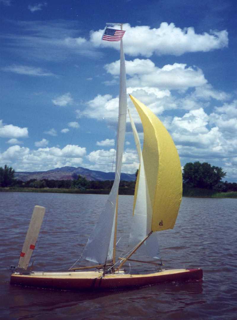
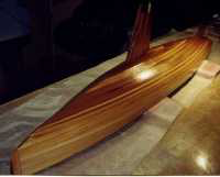
Hull 2: Hung together and didn’t leak. Planks fastened with direct application of West System Epoxy (later improved upon.) Bulb fastened in steel-reinforced fin (satisfactory). Hull weight about 3 1/2 lbs (including fin, excluding lead bulb). A real hodgepodge of patches and reinforcements, best described as a blob of epoxy with wood running through it, but it gave me hope. Rigged and sailed in the free sailing Regatta held in August 1999 at San Francisco. Came in 8th out of 10, so it wasn’t all bad. This is the boat shown above. Scrapped.


Hull 3: Better version of Hull 2. Midway through I started experimenting with tacking planks with CA glue and bonding them with epoxy later (a success, described in more detail below). About 3 lb, owing to fewer patches; still nothing to show your friends. Sawn apart to check bonding (just fine); parts trashed.
Hull 4: Almost right, but botched the tapering of the planks. Went back to the library and found out what I was doing wrong. 2 lbs 12 ounces, owing to tighter seams and even less epoxy. Stress tested to destruction; cracked at about a 210 lb vertical compression load. (Test method: I put it upside down on the floor and stood on it while holding stuff.) Confirmed faith in construction method. Scrapped.
Hull 5: The one documented here. Came out at 2 lb 6 oz. The steel-reinforced fin weighs a little under 8 oz, so the canoe body itself is a hair under 2 lb, with two coats of West System epoxy on the inside as bond/sealer and one coat on the outside as sealer. This is at or below what can be achieved with fiberglass. Was to be rigged as a convertible free sail/radio boat and sailed in the 2000 Regattas at San Francisco (free sail) and Marblehead (free sail and radio events). Decided it wasn’t up to it, so I gave it away to a beginning skipper who turned it into a neat “fun” boat.
Hull 6: The one sailed in San Francisco and Marblehead in 2000, construction documented in the next section. Sold off to another Vintage M enthusiast.
Hull 7: The first real “keeper,” documented in the third installment. Sailed at San Francisco in 2001 and taken to England, where she sailed at Round Pound in Kensington Gardens and Fleetwood.
Construction
Rip Tide poses several construction problems. She displaces about 18 lb, with 14 or so of that in the bulb. This is a lot of weight at the end of the fin, and especially in a free-sail model, which runs into rocks and pond sides all the time. When she collides with something solid, the hull stops but that 14-lb bullet doesn’t. So everything has to be tied together pretty well. The hull form is very tricky to plank; if you study the section drawing, you’ll see that a plank along the waterline has to be twisted well over 45 degrees from stem to stern to conform to the design. As we’ll see, I still don’t quite have that down pat.
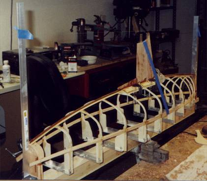
The building board is a 1.5 by 0.75-in board on a 2.5 by 0.75-in spine. The narrow form is chosen to permit getting your hands down inside to epoxy the interior.
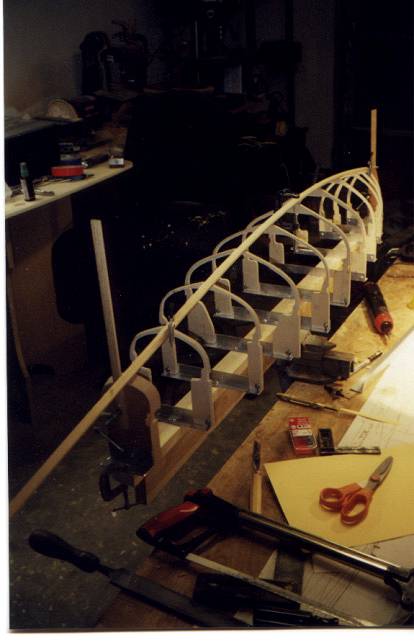
The frames are 0.25-in aircraft plywood (the model airplane stuff). I saw them to shape on a scroll saw (a small bandsaw would probably be better) and then take the taper off the top view of the hull. I set the tilt table on my bench sander to this angle and sand the taper in. Then I saw out the inside, leaving 0.25-in square frames. They are then bolted to a 0.75-in aluminum angle, which makes alignment simple.
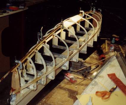
I work this way in preference to steamed (bent) frames for several reasons. One is speed of construction; with a little more effort than it takes to make the shadows (formers) for a steamed frame hull, I have all my frames done. The arrangement is also handier because I can clamp stuff to the frames as shown in the picture. I also think it’s stronger.
The keel is built up, eliminating the need to carve the “rabbet” or inset for the planks. As shown here, a spruce longitudinal is epoxied to the frames. It will then be planed to the angle of the sections, and a teak part (for bump resistance) added later. This technique worked well except at the bow, which I should have foreseen.
The bow and stern blocks are 0.75 in light mahogany. Having thick blocks at the ends for ample glue surface was a lesson learned.
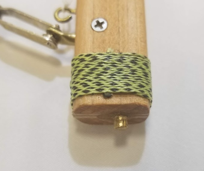
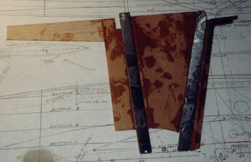
The fin is laminated from three layers of mahogany epoxied together; the center is 1/16 in, and the outer ones are 3/32 in. The core consists of a teak leading edge, a mahogany center, and two strips of 1/16 by 1/2-in stainless steel. This makes for a very strong fin. Hull #2 has taken some pretty phenomenal shots without the hint of a crack or other damage. The bulb is held on in a non-obvious way, evidently pioneered by Bob Sterne. The bulb is split horizontally instead of vertically. The top half is slotted to accept the stainless strips. The hole in the bottom of one of them is for a 1/8-in stainless pin that goes in a channel in the bulb. After the top half is aligned and “potted” in place, the bottom half is epoxied on with a sheet metal screw for safety. Believe me, once you do this, that bulb is on there for good. [Aug 2001: Although as I learned at San Francisco, that doesn’t mean the fin is necessarily there for good.]
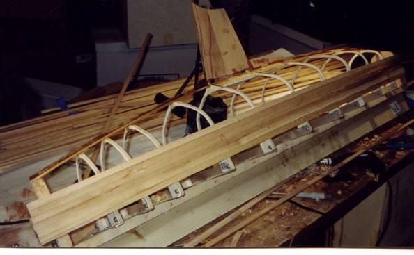
I plank using Al Hubbard’s technique of going down from sheer to garboard instead of the other way. The planks are horizontal, parallel to the waterlines, and not tapered except to correct unevenness. I got this idea from C.R. Griffin’s book Model Racing Yacht Construction, sadly out of print.
The planking process is as follows:
I plank sitting down with the hull in my lap; this way I am looking down at the seams and can see when I have gotten them tight. I use the thick, slow setting CA glue and the liquid accelerant or “activator.” I’ve had the best luck with the “Great Planes” brand used by the R/C fliers. I put a drop of CA on the end block, position the plank tight against its neighbor, and “poof” it with a spray of accelerant. It will set up almost instantly. I then work my way along the hull frame by frame this way. If a plank has warped, making a gap in the seam, I may rub a little into the gap, squeeze the planks together, and “poof” it. This goes quickly; the course of planks you see is about 4 h of work (both sides). Do this with plenty of ventilation. The fumes from this stuff are not good for you.
You may wonder why I don’t just use CA and leave it at that. Three reasons: CA doesn’t last, CA doesn’t like moisture, and CA doesn’t like shocks.
Compared to planking with permanent adhesives, this is a pretty forgiving process. If you don’t like the seam, just cut the plank off, taper or bevel or whatever, and glue it back on. One thing that is important to do is to remove all the little glue beads that might build up on the frames before you put on the next plank.
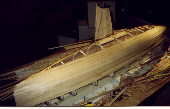
Second course of planks, doing the curve of the bilge. The arc of the planks (looking down from above) is too great for the 1/2″ planks so they are cut down to a little over 3/8″. Note that we are now planking from keel to keel instead of end block to end block. This, and the curve, involves tapering the ends and bevelling the edges of the planks. I prefer to use a wood plane for this rather than abrasives; our Winter 1999/2000 newsletter will have an article on planes in it.
After this course, the interior of the hull is given two coats of epoxy. The first coat is mixed with a small amount of sawdust to form a runny filler; this is pressed into any interior seams that are wider than necessary owing to overenthusiastic beveling. Wear latex gloves when working with epoxy. Seriously. Besides being the very dickens to get off your skin, repeated exposure to epoxy on your skin can trigger epoxy allergy. This means you break out in a rash when you even get close to resin; in serious cases, your whole body breaks out. End of hobby.
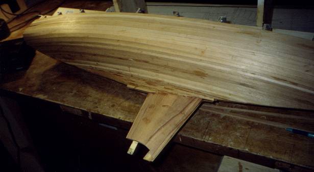
As with tapering and beveling planks, I have the best luck in fairing by using a plane; in this case a 6-in block plane. The big danger in using a plane is getting a flat surface; this can be avoided by watching the width of the shavings. It really makes you feel like a boat builder to peel off 0.002-in of wood in one silky smooth pass. One word of warning: clean up often, those shavings are incendiary.
How to get a nice sheer: Clamp a batten in the middle at the point of minimum freeboard. Bend the batten into a smooth curve to one end and clamp, putting intermediate clamps in as necessary to adjust the curve. Ditto the other end. Sight from the side at a distance and both ends to make sure the curve is smooth. Use the height guage (you can make a simple one out of wood — I saw this old beauty in an antique mall and couldn’t resist) to get the second batten parallel to the first. Then draw the sheer line and cut the frames and planks to it.
And Now Presenting … Hull 6
Well, after thinking about it for a long while, I decided Hull 5 had too many errors even for me, so I constructed Hull 6 which turned out to be a keeper. [Aug 2001: Well, not really, but it was an improvement. The new owner of Hull 5 painted it and turned it into a perfectly adequate radio boat. The bow, besides being the wrong shape (too much “rocker,” or upward curve) was way too weak to take the shocks a free sailing boat must endure.]