
- Title. Author. Summary

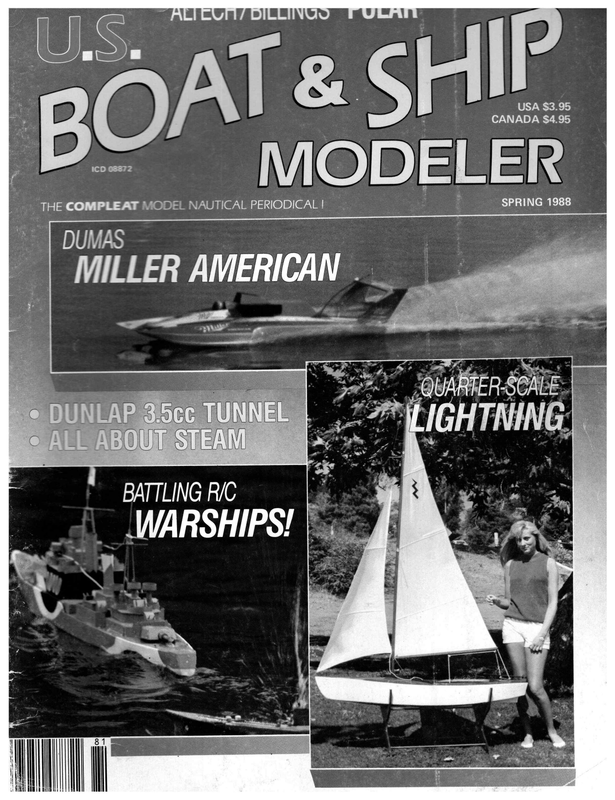
USA $3.95 CANADA $4.95 ‘THE COMPLEAT MODEL NAUTICAL PERIODICAL! DUMAS . MILLER AMERICAN . BATTLING R/C _ WARSHIPS! WE =——— RD ee tag = eo oe so =o ers of the deck beams for strength. Preparatory to installing the radio board and winch, decide on the location and size of your hatch. The dimensions shown on Figure 2 are minimal, don’t make it smaller. Conversely, the bigger it gets. the more water can get in, especially & the edge goes under when the oat heels. Draw in the hull the borders of the hatch. The forward end of the ra- . oo boerd and the after end of the winch meec t be located directly under the Opening so that we can remove them. Por 12 US 55 we will have a much larger than average hatch and will site all the gear where it is very easy to get at. Photo + shows the deck cutout to receive the hatch. A 1/16 plywood colleris placed under the deck, protruding about 1 4 inch into the opening (Photo 5) prowidimeg a lip for the cockpit to rest om. While sailing, the edges of the hatch wil be sealed with white tape, simple, light and very watertight. The cockpit is vecuum-formed ABS plastic and is very lightweight and doesn’t require painting. Figure 6 shows an exploded view of _—_ JB SWIVEL MOUNT oa mae 2 generic radio board. The board is made of 1/8 or 3/32 plywood with its Size determined by the servos to be *§ TO MIDSHIPS DECK BEAM ee MAXIMUM B/8″ GROWN 28 MEASUREMENTS MADE FROM BOW \ step block approximately 25-1/2 inches aft of the bow (see Photo 3). A round strut, well sanded, will eliminate snagging of the jib sheet while sailing. Also waterproof the strut with a coat or hwo of resin. These boats last long enough that one needs to be concerned about the bottom of the strut getting dy ret after 10 or 15 years! Notice the gussets which have been worked into the corn- They work and are simple. Complexity on board your boat will work fine up until you are six inches from winning a race, and then they’ll go bad. Murphy himself rides on each of our boats! Cut the mast compression strut to length and fix it underneath the mast NOTE: po* BASELINE used. It is then attached to athwartships MAIN SHEET DOT 44 1/2″ j FIGURE 2 — DECK FRAMING, HATCH, SHEER AND J8 SWIVEL DETAILS 20 ahaa | Struts (by a slot ait and with screws forward). Pit the struts to the slope of the sides of the hull, allowing room for oneinch square beds of 1/8 plywood, mounted with thickened resin to act as lands for the struts. In our case, we have enough elbow room to treat both ends like that on the left of Figure 6. In addition, we can use one board to mount everything on, thus simplifying the installation. The rudder servo needs to be on the centerline or near to it. The jib trim servo should be on the side where the jib sheet will wind up. In our boat, the proportional sail control unit will plug directly into the radio, so we don’t need to provide a separate winch switching servo. If you will use a simple double- U.S. BOAT & SHIP MODELER
FIGURE 5 — RECOMMENDED BALLAST CONFIGURATION MEASUREMENTS TAKEN FROM MAXIMUM LWL EXTREMITIES INITIAL POUR = 14.5 Ibs pole double-throw switch to run your sail control unit in either direction (called the bang-bang arrangement), mount the R/C servo that runs the switch on the other side. In addition, the following need to be arranged for access through the hatch: rudder pushrod dis- connect, on-off switch for radio, anten- na disconnect, frequency change on receiver, and connector for R/C battery pack. The receiver can be mounted under the board, but I generally put it up on the side of the hull using a bit of Velcro. The slack in wiring allows me to pull it up to the hatch opening when I have to change frequencies. Put a banana plug or similar connector in the antenna wire so that the receiver can be removed from the boat while the antenna stays behind. Mount the sail control unit on or underneath an 1/8-inch plywood piece. You would like to have the winch arm as long as possible and that means somewhat near the upper part of the hull. But youne_. toalso consider mounting the sail control unit as low as possible to reduce its heeling moment. As you can see, there is a compromise to be reached. Contrive to make the mount- cisely what is required for careful trimming of the sails on the weather legs of the course. A “bang-bang”’ SCU is connected to the SCU servo switch with a four-wire cable. You may wish to use some sort of unplugable connector so that the SCU can be separated from the R/C board. Similarly, the SCU is connected to its own battery pack. A pack of six AA NiCd batteries seems to be a workable Jib Sheet to Jib compromise between speed of winch rotation and the ability to trim the sails in small increments. Suit yourself. Use a two-prong, polarized connector with the male connector attached to the battery. The routing of the mainsheet is shown in Photo 8. The main sheet is attached to a cleat on the centerline of the boat about four inches from the stern. Continued on page 50 Sheet exit guide deck in Club Block /screweye, Jib sheet fairlead ing free of any protrusions that would be able to snag a sheet. Locate the winch just aft of the mast compression strut. Be sure that the rotation of the winch arm does not interfere with the mast compression strut. Figure 7 provides a plan view of a generic installation. The deck beams have been omitted for clarity. For best results, the sail control unit (SCU) arm needs to rotate through an angle of about 150 to 160 degrees. When close hauled (with the sails sheeted in to beat to windward) the SCU arm should be almost parallel to the centerline of the boat. This provides for a very small amount of sheet to be pulled in for each degree of winch rotation. The result is a very strong pull on the sheet with very small amounts of sheet being pulled into the boat; preSPRING 1988 Sail Control Unit Rudder Servo Jib Trim Servo Block /screweye, mainsheet fairlead Sail control unit servo Radio receiver Rudder /tiller arm Mainsheet cleated off for adjustment Radio antenna —) Mainsheet to main boom | | | FIGURE 7 — R/C AND SAIL CONTROL GEAR INSTALLATION 21
By CHRIS CLARK… For the scratch builder who prefers one-off wood construction to fiberglass molding, here’s a way to go. hoto 1 shows my original design 52-inch R/C sailboat, ‘‘Blade,’ built from materials available from _ through the boards at your loc= and pick those that have & are relatively dry, and area most building supply outlets. Construc- _ if possible. tion of the canoe hull with its compound PLANKING surfaces demanded either carving from Set your radial arm or table foam and fiberglassing, or use of the the cedar boards into 3/16 more traditional plank-on-frame tech- _ strips. You will probabl nique. I chose the latter method and _ three or four boards ffacte produced a hull which, after careful number of good quality strips = of finishing and painting, gave the appearareasonably large model. There = ance of a factory-molded glass hull. € as you cut through the the strip breaks, but the cheap enough that wastage de a problem. The-cut strips h on both edges as fence ough-sawn faces. Set up ble to joint the edges of the traight router bit (preferie) and a couple of layers of pe on the outfeed side of the uter table fence. If you don’t have a Assuming that you have an accurate full-scale Lines Drawing of the boat which shows the full profile and all frames or body sections, and that you have access to the use of a jig or band saw, radial arm or table saw, and preferably a router table, production of the materials necessary to build the hull and construction itself is a relatively simple matter. Basically, the profile and frames are cut from plywood, the frames glued to the profile, and the resultant skeleton planked with cedar strips. MATERIALS I use 3/16-inch birch plywood for the profile and frames. This plywood is obtainable as 2 x 4-foot “‘Handi-Panels”’ for home do-it-yourselfers and is of good quality both sides with few core voids. Common 1-inch x 6-inch x 5-foot cedar boards used for fencing are ripped to produce the planking strips. Sort 30 The author’s original design 52-inch long R/C sailing yacht ““Blade.”’ Hull was built using the method described in this article. Framework shown in lead photo, above. U.S. BOAT & SHIP MODELER
SN ; Ss NY — rame tA Stations | SPRING 1988 j \n , — N Io Posts Sad i CUT OUT I A CUT OUT Planking a router table, a few passes with a sharp hand plane should clean the edges reasonably well. Once jointed, you should have beautiful clear-grained strips approximately 3/16 x 5/8 inches up to 5 feet in length. HULL CONSTRUCTION Transfer the complete hull profile from the full-scale drawing onto the 3/16-inch plywood, using a dressmaker’s toothed tracing wheel. Mark the position of each frame (frame stations) along the length of the profile. Similarly transfer and cut out all frames. I cut the full frames at this stage making allowance only for the thickness of the planking strips. Next, cut each frame in half exactly at the vertical centerline and remove enough material on either side of the cut to allow for the thickness of the profile, as each frame half will be glued to the profile at the frame stations. Next, cut out as much plywood as possible from the profile between each frame station leaving “‘posts’’ on which to glue the frame halves. Do the same for each frame half. The resulting effort so far is shown in the sketch. I usually leave about 3/8 of plywood around the cutouts, as a lot of this structure will be cut away and discarded after planking in order to open up the interior of the hull for installation of radios and other hardware. You can now glue the frame halves to each side of the profile posts at their respective frame stations. Take care to ensure that the frames glue up at 90 degrees to the profile. I use a white glue such as ‘‘Weldbond”’ for all my construction. It sets fast, is extremely strong, and provided joints are sealed from moisture, is perfectly acceptable for boat building. PLANKING Once all frame halves are glued to the profile, you will have a wobbly structure ready for planking. Screw or clamp the mwa —, Vi in \ “ Frame half gluedto profile Section upside-down skeleton to blocks attached to a particle board construction base, ensuring that the profile is straight and true. Plank the hull with the cedar strips in the usual manner, working alternately on either side of the hull to minimize induced stresses and possible hull warpage. You will need a variety of clamping devices including small spring and C clamps, map tacks, and elastic bands. Don’t use permanently installed nails or brads, as these cause all kinds of trouble when finish- ing the hull. Once planking is complet ed, the hull will be extremely rigid and can be released from the construction jig. Once you’ve laid out all hatch locations, most of the interior plywood frame and profile structure can be cut away using a sharp X-acto saw, and rough ends ground away using a ball mill in a Dremel tool. I usually leave the structure intact for a few inches in the bow and stern of the boat and at the mast step location. The deck can be planked in the same manner as the hull, or you may want to use the more expen- sive 1.5mm baltic birch plywood avail- A-A able at most good model shops. In either case, remember to install adequate backing plates at fitting attachment points before decking the model. Photo 2 shows my current project, a 60-inch sloop, at this stage of construction. HULL FINISHING Once planked, use a very sharp block plane and spoke shave to start fairing out the hull. Follow with 80- and 120-grit sandpaper and use lightweight auto body filler (microballoons) and auto body spot putty to eliminate bumps and hollows. Care at this stage in preparing the hull for sealing and painting will pay big dividends in the appearance of the finished model. I seal the wood with two coats of polyester resin, thoroughly sanding the exterior of the hull between coats. Follow with a primer and at least four or five coats of a good-quality high-gloss auto enamel wet-sanded progressively from 220- to 600-grit between coats. Take your time and you’ll finally have a model which the weekend sailing crowd will swear is fiberglass! ° 31
MADE INUSA of the system after the rig is up. The sheet runs forward to a fairlead, then aft to the sail winch arm, and finally forward to the sheet exit guide and the jib club. Use a fishing snap here too for a consistent setup from day to day. I ©1985 CARL GOLDBERG MODELS, ING Squeeze ’em! recommend 30-pound test line for sheets so that they break rather than a boom, mast, or winch arm. (Note: If you are squeamish like I am, I would check the operation of the SCU and make ad- justments before I put the deck down. So prepare the following, but don’t put the deck down until the rig is done.) The first step in deck attachment is SUPER to mark the location of the sheet exit guides on the underside of the centerline of the deck by laying the deck on the boat and marking from inside with a pencil. Then drill the deck 3/16 inch *© (ETT WT. 202. (56.76) to accept the sheet exit guides. If necessary, thin the underside of the mount- _ The Pros are tough, but the bottles are softies. From the half-ounce mini to the two-ounce maxi, all of the Professional Grade JetTM CAs come in the kind of squeezable, clog-resistant, bottles SSS sis es you’ve always liked best CARL GOLDBERG MODELS INC. Try them. They make it a lot easier to use a little of our best. 4732 WEST CHICAGO AVE., CHICAGO, IL 60651 into the hull and runs forward through a fairlead, which is a screw eye that has been soldered shut and carefully smoothed, mounted in a block which is Continued from page 49 mast, spankermas I mast, and pushermast. 7 parently preferred an system that probably much sense. . . Monday, Tuesday, Wed nesday, etc.! Anyway, naming the seven masts nautically o question for the 64-1 pot! Also, it was the only seven-masted schooner in the world. a Strictly Sail… Continued from page 27 When the boat is all sealed up, you will be able to adjust the close-hauled position of the mainsail by bringing the sails in with the radio, and adjusting the main boom from here. The sheet goes strongly fastened to the hull. The mainsheet runs forward to the sail winch arm, then aft to the sheet exit guide and up t the main boom. Use a fishing snap t attach to the boom fitting. That way you each will make the same attachment time and a reproducible setup of sheet is a bit more complicatcause the class rules allow the jib “s proven hull holder and is has a been cispley as well. iid and features: ik ge! 40×11 coat deck $7 moe : yellow treked S – transom -compiete basic kit 40/60 size $5 3422 50 3rd Ave W Hibbing Minnesota SS746 shipping hull installed tion installed structions Ss zs 134 = ing blocks in the area of the sheet exit guides so that the sheet touches only the guides while entering and exiting the hull. Check the class rules for allowable deck beam dimensions, and, using masking tape, strap the beam to the proper contour. A 1/4-inch plywood pattern is a good idea for plotting the largest beam allowed and making the hull fit inside it. For later reference, mark the location of the chainplate backup blocks on the outside of the hull. I usually make some cardboard patterns so that I-can draw them on the deck after it is down and I am locating the chainplates. I drill a small hole at the location of the jib mounting bolt in the deck so that I can use a piece of stiff wire to locate that point accurately as I lay the deck down. Use plenty of thickened resin to bed the deck onto the beams and hull lip. Use only a little catalyst so that you’ll have plenty of time to get everything just right. Tape heavily all along the deck edge and that should pull the deck tightly down against the deck beams. Don’t get overeager and ruin your beautiful work by untaping the hull too soon. Let it cure completely. When fully cured, remove the tape, including that which you used to hold the deck beam measurement. Finishing the deck/hull joint is a matter of personal preference. Figure 8 indicates some successful approaches. The important thing is to have a com- plete seal at this joint. The joint goes underwater routinely while sailing and needs to be tight. While waiting for the next installment, you should prepare either a 72-inch wooden mast or purchase a Continued on page 56 U.S. BOAT & SHIP MODELER
QUARTER-SCALE LIGHTNING Length – 57’ Beam – 19.5” Mast height – 80” Sail Area – 1593 sq. in. Overall Height (c/b to masthead) 101” Displacement – 23 Ibs. Quarter-Scale LIGHTNING By CRAIG LaCHANCE… The “Lightning One Design’’ has been a popular racing sailboat for 50 years. “Shrink to Fit’ is the author’s quarter-scale R/C version of this classic. SPRING 1988 here are numerous ways to ob- ; tain plans or drawings for a scale boat project. Your local library will have books available on sailing or small craft that will often include the hull lines, which once understood (see USB&SM Summer ’87) are enough to start you on your way. An excellent and often free source is boat manufacturer’s promotional brochures, which usually also show colors, rigging, and sail outlines. Send for them from their ads in boat magazines. Small display-only model kits provide plans and parts templates that can be scaled up and detail added to the now more-workable size, and then the unbuilt kit sold to recoup most of its cost. Or, plans for the full-size boat can be purchased, oftentimes at surprisingly little cost, that will allow you to replicate in miniature not only the final form but also the building exsperience of the full-scale boat: 51
ly not factors we need be concerned with; we have the luxury of choosing wood on the basis of economy and aesthetics alone, with workability a minor consideration. This five-foot boat, which is about as big as can still be considered practical, was built with two sheets of 3/32 mahogany ply, normally used for sheathing hollow-core doors. Available at most building/hardware stores for about $6 each, they come in three by seven-foot sheets. Also used were some scrap pieces of redwood and pine, the redwood adding a nice contrast in color and grain. Epoxy resin was used exclusively as an adhesive. Since there are almost no straight lines on a boat, cabinetry-like woodworking machines are unnecessary. A a. saber or jigsaw and small belt sander will suffice for almost everything for a project of this magnitude, with some small amount of ripping on a table saw. Don’t have one? Neither do I; make do with your skill-saw mounted inverted in an old chest of drawers, with the blade coming through the top. For some there is much satisfaction to be had from the solving of all the little problems that surface in a scratchbuilt project. In this instance, much consideration had to be given to correct construction sequencing, at least in the beginning stages. Some assembly technigues were unorthodox but proved “‘Shrink-to-fit’” was built from the plans (six sheets) for the full-size boat, obtained from the Lightning Class Association for $5. This is their “‘unnumbered”’ set, meaning a boat built from these plans can’t be registered and thus can’t be raced in a sanctioned Lightning Class race. The same plans including a registration number are $70. Most plan vendors now offer abbreviated “study”’ plans for $7 to $10 that are sufficient to build a model from, or there are even many full-size plan sets available for under $50. It is almost certain that once the plans or drawings are obtained, some scaling of them will be necessary to arrive at the size of the model you want. Photocopy enlargement works well if you’re not going more than half-again as large; it gets complicated or expensive after that. An indispensable tool for enlarging (or reducing) to virtually any ratio of scale is a pantograph. Available commercially, they can also be made quickly and cheaply. One of the nice things about scale boat building is that the wood selection is non-critical. Weight per volume, tensile strength, compressibility, are real- workable. With the deck cut slightly oversize, the built-up frames were glued to its underside, giving the deck its gunwale-to-gunwale camber. Then the centerboard trunk (with finish applied inside and out) was mounted to the appropriate frames. The keel was then added, along with the stem and transom, springing the deck along its length to give it the sheer curve. After everything was waterproofed inside, the plywood hull sides were added, then sheathed in fiberglass. The temporary connectors between sides of the frames in the cockpit area could then be cut away, detail R/C gear moved out from under the decking for photographs. Rudder controlled by two paralleled servos. Key disconnects used for rudder cable hookup. Weight on servo board are for trimming boat waterline. No R/C on sail control, as boat is only used for sport sailing. 52 U.S. BOAT & SHIP MODELER
Pictures above and right show how rudder moves tiller and ““Vern’s” arm for neutral and left turns, then disengages from tiller for right turns beyond “Vern’s normal reach. added, and everything inside waterproofed that hadn’t been done previously. Spars were built-up of pine encased in plywood, then a slot cut in for the sail, with a wider slot at junction of mast and boom for admittance of the bolt rope. Cable rigging is plastic-encased stainless fishing leader, 60 pound test. Spreader and vee strut are steel rod with aluminum covers. All of the rigging bracketry (tangs, tongue, and mast top plates) was made from roofing rain gutter sheet metal, the blocks (pulleys) from hardware store stock, cut, ground down, and drilled. Cam cleat jaws are shaped from plastic, while the main sheet cleat was filed from some scrap flat stock. The radio was mounted to the underside of the deck with the receiver, switch, and batteries forward, ahead of the mast, on a slide-out tray. Two servos in tandem on another tray in the stern drive the rudder by cable. The antenna runs the underside of the deck alongside the cockpit area, and allows (sur- ae Three centerboards (I to r): for static display, for normal wind and water conditions, and for heavier seas and wind. SPRING 1988 Molds for lead weights attached to normal-weather centerboard and faired in with auto body putty. 53
prisingly) about 200 feet of range with the transmitter antenna collapsed. Sails were made from 3/4-ounce ripstop nylon (available at many fabric shops) by my wife, who is now quite sure of keeping all of her six cats, forever. The library provided books on full-size sailmaking; a local fishing tackle shop was the source of the small splitrings on the jib-stay. The scale-size centerboard (made from the aluminum of a discarded road sign) was ballasted with two five-pound lead fishing weights. Although the boat sailed well with this, the less-than-scale appearance was a detriment. After cut- ting another centerboard, pine blocks were epoxied on each side and then shaped on the sander. A plaster cast was made of each side, then lead poured into each mold. The wood was then chipped off and the lead castings bolted on, then faired in with auto body putty. Although this centerboard is much more pleasing to the eye, the bulb board is still kept for use in heavier weather, as its extra couple of pounds adds needed stiffness during those conditions. One of the more interesting challenges was in getting ‘“Vern’’ to appear to move the tiller while staying seated, and still have full rudder control to both sides. Knowutimean? Vernis a vinyl figure whose head and limbs were repositioned from his original pilotfigure posture. Most of his left arm was replaced with string, with cotton used PLANS INFORMATION — Contact the International Lightning Class Association, 808 High St, Worthington, OH 43085, for information on ordering complete dimension Tr PART ya plans, and see page 78 of this issue for > t_d|f:«S« eee se | Ordering full-size quarter-scale pat- || Pas. (oPrional) tem drawing, No. US1882, — =)(arriowas LATE BACKING PIECES 4 __ J 3 22k A o{‘oesiew ral 7 \. MAINSHEET CLEAT ke SMAINSHEET BLOCK feist nel AT LEAT OfDRUM ° (OPTIONAL) Ss —— =e ») as ° OrriowaL AS TO TYPE AND LocaTiON NOTE: CENTERBOARD PENNANT 8LOCKS OL Ae none TRANSOM ~ See Owe. NP 265) 2 NOTE! FLOOR FRAMES FORWARD OF SIDE FRAMES — eg ee OF TRUNK y | E | Aa i! wer T | ae SEE DNG.NO.268-/0 | 3 — — TRAST STER ene” an) rn | YO “ PIECE OF BRASS may BE EXTENDED DOWN THE TRANSOM Rm OFACE 169″Pitt. PANG. em AT OF TH SKEG. ITA TRACK 1S USED SAE MAY BE SET ON A BATTEN PROVIDED BATTEN DOES MOT EXTEND BELOW NORMAL POSITION of THE RUDDERORTHE A ETHE FRS. – 1 . RECOMMENDED Kune rye WOOD To BE AS SHOWN, OR EQUA 4 HEGL -1%’s6″ RAH. i. LOT-%e” WIDE | | AL. AN. ~ We Pitts Ae, igs TRUNK LO6S-(%’9″ PHAM, bi Peogas.» spgugg ncaa essa 2 TRUNK -%° £8 TRUNK SEAT FRANING ; RORMAL DISTANCE Erwan Ht ron we SEAT SLATS B MAK \ WATER LINE & DOES NOT CHANGE THE SPO rea ROPERS DECK B. \ |] SRACES. Gal” seRUCE FL00R a ow. ee _ : CANVAS = Cy 10%, 1D. BY” La THICK, FU MA. et QAMAN te’Tomen morveul ERArTES gett i _ – Lie | TM _ t : Y) 2 6 \ | x | egos + | 4 lg 4 ay —— .! 9 i DESIGN No. 265 = L/GHTNMNG =~ 137″ ny ONE DESIGN CLASS 3 SCALE: 1-0″ ; jan a [LMLD.STATIONS _Jo_ } —L / / a.) i 7 fas _ {7 % Hi a CHE Loew crwt xen | Derren Anan wont |3 a eres, _ i ! \ SOE FLANKING, y DOWN. COVERE| sve “=. Sages||__ 80x. sioco Te 0° SPACER BETWEEN jee ee DECK OK warerPRoor SUC St venco| CEDAR, COCKPIT COAMING VP DESIRED TO STIFFEN THE SKEG AMS‘a Nove: |z J Nore: erat EDGE OF THE RUDCER le a pieces. DED PER PLAN 50 4 yd SPARKMAN & STEPHENS, INC weasr 4478 ee 1 ST WY 04 GIOAR SF My – 01.192 54 U.S. BOAT & SHIP MODELER
‘inside his shirt sleeve to provide form. From center to full left rudder, the tiller moves his arm most realistically. When the rudder is moved to the right, the tiller and top of rudder disengages from the rest of the rudder, straightening his arm but not moving it much past center. A length of piano wire in a groove on the underside of the tiller springs the tiller back into engagement with the rudder whenever the rudder is returned to neutral. That the spring pressure needed to be overcome during right rudder control is the reason the power of a second servo was necessary. Otherwise, one would have been sufficient for the rudder, even on a model of this size. In order not to compromise scale appearance, it was necessary to forego adjustable sail positions. The sheets are adjusted for a close reach before launching; the only. point of sailing this seems to noticeably affect is when running (downwind), and then only in relation to other boats that can sheet out. Otherwise, her grace and speed on all other points are a delight and a surprise to most who observe her. e Rigging details follow that of the full size Lightning very closely. Why change something that has been so well proven over so many years of development and use? SPRING 1988 55
HAYES WHIP ANTENNA 28 OCTURA X-SERIES PROPELLERS Vertical whip antenna replaces any 18 or 36-inch receiver antenna for R/C cars and 4NEW SIZES boats. Connec tors, vertical and horizontal mounts and safety ball all included. model boats, there are 24 Octura competition proven “X” series metal propellers available. Rang- whip only 1/32 diameter for minimum wind resistance. Available at your From direct drive electric R/C boats to 30cc gas powered R/C Stainless spring steel ing from the X427 up to the X482 there is an Octura “X” series pro- local dealer. peller for any engine class and boat class legal under IMPBA and NAMBA rules. Last two numbers indicate propeller diameter in millimeters > while the pitch is 1.4 times the diameter. The only satisfactory replacement for an Octura propeller is an Octura prepelier. RECOMMENDED APPLICATIONS X427 ) Direct Drive X432 > ElectricX435 ) % Dia. Shatt X430 X430RH X437/3 3.5 Outboard ) X440 and Inboard 7.5 Outboard and Inboard | X440/3 X442 X445 X447 {xs X450/3 X452 X452/3 Ms .lcc Outboard ( X455 sme Maer 65 Hyaro Scale x460 | X460/3) X462 90 90 HAYES PRODUCTS 2610 Croddy Way, Unit A Santa Ana, CA 92704 Continued from page 50 72-inch aluminum extrusion from one of the many sources of supply. Make jib club and main boom 21 inches and 24 inches respectively, and gather six single-ended turnbuckles and rigging wire that you plan to use. Send in your $20 annual dues to the American Model Yachting Association, Membership Secretary, Pat Hein, 1884 Campus Court, Rochester Hills, Michigan 48063. The AMYA Newsletter is full of suppliers advertising the bits and pieces used on today’s racing yachts. And send your questions and comments to the author, Rod Carr, 3011177th Ave. NE, Redmond, Washington 98052. Waterlines… “/ 3°” Indicates 3-Bladed Propeller * 250 Bore *X467 *X472 90 Outrigger *X482 Twin 90 Outrigger Send stamped, self-addressed envelope for price list. SUPPLIES ° shore THE R/C MODEL BOAT PROPELLER PEOPLE Octura Models, Inc. 7351 N. Hamlin Ave. ¢ Skokie, IL 60076 Continued from page 45 pening in boiler design! Boiler design must be divided into two divisions; Fire Tube Boilers and Water Tube Boilers. The latter division can be subdivided into another design, Flash Tube. Any boiler can be designed in a horizontal or a vertical configuration. Since I tend to think vertical, let’s take that direction for dissertation. As stated above, whether ‘‘teakettle,”’ firetube, or watertube, the whole idea of a boiler is to place the “‘fire’’ against as large a surface as possible having the boiler water on the other side. The most practical way to do this is to fill the boiler volume with an array of tubes. The “fire,’ which we will call flue gases, can pass up these tubes, with water filling the boiler casing, in which case this is called a Firetube Boiler. See Figure 2 for details. Obviously, for model boat propulsion, the teakettle boiler is inadequate. Firetube or Watertube? The supporters of the Firetubes and of the Watertubes are two distinct groups that are as adamant in their views as the two groups arguing the Downwind Turn in Aviation Circles. Let’s look at it with a general view. I know I will arouse the ire of both groups, but I want to advise the uninformed and most casual reader of this column of what to expect ina boiler discussion with Boiler Buffs of the Above IIk! A Watertube Boiler (WTB) will “‘steam-up’’ faster than a Firetube Boiler (FTB). A FTB will not require the closer monitoring of a WTB (assuming there is no auto feedwater makeup). The Force of Explosion Potential is greater with the FTB. A FTB will take longer to ‘‘steam-down”’ than a WTB. It is easy to see why argument is so possible; it depends on the particular application! Figures 1 and 2 are very simplified diagrams of boiler types, but similar in concept to those in model use. Stuart Turner provides a commercially available WTB that will steam an engine for a five- to eight-foot model. It is the Turner-Babcock Model 504, designed for the Stuart‘Tumer D10 TwoCylinder engines. Before we leave the boiler, we must consider the water we put in it. Of course, it must be distilled water, or we would quickly ruin our boilers with scale deposits. In addition, we must consider the amount of water in the boiler and whether feedwater makeup is required for our application. See how a simple question concerning applica- tion can get so involved? For the Really Involved, we have a “how-to” article planned (if the readers wish) for several sizes of boilers. These boilers will power a single engine in a hull, a number of exhibition engines on a bench simultaneously, or a small person-carrying launch engine. We also have some designs for manual and auto feedwater makeup pumps, if the readers so desire. Write the Editor if you want to see any of this material in Waterlines & Currents. The third subsystem is the engine. Now we have options on the options! The engine can be single-action or double-action. Single-action is like a two-cycle engine. Pressure is applied for one stroke (180-degree shaft rotaU.S. BOAT & SHIP MODELER