by John Henderson
standing rigging [R57]: The rigging that supports each mast or bowsprit on a sailing vessel and reinforces those spars against wind loads transferred from the sails. It is composed of fixed lines, wires, and rods.
Standing rigging supports the mast (R37), keeping it upright and in column while allowing some optional pre-bend in the fore-aft direction for sail shape control. Most standing rigging is wire (R66), and none of it is adjusted while sailing.
Note that virtually all of the standing rigging attaches to the mast. In the accompanying article on mast making (Henderson, John and Stoudt, John. “How to Make a Wooden Mast.” The Model Yacht. 27:1. Spring 2026. pp. 11-15.), we explained the wisdom of planning for these attachment points and pre-drilling any necessary holes while the mast blank is still in its 4-sided condition.


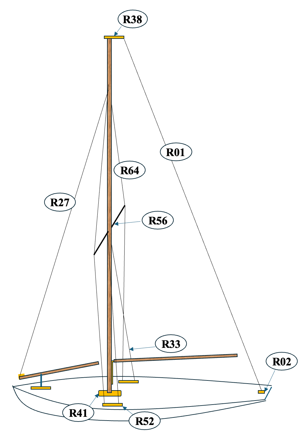
We will describe first the “big picture” and then go into the details of the actual fittings and installation.
Shrouds or Sidestays
shroud (sidestay) [R50]: Wires that support the mast from the sides and connect the mast to the deck or hull, providing lateral stability.
Arguably, the most stressed and demanding components of the standing rigging are the “shrouds” or sidestays (R50). Their tension loads and interaction with the compression load on the mast have been described in detail in a separate article (Henderson, John and Stango, Victor. “Structural Mechanics of Wooden Masts.” The Model Yacht. 27:1. Spring 2026. pp. 16-22. ).
At a minimum, there will be a pair of sidestays attached to the mast at or near its top (R64), or perhaps at or near the height of the jib stay or forestay attachment. These sidestays usually have spreaders unless the sail area is small. There is often a pair of lower shrouds (R33) that attach to the mast at the height of the spreaders.
The shrouds attach to the deck near the edge. The upper shrouds will attach close to the same fore-aft position as the mast. The lower shrouds attach aft of the upper shrouds and serve to stabilize any mast bend introduced by the backstay (R01). Note that, since the mast position on models is usually adjustable to control helm balance in different wind conditions, the attachment points at deck edge for the shrouds must be correspondingly adjustable.
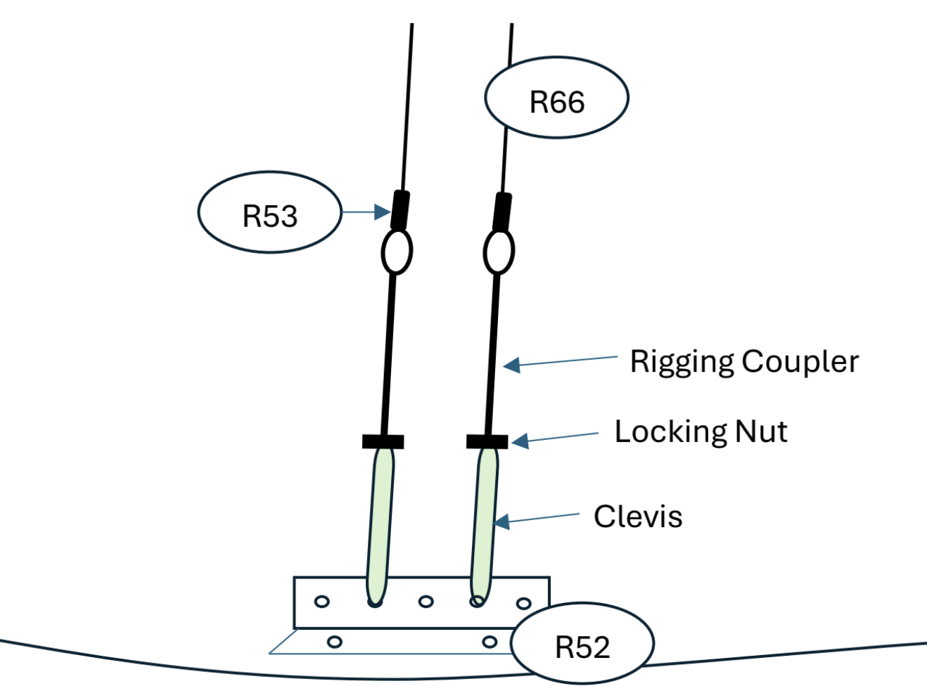
The shrouds are attached at deck level to shroud racks (R52), which have a series of holes to provide fore-aft adjustment. The shroud racks are fairly heavily loaded and must be screwed or bolted solidly to backing plates [shroud plates (R51)], which were put into place before the deck was installed and are glued to the frames, deck beams, and the sides of the hull.
The lengths of the shrouds are adjusted by turnbuckles (R63) or rigging screws, whose construction options will be covered in a separate article.
Related Articles
- Henderson, John and Stango, Victor. “Structural Mechanics of Wooden Masts.” The Model Yacht. 27:1. Spring 2026. pp. 16-22.
- Henderson, John and Stoudt, John. “How to Make a Wooden Mast.” The Model Yacht. 27:1. Spring 2026. pp. 11-15.
Mast Location
Some comments on the fore-aft location of the mast (R37) and, consequently, of the shroud racks (R52):
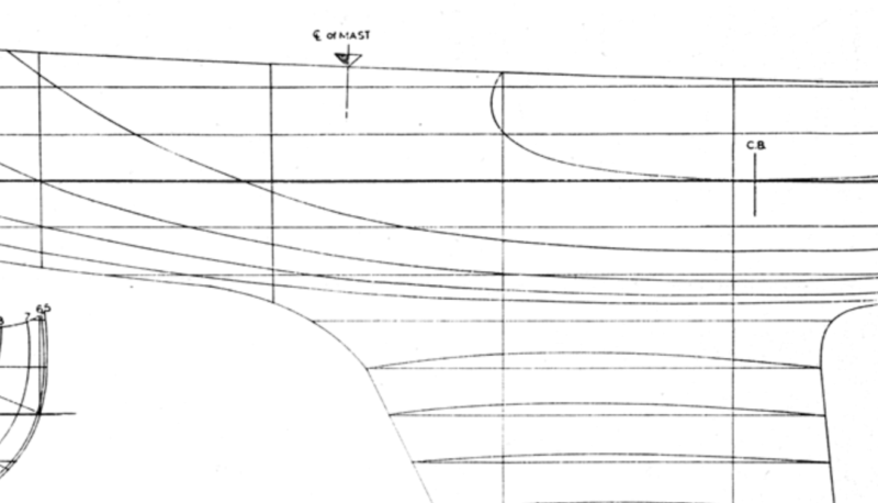
- The position of the mast is determined by the relative location of the Center of Lateral Resistance (CLR) of the hull and the Center of Effort (CE) of the sail plan. The necessary goal is to achieve a proper balance of forces on the rudder—a “balanced” helm. A description of this balance and an easy way to determine it are found in an article on the US VMYG website (Henderson, John. Helm Balance, with simple calculations of Center of Effort and Center of Lateral Resistance. The Model Yacht. 24:1. Winter/Spring 2023.).
- If you are building from plans, the sail plan and mast location are likely specified, although you should allow for a range of position adjustment around this “nominal” location. If the plans don’t show mast location (as might be the case for some lines drawings of full-size boats), you will have to determine it as described in the reference above.
- If you are restoring a model that is more or less intact, it is likely that there is evidence on the deck of the mast position. Note that this is valid ONLY if you also have the complete rig and sails. If you are re-rigging the boat using your own best estimate of the sail plan, you should check the CLR and the CE as described above.
- If you are scaling down a full-size yacht, it is likely that you will either reduce the size of the sail plan, or deepen the keel, or make the rudder bigger, or all of the above. These changes will affect the helm balance, and so the mast position may no longer be exactly as in the full-size prototype. You must re-do the helm balance calculations as above.
See the articles “Planning Your Deck Fittings.” and “Placing Your Deck Fittings.”
Related Articles
- Henderson, John. “Helm Balance, with simple calculations of Center of Effort and Center of Lateral Resistance.” The Model Yacht. 24:1. Winter/Spring 2023.
- “Placing Your Deck Fittings.” usvmyg.org. May 2026.
- “Planning Your Deck Fittings.” usvmyg.org. May 2026.
Backstay
backstay [R01]: A piece of standing rigging on a model yacht that runs from the mast to either its transom or rear quarter, counteracting the forestay and jib.
The next piece of standing rigging is the backstay (R01), and its name describes its function—to keep the mast from falling forward or breaking under pressure from the sails when going downwind.
A backstay may also be used to induce a small amount of pre-bend into the mast to control the draft shape of the sail. (This pre-bend can be limited and controlled by the lower shrouds.) The backstay attaches to the very top of the mast, usually through a mast crane (R38) that extends aft of the mast far enough that the leech of the sail will not hit the backstay when tacking. Deck attachment is to a backstay bracket (R02) usually at or near the transom.
Related Articles
- “Backstay.” usvmyg.org. June 2026.
- “Backstay Bracket.” usvmyg.org. June 2026.
Forestay and Jib Stay
forestay [R17]: A piece of standing rigging that keeps a mast from falling backwards. It runs from the top of the mast to the bow and is sometimes just called a “stay”.
jib stay [R27]: Rigging used to support the jib sail, running from near the top of the mast to the jib club to help maintain the shape and tension of the jib.
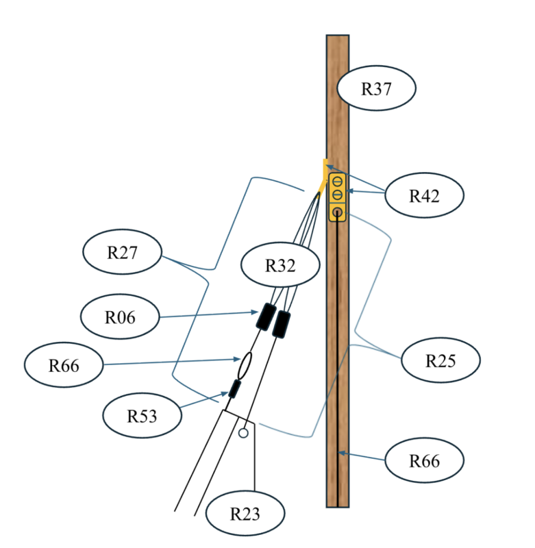
The last major piece of standing rigging is the forestay (R17) and/or jib-stay (R27). A proper separate forestay runs to the top of the mast and attaches to the deck near the bow. A jib stay is usually a wire (R66) or stiff line (R32) that runs inside a seam along the luff (R34) of the jib. It provides a firm leading edge for the jib, and adjustment of its tension can control “sag” in the jib luff. (The desired amount of sag is a design feature of the sail and may be different for different wind conditions – a topic for a separate article.)
In model boats, the forestay and jib stay functions are often combined, with the separate forestay eliminated. We note that it is often easier to rig a large model on a windy day if there is a separate forestay, even if it is only temporary during the on-shore rigging process.
Related Articles
Fittings Attached to the Mast
Mast base
Most model masts are stepped on the deck—i.e., they do not pass through the deck to be stepped on the keel. A deck-stepped arrangement is a bit weaker, but if properly done it is plenty strong for model applications, and it is simpler to provide for fore–aft adjustment. The consequences for strength are discussed in the article “Structural Mechanics of Wooden Masts”.
The easiest way to attach the base of the mast to the deck is a mast step (R41) with a simple pin in the bottom of the mast that fits into one of a series of holes in the deck. It is best to make a deck plate out of sheet brass with holes to accept the pin. See
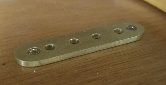
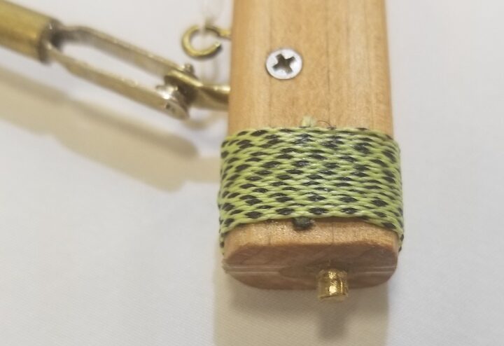
See “A Simple Mast Step on Deck” for details on making your own. Other mast attachment options may be available commercially and are listed on the Mast Step (R41) page.
See “Assembling the Mast” for step-by-step instructions on attaching your hardware to your mast.
Related Articles
- “Assembling a Jib and Main Boom.” usvmyg.org. June 2026.
- The step-by-step process for shaping and installing fittings on your main and jib booms to prepare for final assembly of the rig.
- “Assembling the Mast.” usvmyg.org. June 2026.
- Henderson, John and Stango, Victor. “Structural Mechanics of Wooden Masts.” The Model Yacht. 27:1. Spring 2026. pp. 16-22.
- “Mast Step.” usvmyg.org. June 2026.
- TMY Editorial Staff. “A Simple Mast Step on Deck.” The Model Yacht. 24:2. Summer 2023.
Masthead
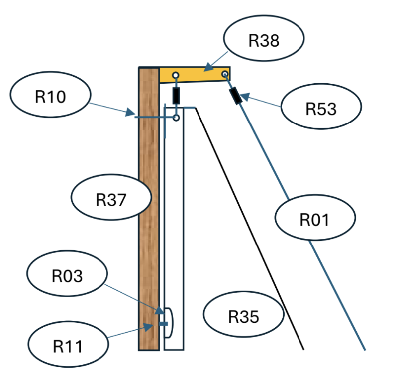
The top of the mast generally has a mast crane (R38) to which the backstay (R01) and forestay (R17; if used) are attached. The crane itself can be a piece of brass strip, approximately 1/4 in wide and 1/16 in thick or it can be made from Tee-shaped brass for added strength. The length of the crane’s extension aft is whatever is required to allow the leech (R31) of the sail to tack back and forth without hitting the backstay. The crane must be glued and pinned into the top of the mast.
See “How to Make Fittings from Tee-Shaped Brass” for details on making your own. Other mast attachment options may be available commercially and are listed on the Mast Crane (R38) page.
Related Articles
- How to Make Fittings from Tee Shaped Brass.
- “Mast Crane.” usvmyg.org. June 2026
- TMY Editorial Staff. “Tee-Shaped Brass for Various Fittings.” The Model Yacht. 24:2. Summer 2023.
Shroud Attachments
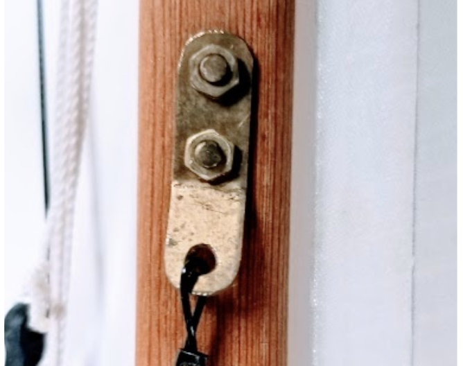
It is easiest to attach each shroud (R50) to the mast with a mast tang (R42). The tangs are light brass strips with one (sometimes two) screws or bolts into the mast and a hole for attaching the shroud’s wire loop to the tang.
The preferred locations for these tangs depend on many variables. We will provide general guidance, but there may be individual optimizations for different models. If there are specified locations in the plans or the class rules, those instructions are overriding.
The upper shrouds (R64) will attach to the mast somewhere near the top. In some cases, it might even be at the very top near the mast crane (R38). For most mid-size models, a good attachment point for the upper shrouds is at roughly the same height as the jib stay (R27) attachment point. This allows the jib stay to be tightened without bending the mast. [The part of the mast above this point can still be bent aft if desired by tightening the backstay (R01).]
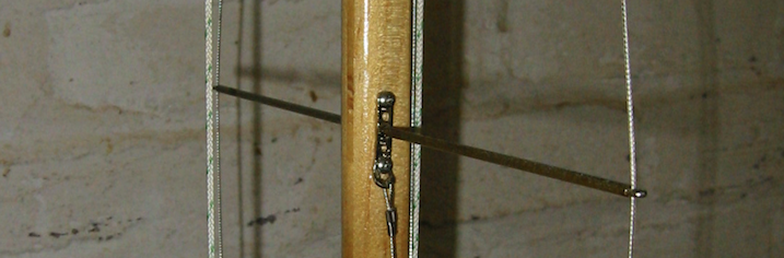
The upper shrouds usually pass through a spreader (R56). The exact location of the spreaders is usually not critical, but they work well if located approximately midway between the deck and the upper shroud attachment point. The length of the spreaders should approximately match the deck width (no wider) at the mast location, so that the part of the upper shroud below the spreaders is close to vertical. Spreaders can be made from lightweight tubes (brass is fine) that mount to a solid stiff wire or thin rod that passes through the mast. The ends of the spreader tubes are crushed flat in a vice, and a hole is drilled through which the shroud wire passes. See “Making a Spreader.”
The tangs for the lower shrouds can attach to the mast at the spreader location. It is convenient to put holes in the lower spreader tangs and pass them over the spreaders. When the tangs are attached to the mast, they reinforce the hole for the spreaders, reducing the likelihood that any spreader flex will enlarge the hole in the mast.
Related Articles
- “Mast Tang.” usvmyg.org. June 2026.
- TMY Editorial Staff. “Making a Spreader.” The Model Yacht. 23:1. Winter 2022.
Jib Stay
The height at which the jib stay (R27) attaches to the mast depends on the design and size of the jib. In some cases, the height is also restricted by class rules. If not specified by the drawings, or if you don’t have the rig for a model you are restoring, you must determine the jib stay attachment point empirically.
Making scaled drawings will work, but you can also lay the mast, booms, and sails on the floor and determine the attachment point visually. Some controlling parameters:
- The foot (R15) of the sail must clear the deck, and it is usually good to allow some space for water to flow across the deck below the sail (deck-sweeping jibs, although common in full-size boats for aerodynamic reasons, are generally problematic in models).
- The leech (R31) of the jib, and especially the jib boom, must swing freely without hitting the mast.
- If there is a jib topping lift (R62), it also must clear the mast and not foul on the spreaders.
- Most classes that do not allow bowsprits usually prohibit jibs from projecting forward of the bow.
If the forestay is a separate wire to which the jib is not attached, it can connect to the deck with any solid and reinforced screw eye (R48).
However, the jib stay (R27) must attach to the deck with provision for adjustment of the jib connection point. If the mast is adjusted fore and aft, the location of the jib’s attachment to the deck should be adjusted correspondingly, just as the shroud attachment to the chainplates is adjusted.
The jib-to-deck attachment options are further complicated by an often-preferred option to attach the jib boom to the deck at a point about 25%-30% aft of the jib tack (R59) . (Note that some classes, e.g., the Skipjack 48, prohibit this.) The advantage of this attachment point is that it serves to make the jib “self-vanging” to a great extent, meaning that the aft end of the jib boom will not lift, and the sail will hold its shape better when going downwind.
Related Articles
- “Forestay.” usvmyg.org. June 2026.
- “Jib Club Fitting.” usvmyg.org. June 2026.
- “Jib Stay.” usvmyg.org. June 2026.
Backstay
The backstay (R01) is comparatively simple. It attaches to the mast at the mast crane (R38). It attaches to the deck well aft, near or at the transom. Its length should be adjustable—a bowsie is sufficient— to keep the mast straight or to induce a small amount of bend to set sail shape.
Note that any bend induced by the backstay will be limited by the forestay/jib stay but could still create an overall bend even in the lower mast. This lower mast bend can be controlled by the lower shrouds. Setting an amount and shape of bend to suit the sail design is a complicated and interactive process.
Even with the forestay/jib stay and lower shrouds, the backstay could still potentially “overbend” the upper part of the mast. Mid-size models with adequate wooden masts generally do not have a serious overbend problem, but larger boats might. Over-bend can be limited, if necessary, with a Jenny stay strut (R22), used as shown in the photo.
Related Articles
- “Backstay.” usvmyg.org. June 2026.
- “Jenny Stay Strut.” usvmyg.org. June 2026.